This article was originally published in the September 1999 issue of
Japan's high-end tube magazine, MJ Audio Technology.
BY SATORU KOBAYASHI
This article describes a Svetlana 3CX300A1 push-pull monaural amplifier I built, using the experience gained in fashioning the 3CX300A1 single-ended stereo amplifier first described in MJ Audio Technology's September 1999 issue. This push-pull amplifier features a well-balanced voltage-driver circuit, using a differential amplifier and a cathode follower to drive a pair of 3CX300A1s with low impedance. The maximum output power is 36W at 3% harmonic distortion, using a 450V plate-supply voltage. The sound of this amplifier is very strong and dynamic, giving a larger presence in vocal sounds than my single-ended amplifier1 previously mentioned.
DESIGN GOALS
• Drive the pair of 3CX300A1s in Class A1, for a predicted maximum output of 30-40W with lower distortion than a comparable single-ended amplifier;
• Use a Plitron toroidal output transformer to yield a power bandwidth of over 100kHz;
• The amplifier will be monaural, to limit weight and chassis size;
• No negative loop feedback will be used, honoring the policy of Menno van der Veen, the designer of Plitron toroidal transformers;
• Use a power MOSFET-regulated ripple filter to save cost and weight (by replacing a filter choke);
• Obtain low ripple voltage by using a three-terminal solid-state voltage regulator for the negative grid bias of the final tubes;
• Use the Tube CAD simulator by Glassware to design the voltage driver for optimum circuit performance;
• Build the power supply circuit onto a PCB to avoid hum by providing star grounding; and
• For easy assembly and maintenance, use PTP terminal boards from Inter national Audio Group to build the en tire circuit.
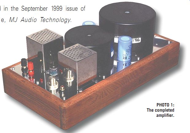
PHOTO 1: The completed amplifier.
POWER SUPPLY
I used Plitron's toroidal power transformer, model 754709. Even though this is Canadian made, it provides a 100V AC winding for use in Japan. The 340V AC-0.7A winding goes to a bridge diode to rectify, then to a power MOSFET ripple filter stabilized with three 150V zener diodes cascaded to generate 450V DC.
The resulting ripple voltage was only 14mV.
The 40V-0.1A AC winding also goes to a bridge circuit. A three-terminal voltage regulator minimizes ripple voltage to provide fixed bias grid supply for the final tubes.
A 470µF 63V electrolytic capacitor by passes the lower grid resistors of the final tubes, thus decreasing the ripple voltage to only 0.3mV. The 6.3V-6.8A AC winding drives the heaters of all vacuum tubes without any special circuitry-no DC heater power was needed.
Approximately 8V DC is available after rectifying the 6.3V AC. This drives a cooling fan to supply forced air to the final tubes. To reduce fan speed and noise, the fan runs on a lower voltage than its rated 12V.
FINAL STAGE SUPPLY VOLTAGE AND CURRENT SUPPLY
First of all, you must define the supply voltage. I determined that 450V is a good fit for the available electrolytic capacitors made by Nichicon, Elna, and so on. This voltage allows capacitor overrating for extra safety and longevity.
Once you've decided the supply voltage, you must calculate the total current consumption. For my single 3CX300A1 amplifier mentioned previously, I defined an idle current of 120mA, with a 450V plate supply assumed. So, for push-pull operation, you need 240mA (120mA × 2).
Since the voltage driver circuit consumes another 10 to 20mA, the total current is 250-260mA at idle.
3CX300A1
TUBE OPERATING POINT
It is necessary to fix the operating point by assuming the maximum plate current.
B.J. Thomson has described the operating
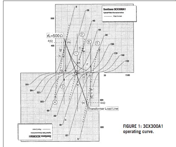
FIGURE 1: 3CX300A1 operating curve.
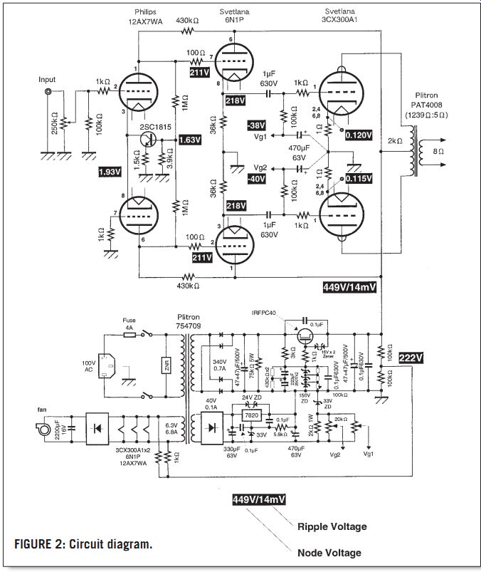
FIGURE 2: Circuit diagram.
condition in his article on graphical analysis for push-pull amps, 2 using the plate curves of the chosen vacuum tubes.
To get this done, I first of all down loaded the Adobe Acrobat (.pdf) file of the 3CX300A1's data from www.svetlana.com. (It is very convenient that Svetlana provides this data at their home page.) Using the .pdf file, I then combined the plate operating curves for push-pull operation (Fig. 1).
In this graph, the grid voltage of the final tube swings between 0V and -84V from the center idle point of -42V. The plate current is at its maximum value when the grid voltage swings to 0V, at the point of intersection with the output transformer's loadline. Thus, the plate load impedance defines the maximum output power.
DEFINING THE LOAD IMPEDANCE
Svetlana recommends a 1.9k plate-to plate load for a 3CX300A1 push-pull amplifier. At the design stage, I was familiar with the PAT4008 toroidal transformer from Plitron's home page at plitron.com. This particular transformer provides a 1239 ohm load impedance with a nominal 5 ohm secondary, so when an 8 ohm load is connected to this tap, the apparent primary impedance is 1k98 ohms fits in excellently with the recommended loading condition.
It is known that the loadline fits onto the operating curve with a slope of one quarter of the transformer impedance.
Thus you can draw the 500 ohm-load impedance line (line m-o-n) over the plate curves, passing through the point O (Fig. 1) at 0mA plate current. Then the reading of plate current at the point m (n) is the maximum, e.g., Imax = 440mA. The maximum output power is determined by the following formula: Po_max. = (Imax/2)2 × rL, giving a value of 48.4W ((0.44 ÷ v2)2 × 500).
CALCULATING AVERAGE PLATE CURRENT OF FINAL TUBES
Formula 25 shown on page 589 of reference 1, Ib = Ibo + (Imax + Imin - 2 × Ibo)/4, gives the average plate current under Class A1 operation.
Since the plate-current characteristic shows 0mA for I_min, this gives Imax = 440mA. And if Ibo = 120mA, the average current is 170mA per tube. So the total average current of this amplifier is 350-360mA 170 × 2 + 10-20).
The power-transformer current capacity of 0.7A AC, with a full-wave bridge rectifier, meets this requirement under the formula IAC = 1.8 × IDC, where IDC_max of the transformer is 389mA (0.7A ÷ 1.8).
MAXIMUM REQUIRED DRIVING VOLTAGE FOR THE FINAL TUBES
It is good to know the maximum driving voltage needed to determine the voltage driver circuit gain. Since the 42V bias volt age was defined by the idle current, this value forces the peak driving value under Class-A operation while avoiding positive drive of the final tubes. Thus the maximum driving voltage is 29.7V RMS (42/v2).
VOLTAGE-DRIVER CIRCUIT AND GAIN
I used the Tube CAD software simulator to determine the parameter values of the driver circuit that give stable operation.
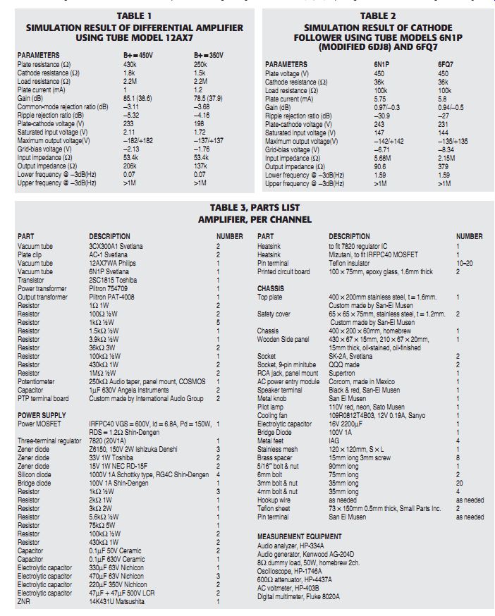
TABLE 1
SIMULATION RESULT OF DIFFERENTIAL AMPLIFIER USING TUBE MODEL 12AX7
TABLE 2
SIMULATION RESULT OF CATHODE FOLLOWER USING TUBE MODELS 6N1P (MODIFIED 6DJ8) AND 6FQ7
TABLE 3, PARTS LIST AMPLIFIER, PER CHANNEL
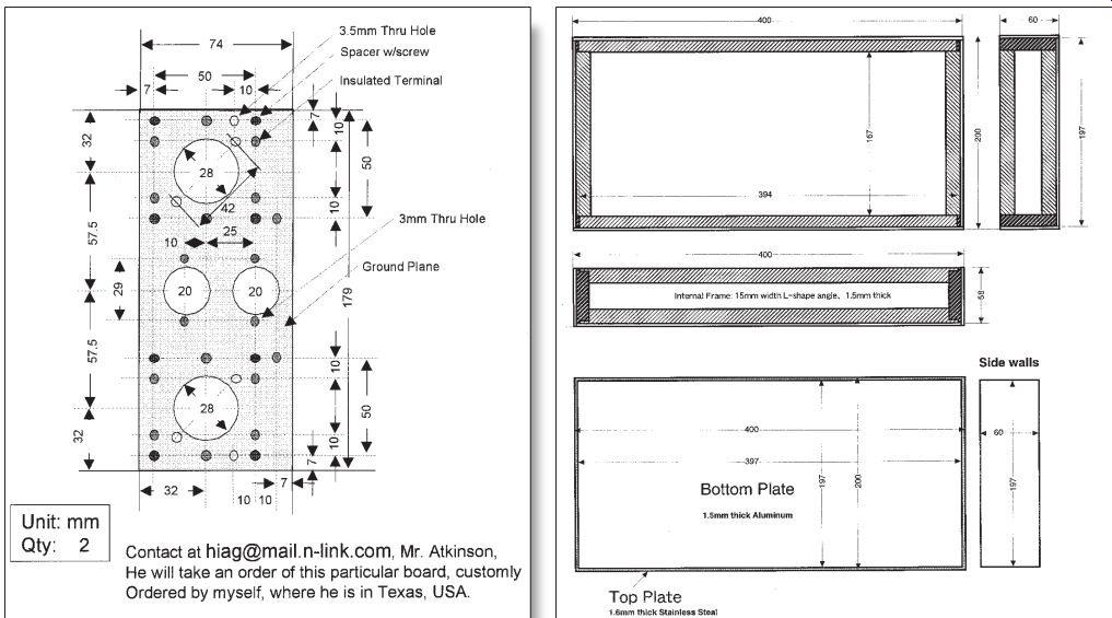
FIGURE 3: PTP terminal board.
FIGURE 4: Chassis internal frame structure.
In general, most existing tube-amplifier designs need a minimum input voltage of 0.5-1.0V RMS to get maximum output power. So the voltage-driver circuit must provide voltage gain between 30(=29.7/1) and 60(29.7/0.5).
CHOOSING THE DRIVER CIRCUIT AND VOLTAGE GAIN
I preferred to use cathode followers to drive the power tubes, since I already knew their good performance. They provide fairly low output impedance, but with a gain of less than 1. Thus the first stage amplifier needs to amplify the input signal of about 0.5 to 1V RMS with a gain between 35 and 40 (30/0.9), then send the amplified signal to the cathode-follower stage, driving the final stage with its pair of 3CX300A1s. The circuit must have a phase-splitting feature for proper push pull drive.
The first stage is a differential amplifier, which generates complementary signals to drive a push-pull circuit easily. A dual-triode tube is ideal for this circuit.
When the other complementary input is grounded, the total gain is approximately 50% less, so the circuit can work as the phase splitter to provide push-pull drive.
First of all, I simulated this differential circuit using a 12AX7, with its high mu of 100, and with a plate supply of 350V, then 450V. The result showed a gain of 78 and 85, respectively. Once the unused input of the differential amplifier is grounded, the total gain would be 35 to 40. Thus, the circuit will meet the requirement for building a phase splitter (Table 1).
Once it was defined, I modified this differential amplifier by using a small signal transistor, such as the 2SC1815, as an active current source, avoiding the need for a negative power supply. Also, this circuit uses the feedback loop from the differential outputs to control the gain. [3] The power-supply voltage is the same 450V as for the final stage, simplifying the internal wiring and assembly.
The cathode-follower circuit uses Svetlana's 6N1P, which has a higher gain than the usual choices, the 6CG7/6FQ7 or 12AU7. This gives a higher voltage gain, closer to 1. The 6N1P also has lower plate resistance, so it saturates the output stage more easily than do the other tubes. The simulation shows a lower output impedance (90 ohm) and higher gain (0.97) than would be obtained with a 6FQ7 (Table 2).
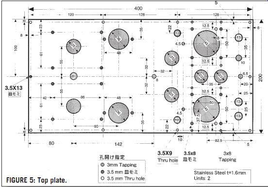
FIGURE 5: Top plate.
The final circuit schematic (Fig. 2) was completed after the foregoing analysis.
The circuit features a differential amplifier using an active current source made with a small signal transistor, and a cathode-follower circuit to drive the outputs.
The fixed-bias circuit brings the -42V bias to the grids of the final tube pair.
COLLECTING THE PARTS
With regard to the parts (Table 3), I prefer to use Plitron's toroidal power trans former, since it features high efficiency, low waste-heat dissipation, and low leak age flux. I also like the wide frequency response provided by the toroidal output transformer, as well as its good damping and good phase characteristics.
The final tubes are a pair of Svetlana made 3CX300A1s, with their unusual shape. Since the 3CX300A1 was originally designed for the high-voltage regulators of Russian radar systems, the maximum plate voltage is a very high 1k8V, and the tube structure itself is, according to Svetlana, very rigid, because of the shape of the ceramic and metal parts. Thus, a final tube-protection circuit using a timer relay is not implemented.
Svetlana's 6N1P is roughly equivalent to the 6DJ8, although its maximum plate voltage is 250V, whereas the original 6DJ8 is only 130V. The 12AU7, 6189W, and 6922 are also similar to the 6N1P, but the output impedances of cathode followers made with those tubes appear to be higher than that of the 6N1P. The first stage 12AX7A is a NOS tube by Philips ECG. The PTP terminal boards, made by International Audio Group (IAG) in Texas, are also used to obtain simplified wiring and easy maintenance. The board is 3.2mm-thick, copper-clad epoxy, featuring a number of turret posts swaged anyplace on the board, as specified by the customer. This structure provides some convenience for simplifying the wiring assembly, as well as shortening the assembly time.
I have suggested to Mr. Atkinson at IAG that they use a copper-clad board instead of a plain board, since I needed a ground plane for easier ground wiring. He accepted this instantly, and the result minimizes hum without using a star-grounding wiring scheme. Thus I love this board, and wish to act as an evangelist. I suggest that audiophiles try to use the IAG boards at least once. They are really neat! If you choose to obtain this board, I suggest you e-mail (hiag@mail.n-link.com) to IAG a pin-placement drawing in Microsoft PowerPoint file (Fig. 3). IAG prefers a clear computer-graphic file when programming its machine, allowing the quickest setup. Even from Japan, I was able to get prompt service. The board came to me in ten days via express mail from Texas. If you would like to use my own board design, you might specify that the board must be identical to mine.
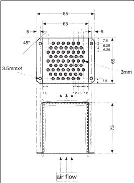
FIGURE 6: Shock proof cover.
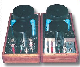
PHOTO 2: Removing a tube cover reveals the internal arrangement of the
tubes.
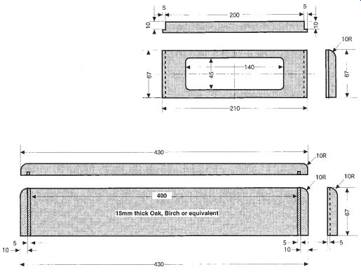
FIGURE 7: Wooden side panel.
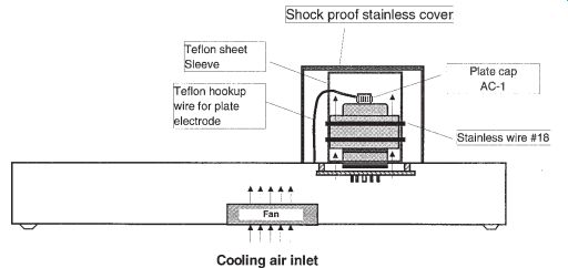
FIGURE 8: Cross section of final tube installation.
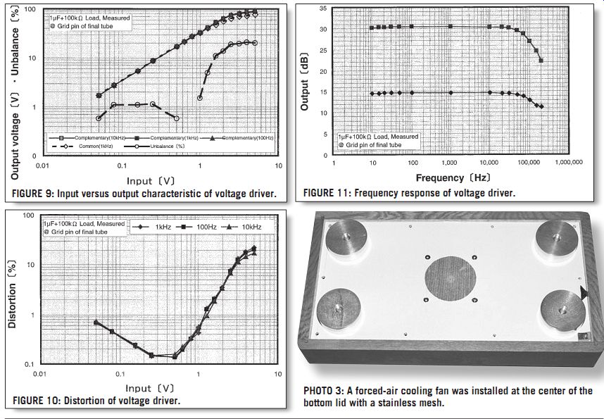
FIGURE 9: Input versus output characteristic of voltage driver.
FIGURE 10: Distortion of voltage driver.
PHOTO 3: A forced-air cooling fan was installed at the center of the bottom lid with a stainless mesh.
FIGURE 11: Frequency response of voltage driver.
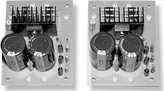
PHOTO 4: The MOSFET and Zener Diode Ripple Filter.
ASSEMBLY
I built the case myself, using pop rivets and other tools (except for the stainless top plate and the protective cover, which were specially made by San-Ei Musen in Akihabara). After assembly, I fixed a 15mm-thick wooden plate, oil-stained and oil-finished, to the sidewall of the case, to give a manufactured appearance (Figs. 4, 5, 6, and 7).
Owing to the professional appearance, the case looks as though it were made by a major manufacturer. I oil-finished the wooden cover three times after oil staining, so that its surface became as smooth as a furniture finish.
I mounted the power-supply board on the internal chassis with a 15mm offset using standoffs. Since the toroidal trans former requires only three small holes to fix it to the top plate, this leaves a lot of room underneath.
Some might say it is very hard to use a ceramic tube like the 3CX300A1 in an audio amplifier, since the tube needs forced-air cooling because of its unique design. As I found, it became very easy to mount these tubes, thanks to the PTP terminal board.
You mount all sockets on top of the board, and then fix the board underneath the top plate with 1cm-tall standoffs.
A 45mm-diameter hole on the top plate provides enough room around each 3CX300A1, so that cooling air comes from the fan installed on the bottom plate, passing only through the tube fins (Fig. 8). To improve cooling efficiency, I put a 0.5mm-thick Teflon sleeve around the tube's fins, winding it firmly with #18 stainless wire. The size of Teflon sheet is approximately 73 × 150mm, so that it covers the sides of the fins and reaches to the same level as the stainless top plate. Thus, no cooling air goes through the gap between the sleeve and the fin, forcing all the air through the top of the tube like a chimney. Over this setup, I used a custom designed stainless hood to protect users against electrical shock and heat (Fig. 6).
The fan generates the forced air. It is installed over the bottom plate, located at the center, and is driven by 7 to 8V DC de rived from the 6.3V AC line for the tube heaters in order to reduce fan noise. A stainless mesh filter is placed over the bottom plate. The structure of the chassis is airtight, so that all the forced air exits through the tube fins.
ADJUSTMENT AND MEASUREMENT
First of all, double-check the internal wiring carefully before inserting the tubes or powering on. Then apply AC power and check the plate-supply voltage with a digital multimeter. It is OK if the plate supply is around 450V, the heater voltage is 6.3V or so, and the fan is working correctly.
(Place your palm over either air outlet on the top cover. The air-flow rate is very low, much less than a hair dryer. The tubes are not running at their full power, so this is adequate airflow.) Then adjust the grid bias trimpot on the top plate so that the grid-bias voltage (measured at the test jack) is roughly -50V. Then temporarily turn off the power switch.
After this initial setup, insert all tubes and turn on the power switch.
Measure the voltage drop across the 1 ohm resistor at the cathode pin of each 3CX300A1, and adjust the grid-bias trimmer so the voltage drop becomes approximately 120mV. Wait for about ten minutes to allow the ceramic tubes to warm-up, since Svetlana says this tube needs several minutes of warm up time. During this period, the cathode-voltage drop is unstable.
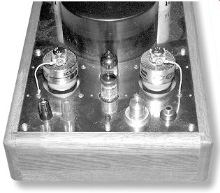
PHOTO 5: Close-up of tube installation.
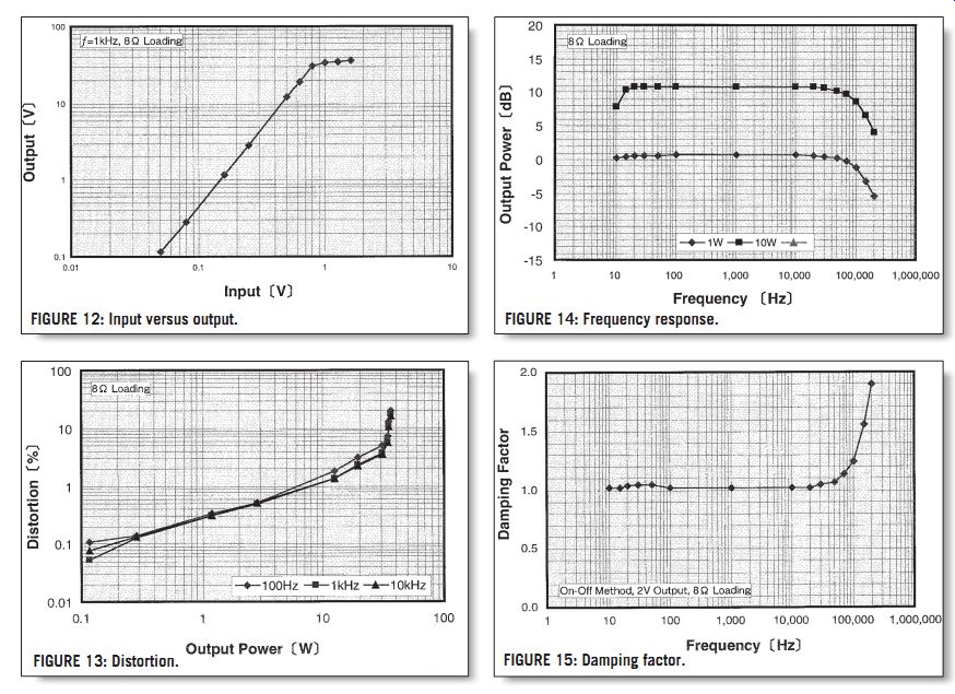
FIGURE 12: Input versus output. FIGURE 13: Distortion. FIGURE 14: Frequency
response. FIGURE 15: Damping factor.
Again, measure the voltage drop across the 1 ohm resistor at the cathode pin of each 3CX300A1; it should still be around 120mV. Then observe the stability of the reading.
A 100Hz square-wave test is all I did for the final adjustment, although an audio signal generator could give more detail and a more precise adjustment. An example is the 100Hz square-wave test that van der Veen has developed.
An oscilloscope allows precise adjustment. Feed the amp with a 100Hz square wave, then observe the square wave at the output, using an 8 ohm dummy load. Adjust the grid-bias volume control so that the output square wave is a perfect rectangle.
Careful adjustment according to this scheme results in minimal imbalance of the idle current, usually less than 1mA when using a matched pair tube.
Originally I used a non-matched pair of 3CX300A1s, since Svetlana does not supply matched pairs at this time. The imbalance of the cathode voltages between the tubes becomes maximum when the output power is at clipping, which can be about 5 to 10mA. This can generate acoustic sound, because the output transformer's toroidal core resonates mechanically at 100Hz. A crazy but workable method for adjusting tube balance suggests itself: adjust the grid-bias volume control so that this audible resonance of the transformer core is minimized.
After adjustment by this method, the idle current of both tubes was 115mA and 120mA, respectively.
OTHER INFORMATION
I finished the adjustment and measurement on the next day. Prior to the measurement, I needed to warm up one amplifier, so I turned the power on. A loud buzzing sound came out of the speaker for a short time.
I had no idea why this happened. To protect my speaker system from possible damage from the buzzing, I disconnected it from the amplifier, leaving the amp to warm up for ten minutes or so. When I reconnected my speakers to the amplifier, the buzz had stopped.
Curious as to why this happened, I sent an e-mail to Eric Barbour at Svetlana and received a prompt reply. His explanation was "Each 3CX300A1 tube has its own warm-up time. The value varies individually, so the deviation of warm-up time may cause imbalance of the plate current. This can cause most or all of the hum and noise in the HV DC supply to appear across the primary of the output transformer, so it does not cancel. This may cause the buzz at the secondary." My curiosity was thoroughly cleared up by his reply.
In addition to this evidence, I found an other cause for the buzz, which came out of the MOSFET ripple-filter circuit. I tested this circuit with an external Sorensen power supply (600V 0.75A DC), which de creased the buzz level better than the internal MOS-FET power supply, and also decreased its duration.
I found that the root cause was the MOSFET ripple-filter circuit. It became "hung up" just after turning on the power.
Approximately 250mA flows out through this circuit into the amplifier, i.e., the output voltage stayed at 420V or so. This was caused by the pinch-off effect of the MOSFET, since a 6V zener diode clamped the voltage across its gate and source electrode.
To eliminate this symptom, I replaced the 6V zener with a 15V zener diode. After this modification, the buzz sound de creased to about one-tenth, though it has not cleared up completely.
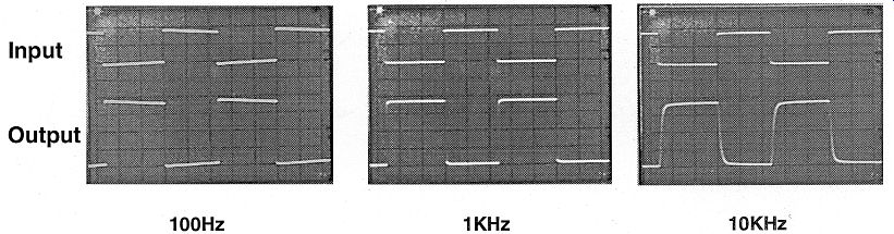
FIGURE 16: Output waveform.
After one amplifier is turned on for 20 seconds or so, this buzzing sound appears, although the other amplifier does not do this. It is tolerable, though I suggest that anyone who hates this buzzing should provide a switching circuit to disconnect the speakers for 30 seconds or so by using a timer relay.
VOLTAGE-DRIVER CHARACTERISTICS- FIGS. 9, 10, 11.
The first stage consists of the differential amplifier, without any AC balancing resistor as is commonly used on long-tail phase-splitter circuits. To verify the well balanced circuit performance of this driver circuit, I measured the characteristics of both outputs of the differential amplifier. Figure 9 shows the results.
The difference in output level at the diff-amp outputs is 1% or less, and mostly zero in the range of 0.6V-1V input level, though it will be over 10% when clipping occurs at approximately 1.5V input. In fact, this differential amplifier works as well as any properly balanced phase-splitter circuit, at less than 1% distortion. Furthermore, its frequency bandwidth extends up to 200kHz at -3dB. The gain of this circuit is about 36, and shows a good match with the simulation result.
OVERALL CHARACTERISTICS
1) Input-to-output characteristic-Fig. 12
Clipping occurs at 0.9V input level, giving a maximum power of 35 to 36W. This does not fit with the calculation result of 48W, but it is close to the initial target.
2) Distortion characteristic-Fig. 13
Measured distortion values are 0.3% at 1W, 1.3-1.5% at 10W, and 3-5% at 30W.
Overall, this is very good performance for a non-NFB amplifier.
3) Frequency response-Fig. 14
The measured frequency bandwidth was beyond 100kHz at 1W output, and even at 10W. This characteristic depends mainly upon the frequency response of the driver stage. According to van der Veen, the Plitron output transformer is capable of a more extended frequency response than this.
4) Damping factor-Fig. 15
The damping factor is relatively low: about 1, through the entire frequency range. In spite of this, the sound is very powerful at low bass, and highs are clear and transparent. This is due to the distinctive characteristic of the Plitron trans former, mainly its excellent damping at frequencies over 100kHz.
5) Output waveforms-Fig. 16
The waveforms are very distinct from those obtained with a conventional E-I cored transformer. This Plitron toroid does not show any overshoot of the square wave at all. Such performance is similar to that of rare and costly old transformers, such as the legendary Acrosound TO series of the 1950s.
As a miscellaneous fact, the output noise and hum levels of the two mono amplifiers, with no input signal, were 0.5mV and 0.6mV, respectively--a very low noise floor.
LISTENING IMPRESSIONS
At last, you reach the final stage of the assembly, after fine-tuning the power sup ply. During the final listening tests, I used a homebrew switch box in alternating two amplifier outputs to compare the sound against the reference, my homebrew 300B single-ended amplifier, which also uses a Plitron output transformer.
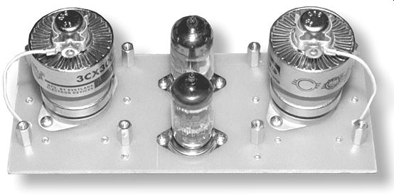
PHOTO 6: All of the tubes neatly sit over the rigid board.
The first impression of the sound is the strong presence in the vocals by female singers such as Rita Coolidge, Natalie Cole, and the like. Compared to a 300B amplifier, I believe the sound of this circuit is stronger, with crisper detail.
According to van der Veen, the sonic difference is caused by the profile of the harmonic distortion (consisting of the even harmonics produced by a single ended amplifier versus odd harmonics made by a push-pull amplifier), as well as by the differences in damping factor.
This amplifier shows a very low damping factor-which is less than one due to the non-NFB circuit. Yet the sound of this amp is very strong and vivid. Overall, I was impressed that this newly introduced Svetlana ceramic tube works so well with this stock Plitron toroidal transformer, and generates such a crisp and powerful sound.
SOURCES
Tec-Sol Inc. (Authorized Dealer in Japan) Hamamatsu-shi, Wada-cho 514 Shizuoka ken, 435-0016 Japan +81-53-468-1201
Fax: +81-53-468-1202 www.tec-sol.com--www.svetlana.com--www.plitron.com Svetlana tubes & Plitron transformers San-Ei Musen Chiyoda-Ku, Soto-Kanda 1-15-16 Radio-Kaikan 4F Tokyo 101 Japan +81-3-3251-7985
Fax: +81-3-3251-2343
Top plate & protection cover, various other parts
Angela Instruments 10830 Guilford Rd., Suite 309
Annapolis Junction, MD 20701 (301) 725-0451
Fax: (301) 725-8823 angela.com/
Angela coupling capacitor International Audio Group Inc.
PO Box 10096 Killeen, TX 76547-0096
Voice/Fax: (254) 699-8702 E-mail: hiag@n-link.com PTP terminal board, metal feet Small Parts, Inc.
13980 N.W. 58th Court PO Box 4650 Miami Lakes, FL 33014-0650
1-800-220-4242 Fax: (305) 558-0509
smallparts.com
Teflon sheet
REFERENCES
1. F. Langford-Smith, Radiotron Designer's Handbook, 1953.
2. Thompson, B.J., "Graphical Determination of Performance of Push-Pull Audio Amplifiers," Proc. I.R.E. 21.4 (April 1933), p. 591.
3. Kevin O'Connor, Principles of Power, Power Press Publishing.
4. John D. Ryder, Electronic Engineering Principles, 1952.
5. Tube CAD manual, Glassware.
Also see: