[This review was written late 2008]
Benchmark Media Systems has developed
an excellent reputation in the professional audio world for their microphone
preamplifiers and digital conversion products. Unlike many “American” companies,
Benchmark not only designs, hut actually manufactures all of their products
in the US, in the upstate New York city of Syracuse. Their DAC1 digital-to-analog
converter has been available for at least four years, and has undergone some
design refinements during that time. The DAC USB is the latest version [ca. late 2008] of that product. (DAC Pre is the latest version).


Above: Front views of the Benchmark DAC USB. The nicely machined aluminum front panel is also available with a silver finish. The rack mount is optional.

FEATURES
The DAC1 USB is a two-channel, 192kHz, 24-bit DAC which has been de signed with Benchmark’s Advanced USB Audio Technology and UltraLock clock system. The headphone jacks are driven by Benchmark’s HPA2TM headphone amplifier (the HPA2 is also used in Benchmark’s H1 headphone amplifier).
The DAC USB has four digital inputs. S/PDIF via a BNC connector; a standard three-pin Neutrik gold-pin XLR connector for AES/EBU; and Toslink optical. What makes the DAC USB unique among outboard D/A converters is the inclusion of a USB connection. You can connect the DA USB to any computer with a USB jack, allowing the user to bypass the mediocre sound cards found in most computers, using the DAC USB as the interface between the computer and monitoring system.
A three-position, spring-loaded front panel toggle switch, combined with three vertically mounted blue LEDs, is used for input switching. The switch simply toggles—up or down—through the various inputs. LED 1 indicates S/PDIF, 2 is AES/EBU, 3 is Toslink, and the USB input is indicated by both LEDs 1 and 3. As supplied, the DAC USB defaults to the USB input at power-up, but you can change the default input to any input by re-setting a jumper on the PC board. The input switching method is simple and well thought out.
The DAC1 USB has no power switch—the unit is intended to be left on at all times, or connected to a switched power line filter. If no digital input is detected for 15 seconds, the unit goes into standby and mutes the audio. The three blue LEDs are also used to indicate input status and errors. For example, 16 slow flashes indicate that no digital signal is present. An invalid sample is indicated by 64 rapid flashes.
When used with the three standard digital inputs, the DAC USB will operate at any input sampling frequency from below 32kHz to above 192kHz, at any word length up to 24-hits. The USB input functions at sampling rates up to 96kHz. You can connect variable-pitch digital sources directly to the Benchmark DAC without any external sample rate conversion. The DAC1 USB supports the Red Book de-emphasis function, at sampling frequencies up to 96kHz, making the unit truly backwards compatible.
The DAC1 USB has unbalanced RCA and balanced XLR line outputs. You can operate these either at a fixed, “calibrated” level or switch them to “variable,” with output level set by the front-panel volume control. The “calibrated” levels are adjustable with 10-turn trimmers. In the variable position the DAC1 USB functions as a preamp line stage, allowing you to connect it directly to a power amplifier with the front-panel pot controlling volume. Users who need multiple line inputs may also consider the DAC1-PRE, which has an extra analog line input.
ADVANCED USB TECHNOLOGY
Benchmark devotes three pages of the instruction manual to discussion of their “Advanced USB Audio Technology.” The DAC USB doesn’t require any drivers in order to operate with Windows Vista/ XP/2000 or Macintosh OS X. Digital data is transported from the computer source to the DAC USB in a bit-trans parent fashion, without any data modification, and without any need to re-configure software.


Above: Inside the DAC1 USB. State-of-the-art digital chips are used, including Analog Devices AD1896 Sample Rate Converter and AD-1853 D/A converter. Construction quality is excellent.
Previous native USB audio devices have been unable to stream audio at any resolution higher than 4SkHz/16- bit. Benchmark’s USB technology allows native USB audio at resolutions up to 96kHz/24-bit. The DAC1 USB will automatically operate with any sampling rate and bit depth being fed to it via the USB port, without reconfiguring drivers (there aren’t any!) and software. Bench mark also buffers the USB datastream to prevent interruptions, which usually rear their ugly heads in the form of clicks and pops.
Benchmark notes that Windows 2000 and XP have a digital mixer known as a “Kmixer” (kernel audio mixer), which passes all audio before it reaches native USB devices. Kmixer contains a poor- quality sample rate converter, but Bench mark’s USB technology allows Kmixer to default to a transparent mode, avoiding the sample rate conversion. Vista’s sample rate converter is of excellent quality and automatically defaults to the highest sample rate supported by the connected device. Nonetheless, you can defeat Vista’s sample rate converter, if desired.
With 16-bit datastreams, the Windows volume control is bit-transparent only when set to full volume. But, Benchmark discovered that the Windows volume control is distortion free when streaming 24-bit datastreams. The DAC1 USB forces Kmixer to stream 24-bits so the Windows volume control doesn’t degrade the audio quality. Benchmark also found that the Mac OS X volume control has poor quality sample rate conversion, and the system volume control degrades the audio unless it’s set to maximum. OS X is capable of bit-transparent audio if the sample rate is manually set to match that of the audio being played, and the system volume control is set to 100% (use the volume control on the DAC1 USB). For more information on PC audio, go to benchmarkmedia.com.
JITTER CONCERNS
Benchmark is extremely concerned with the effects of clock jitter on audio performance. Better D/A converters, sample rate converters, and outboard jitter suppressors have generally employed two- stage phase-locked loops for improved jitter suppression, including my reference sample rate converter, a Parts Connection Assemblage D2D-1 (discontinued).
Benchmark claims that their UltraLock clock system exceeds the jitter performance of conventional two-stage PLL circuits.
The UltraLock system isolates the conversion clock from the digital audio interface clock, so jitter on any digital input can’t have any measurable effect on conversion clock jitter. With this system, interface jitter will not degrade the conversion process. The DAC1 USB manual has an interesting and informative discussion of jitter, including two problems that are rarely discussed. One is that jitter causes phase modulation of the audio signal, producing unwanted sidebands on either side of every discrete tone in the audio signal. These sidebands are unrelated to the audio signal and are easy to hear and measure. Benchmark also says that jitter can severely degrade the digital anti-aliasing filters in an oversampling converter. Though seldom considered, they note that this effect is also easily measurable: The UltraLock system puts clock jitter below the measurement limit of the Audio Precision System 2.
DESIGN DETAILS
The DAC1 USB is not supplied with a schematic, but a look inside reveals most of the design details. Digital in puts are routed to an AK Semiconductor AKM4114 Digital Audio Interface, which includes the input receiver. The AKM4114 has eight digital inputs, and includes a low-jitter analog phase-locked loop with a lock range of 32kHz to 192kHz. The S/PDIF and AES/EBU inputs are each coupled with their own pulse transformer.
I don’t see any evidence of input switching near the digital inputs—it appears that each input, including the Toslink and USB (after its own interfacing), is fed directly to one of the eight in puts on the AKM4114. This is very sensible, because the internal input switching of the AKM4114 probably results in lower clock jitter than external input switching. This capability is a compelling reason to use the AKM4114 for multiple digital inputs.
The j2 output of the AKM4114 is fed to an Analog Devices AD1896 High Performance Asynchronous Sample Rate Converter. The AD1896 is the current flagship asynchronous converter chip from Analog Devices and boasts THD+N of -120dB and DNR (with filter) of -139dB. The AD1896 can convert any input sample frequency to any other, up to 192kHz. In the Benchmark DAC1 USB, the AD1896 is set up to convert all inputs to a sampling frequency of 110kHz, which Benchmark has found to be optimum.
The 110kHz output of the AD1896 is fed to Analog Devices’ AD 1853 DAC, a 24-bit stereo, multi-bit, Delta/Sigma converter chip operating at sampling frequencies up to 192kHz. De-emphasis, if needed, is performed in the AD1853.The DAC chip’s differential current outputs are fed to 5532 dual op amps, which may seem an odd choice for current-to-voltage conversion these days. The DAC1 pre uses an LM4562 op amp throughout.
With a noise level of 5nV/ the 5532’s low noise level and low cost still makes it attractive to some designers. Yet in other regards, particularly slew rate and bandwidth, there are many other chips that would seem more suitable for high- performance designs in 2008. The Burr- Brown/TI 0PA627 has even lower noise than the 5532—4.5nV_/Hz a slew rate of 55V/uS, and a gain-bandwidth product of 16MHz. By comparison, the 5532 has a slew rate of 9V/ and a gain-band width product of 10MHz.
Analog Devices recommends the OP275 for I/V conversion and differential-to-single-ended conversion on page 15 of the AD-1853 datasheet. Benchmark seems to be using a topology similar to that recommended by AD. Another 5532 (one half per channel), rather than an OP275, also appears to be used for the differential-to-single-ended conversion (doubling as an output buffer). The analog filter in the AD datasheet is a Gaussian type with a -3dB point of 75kHz. I really don’t understand why Benchmark chose a device as dated as the 5532 for use with a state-of-the-art DAC such as the AD1853.
(Note from the Manufacturer: The 5532s were chosen because, unlike most substitutes, they do not exhibit a rise in the THD with frequency above 20kHz. This prevents intermodulation distortion caused by ultrasonic audio content.)
The unbalanced outputs are driven by National Semiconductor LM4562 dual op amps, with a 5532 used as unity gain buffers for the two channels. Similarly, the balanced outputs are also driven with LM4562s (one per channel, in this case’), with a 5532 again used as the DC servo. Only one 5532 is used for both balanced output channels. I suspect that, for each channel, half of a 5532 is used as a servo amp around the first half of an LM4562, which feeds the second half of the LM4562 configured as inverting amplifier to form the other leg of the balanced output.
The LM4562 was designed as a high- performance audio device and boasts THD of 0.00003% into 600 loads. Slew rate is 20V/ gain-bandwidth product is 55MHz, and noise is exceptionally low at 2.7nV_/Hz. I would think that the LM4562 would also have been an excellent choice in the other places where Benchmark used the 5532.
The two headphone jacks appear to be driven by the same amplifier. The only difference is that one of the jacks can be configured to cut off the line outputs on the rear panel, while the other always leaves them on. The headphone amp has a pair of 5532 op amps and two Burr-Brown/TI BUF634 buffer amplifiers.
The BUF634 is an outstanding device capable of 250mA of output current, albeit with considerably more heatsinking than it’s given in the DAC1 USB. Bench mark has used the five-lead DDPAK surface-mount package, with a small piece of ground-isolated PC land providing some additional heatsinking beyond the devices’ own metal tab. For each channel, half of a 5532 provides the gain, buffered by a BUF634, with the other half of the 5532 operating as a DC servo amp.
(Note from Manufacturer: The PCB is designed as a heatsink. This is extremely effective, and can be shorted all day with out overheating.)
Benchmark notes that the headphone amplifier design has an output impedance of 0-ohm -- the BUF634 is connected directly to the headset without the usual series resistors. Resistors will degrade the performance of any headphone amplifier; if the headphone does not have a flat impedance curve, the series resistor will change the headphone’s frequency response. The amplifier will drive headphones with impedances as low as 30-ohm maintaining less than 0.00003% THD+N.
Fixed, three-terminal 7818A and 7918A regulators are used for the ±18V analog supplies (see Chuck Hansen’s comments on supply voltages in the measurements portion of this review). Two digital regulators are also used, a 7805 for the 5V supply and an LM1085 for the 3.3V supply. Separate rectifier bridges are used for the analog and digital supplies, fed by separate windings on the toroidal power transformer. Most resistors and capacitors are surface-mount “chip” type, except for the electrolytics. The DAC1 USB doesn’t contain any passive parts normally thought of as “audiophile” grade.
PERFORMANCE
Chuck Hansen’s accompanying measurements show the DAC1 USB to be beyond reproach. Indeed, its measured performance taxes most available test equipment, short of an Audio Precision System 2. The System 2 is used in-house by Benchmark, and the manual contains their own set of measurements performed on the Audio Precision instrument.
Given the data collected by Chuck, there’s no reason to doubt the outstanding measurements published by the manufacturer (Benchmark also includes jitter tests with their measurements). The printed manual supplied with the DAC1 USB is also available on Benchmark’s website. I suggest downloading this version of the manual, because all illustrations and photos are in color.
I have been using theDAC1 USB in my office playback system at The Crane School of Music, SUNY Potsdam, for about two months. During the time I’ve had the DAC1 USB connected to my office system, I’ve heard dozens of my own Crane recordings on this DAC (most made with Schoepps MSTC-5 or MSTC-6 ORTF stereo microphones, a Millennia HV3B microphone preamplifier, and Tascam DV-RW1000HD digital recorders). All I can say is that I simply hear much more in my recording than before—more detail, improved low-level resolution, better dynamics, ‘and a bigger soundstage with more precise localization.
I also installed the Benchmark DAC in my home audio system for a week, where I compared it to my recently purchased NAD M55 multi-format player used as a standalone device. The M55 also served as the transport f the DAC1USB. I also compared the DAC1 USB to the Monarchy M24s.
The DAC1 USB is the most transparent DAC I’ve auditioned. CDs and DVDs are reproduced with pristine clarity. The sonic picture is detailed and spacious. Soundstaging is incredibly precise, with a large amount of hall ambience in the rear of the stage. On the Munch recording of Dukas’ The Sorcerer’s Apprentice, the violins playing harmonics at the beginning were reproduced with a delicacy that I’ve not heard previously on this recording.
The cymbals in Fritz Reiner’s Pictures at an Exhibition are crisp and inner detail in tutti passages is exceptional. The Mercury recording of Respighi’s The Birds is clean, detailed, and transparent. Strings articulation is excellent in both recordings. Precision is a word that continually comes to mind in listening to the DAC1 USB.
The Benchmark DAC was definitely designed with accuracy in mind, rather than euphony. In the Mercury recording of Respighi’s The Birds, the NAD M55 as a standalone player sounds slightly warmer and sweeter, while the Bench mark sounds more analytical and more transparent. In the Classic Records DVD of Rachmaninoff’s Symphonic Dances, the DAC1 USB sounds more transparent and more detailed, and the M55 again warmer and sweeter.
In the Reiner Pictures, the DAC1 USB is leaner, with the sonic picture reproduced with exceptional precision. This is especially true in the passage for the glissandi strings in “Gnomus” where the Benchmark’s localization of each string section is more precisely focused than I’ve ever heard. Again, the M55 sounds warmer, with perhaps a bit more weight in the bottom octave.
In general, the comparisons I’ve made between the Benchmark DAC and the NAD M55 as a standalone also apply to the Benchmark versus the Monarchy M24. The Monarchy M24 was designed with a bit of euphonic coloration rather than absolute accuracy The NAD M55 as a standalone player leans more toward the Monarchy M24 than the Benchmark.
I have only two criticisms of the DAC1 USB. Tonally, the Benchmark DAC is neutral except for a tendency toward brightness. Normally, the Benchmark DAC is never fatiguing, but the brightness doesn’t always flatter already bright recordings such as Dorati’s Mercury CD of Schoenberg’s Five Pieces for Orchestra. The violin section in the Classic Records DVD of Stokowski’s Everest recording of “Wotan’s Farewell” from Wagner’s Die Walküre is also brighter than I’d like, but the inner detail is also exceptional. It doesn’t help that the Houston Symphony’s strings were well below world-class standards in 1960.
Violin sections in orchestral recordings are not as sweet as the real thing. Given that the digital end of this DAC is practically beyond reproach, I can’t help asking whether the DAC1 USB would sound even better if Benchmark would replace the 5532 op amps with another device. I think that the National Semiconductor LM4562 used for the analog output stages would be an improvement over the 5532 in other locations as well. That said, I would never have guessed, based on listening, that there were any 5532 op amps in this device had I not known better.
I’ve never heard a product with 5532 op amps sound this good. Could the Texas Instruments 5532 op amps be audibly superior to the types made by NJR and other Far East sources, and used in so many mid-fl products? Or, is the digital end so good that the use of 5532s isn’t that detrimental? Still, I wonder what the Benchmark DAC would sound like with LM4562s used throughout.
Connecting the DAC1 USB to a computer couldn’t be simpler. Plug it into a USB port and Windows will recognize it within seconds. Sonically, the difference between the Benchmark DAC and my computer sound card is astonishing. If you do a lot of digital editing, the ability to really hear what’s on your editor will be most welcome. I have permanently installed the DAC1 USB with my computer editing system at work.
JITTER ELIMINATION?
I still use my Parts Connection D2D- 1 Sample Rate Converter between the NAD M55 and Monarchy M24 DAC. Despite the dual phase-locked loop around the input receiver, and excellent jitter suppression properties of the built- in asynchronous sample rate converter, the D2D-1 has never eliminated sonic differences between various transports. My NAD M55 is the best-sounding transport (and the best-sounding stand alone player) that I’ve owned. As a transport feeding the D2D-1, it is noticeably cleaner and more transparent than my older Onkyo DV-SP800 multi-format player, which, in turn, is better than the comparatively foggy Marantz PMD-340 CD player. As a transport, the Marantz sounds quite unrefined compared to the Onkyo and, especially, the NAD. Jitter is the only reasonable explanation for differences in the sound of various transports, and as good as the D2D-1 is, it must not be eliminating jitter, just reducing it.
Enter the DAC1 USB. My listening evaluations would indicate that Bench mark’s claims for the jitter performance of the DAC1 USB are justified. I spent one evening comparing the NAD M55 and the Marantz PMD 340, with the NAD connected to the Benchmark’s SI PDIF coax input (with D.H. Labs D-75 digital interconnect fitted with Canare 75 BNC connectors) and the Marantz connected to the AES/EBU input (D.H. Labs D-110 digital interconnect and Neutrik gold-pin XLR connectors). This made it easy to go back and forth between the two transports by simply switching the DAC1 USB’s input selector and moving the reference CD to the other transport.
PHOTO 3: Rear view of the Benchmark DAC. S/PDIF, AES/EBU, and Toslink optical inputs are provided, along with a USB connection. Balanced and unbalanced analog outputs are also included.
For the first time since I began evaluating digital hardware, I can honestly say that I found it difficult to tell the difference between two transports. The old, relatively unrefined Marantz sounded excellent connected to the DAC USB—spacious, detailed, and refined. There were times when I thought that the NAD M55 sounds slightly better— perhaps a shade better defined with the stereo image a bit more precise. Occasionally, I thought the Marantz sounded a bit mushy and the NAD crisper, the Marantz a little edgy in the treble and the NAD smoother. Then, I’d run another comparison and not be so sure of my conclusions.
The bottom line is that the Bench mark DAC reduces jitter to vanishingly low levels—measurably and audibly—to the point where even a transport that would normally not qualify as “audiophile” sounds excellent. If there are differences between my NAD and Marantz transports, those differences are very small, indeed. This is most impressive.
It almost goes without saying that any outboard jitter suppressor connected between your transport and the DAC 1 USB is superfluous. I inserted my D2D-1 between the NAD M55 and the DAC1 USB to see whether this had any effect on the sound. I left the D2D-1 in the “Transparent” mode, so it was functioning strictly as a jitter suppressor, without any sample rate conversion. By simply swapping digital cables, it was easy to remove and re-connect the D2D-1.
The results were similar to comparison of transports, except this time I really was convinced that there was an audible difference, even though it was very subtle. The D2D-1 degraded the sound very slightly. It caused a slight loss of focus and detail and put a very subtle veil over the sound. It also softened the treble slightly. Benchmark has shown that it’s possible to design a DAC so that external jitter suppression devices are no longer necessary or desirable.
CONCLUSIONS
The Benchmark DAC1 USB is an impressive achievement—an exceptionally refined DAC that offers remarkable performance at an extremely reasonable price. Benchmark’s UltraLock circuitry sets new standards for jitter suppression, and the USB interface provides a significant improvement over monitoring via computer sound cards. Benchmark offers a 30-day, risk-free trial period. If you’re in the market for an outboard DAC, you can’t afford not to try one.
TABLE 1 Reference Recordings (not shown)
Measurements for the Benchmark DAC1 USB
SETUP
I used a 75-ohm coax cable between my Alesis ML-9600 Masterlink recorder digital output terminated with a 75-ohm BNC female to male RCA adapter, and the Benchmark DAC1 USB AES/SPDIF 75-ohm BNC Input 1. While the DAC1 comes with an RCA female to 75-ohm BNC male adapter to use with a conventional digital audio cable that is terminated on both ends with RCA plugs, I prefer to treat the digital AES/ SPDIF signal as an RF signal (which it is) and use the 75c2 BNC terminated cable with my BNC to RCA adapter. I applaud Benchmark for providing the 75Q BNC digital connector on the DAC1, and I would like to see it become standard in lieu of the inferior RCA jack.
CAUTION: Never use a 50-ohm BNC plug on the DAC1 digital 75-ohm BNC input jack. The center pin of a 50-ohm BNC plug is slightly larger in diameter than that of a 75-ohm BNC plug, and you could permanently expand the 75-ohm female input pin enough that it will no longer make good contact with a 75-ohm BNC plug center pin.
In order to provide a suitable warm up before testing, I played over one hour of 16-bit and 24-bit audio test tracks. The DAC1 USB easily locked onto 16-bit 44.1kHz digital signals, as well as 48kHz, 88.2kHz, and 96kHz 16-bit to 24-bit signals (I don’t have any 192kHz digital test data). There is no indication of the received data bit depth or sample rate on the front panel. If there is an error in acquiring digital data, the input LEDs on the front panel will flash to reveal various data error codes as listed in the very thorough instruction manual.
The DAC1 USB provides many internal jumper-selected settings, but I left them all as-received. I also left the rear panel Output Level switch in the calibrated (fixed output) position. I did not attempt to control the DAC1 USB by means of a computer connected to the USB port. The unit uses linear IC voltage regulators rather than a switching power supply, so the case temperature increased from 25° C to 36° C at the bottom of the chassis.
The DAC1 USB preserves normal polarity from all its analog outputs. The RCA jack analog outputs produced 2.004V RMS (L) and 2.007V RMS (R) at 1kHz, or an insignificant 0.03dB maximum above the Red Book Standard of 2V RMS. The balanced XLR outputs both produced 1.267V RMS (pin 2 hot) with the internal attenuation jumper left unchanged. The headphone output at the maximum volume control setting is 2.87V RMS at 1kHz, with about 0.4dB imbalance between the two headphone jacks at the unity gain setting. The volume control does not operate on the balanced or unbalanced RCA outputs in calibrated mode.

FIGURE 1: Frequency response.
FIGURE 2: De-emphasis error.
FIGURE 3: THD+N vs. frequency.
MEASUREMENTS
The output impedance of the RCA jack analog outputs measured 29 at 20Hz and 1kHz, increasing slightly to 31-ohm at 20kHz. The balanced XLR outputs measured 133 ohm over the audio band (this will vary with the attenuator jumper settings). The front panel headphone output measured less than 1 ohm with the volume control set for unity gain.
Hum and noise measured a low -110dB relative to 2V RMS, and -116dB A-weighted. The analog outputs had a negligible DC offset of 3.4mV. Separation between the stereo channels was about -105dB at 10kHz.
I recorded the frequency response shown in Fig. 1 from the RCA analog outputs into 100k and 300 ohm loads, using 16-bit/44.lkHz Red Book data as well as 24/48kHz and 24/96kHz data. The DAC1 USB response drops off by -0.23dB at 20kHz (44.1kHz data), and -0.81dB at 43kHz (96kHz data). When I decreased the line stage load to a difficult 300-ohm the frequency response fell by -0.84dB at 1kHz, with a slight droop at 10Hz with 16/44.1kHz data.
Figure 2 shows the deviation from flat response when I fed pre-emphasized Red Book 16/44.1kHz digital data to the digital input. The de-emphasis correction is accurate ±0.09dB, 20Hz to 20kHz.
The THD+N versus frequency for the DAC1 USB RCA analog outputs using 16/44.1kHz digital data is shown in Fig. 3. I used the steep distortion test set 22kHz low-pass filter to remove out-of-band noise. Note that the results shown here are just about at the low limit of my distortion measurement capability. Decreasing the load from 100k to 3001 showed only a slight increase in THD+N. The headphone output with a 32 load is shown as a dashed line. This is all-around excellent performance.
Figure 4 shows THD+N versus output voltage for the RCA output into 100k at 1kHz. The THD+N level increases in a straight line as the output level decreases, up to the 0.5% vertical axis limit in my graph.
The DAC1 USB output spectrum of a 50Hz sine wave at 0dBfs into 100k is shown in Fig. 5, from zero to 1.3kHz. The THD+N measured 0.0027%, with no visible harmonics above the -105dB noise floor of my spectrum analyzer. Raising the frequency to 1kHz and expanding the spectrum range to 20.5kHz shows a similar benign result (not shown).
The distortion residual waveform for a 0dBfs 1kHz sine wave, taken after the distortion test set notch filter, showed no discernible distortion harmonics or AC power line artifacts and just a low level of noise (also not shown).

FIGURE 4: THD+N vs. output.

FIGURE 5: Spectrum of 50Hz sine wave.
FIGURE 6: 11kHz + 12kHz intermodulation distortion.
FIGURE 7: 19kHz + 20kHz intermodulation distortion.

FIGURE 8: 1kHz square wave, 16/44.1 data.
FIGURE 9: 1kHz square wave, 24/96 data.
FIGURE 10: 1kHz sine wave at -90.3dBfs with 16/44.1 data.
Figure 6 shows the DAC1 USB output spectrum reproducing a combined 11kHz + 12kHz intermodulation distortion (IMD) signal at 0dBfs into 100k-ohm. The 1kHz IMD product is -95dB (0.0018%). Repeating the test with a 19kHz + 20kHz CCIF IMD test signal (Fig. 7) resulted in a -102dBfs 1kHz product (0.0008%).
I applied a 1kHz square wave at 0dBfs, 16/44.1kHz digital data to the DAC1 USB and monitored the resulting scope trace from the DAC1 USB (Fig. 8). The Gibbs Phenomenon ringing is unremarkable except for the slight leading edge damped oscillation. Increasing the digital data to 24/96kHz (Fig. 9) showed a better representation of the square wave, with a bit higher peaking on the leading edges.
The reproduction of a 1kHz sine wave at -90.3dBfs with 16/44.1kHz data is shown in Fig. 10. The sine wave at this ±1 bit signal level appears as three distinct levels, just as it should. Increasing the data resolution to 24/96kHz at -90.3dBfs produces the fine sinusoidal shape shown in Fig. 11.
The DAC1 USB produced an excellent set of measurements. The instruction manual includes 15 pages of test graphs provided by an Audio Precision System 2 Cascade.
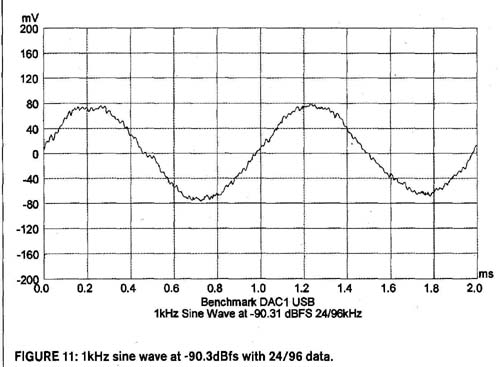
FIGURE 11: 1kHz sine wave at -90.3dBfs with 24/96 data.
POWER SUPPLY CONCERNS
I removed the cover to take a look at the PC board since the instructions to get internal access were in the instruction manual. I was a bit alarmed to see that the analog IC regulators are ±18V (7818A and 7918A). This is fine for the 5532 op amps (±20V maximum), but the LM4562 op amps and the BUF634s have an absolute maximum rating of ±18V. I didn’t see any other local lower voltage PC board mounted regulator chips, nor a -5V regulator IC that might be teamed with the 7805A for a ±5V supply for the op amps and buffer ICs. This is not really possible, because the maximum headphone output is specified to be +21dBu (8.69V RMS) and the balanced outputs are specified to be +29dBu, or 21.8V RMS.
I did not attempt to measure the actual voltages at the op amp supply pins, but the ±18V regulators raise a red flag for me if those parts are actually used at ±1SV (or even higher, since the tolerance on 78xxA and 79xxA regulators is 2% at 25° C, or 4% over the full temperature range). My absolute safe maximum for any analog IC is 90% of maximum rated, or ±16.2V in this case.
The reason I use 90% is because that’s the maximum number that both MIL-HDBK-217 and the Telecordia (Bellcore) TR-332 “Reliability Prediction Procedure for Electronic Equipment” have in their MTBF calculations. I work pretty close with both documents and talk with the guys who have cognizance over the military handbook, and they say if you go above 90% for semiconductors, you are conducting experiments, not pro viding suitable power for long-term reliable operation of analog ICs and semiconductors. Calculated MTBF effectively becomes zero hours above 90% Vcc. Except for passive phono preamps that require lots of headroom to make up for the loss through the EQ stages, there is rarely any need for more than 2V RMS output to a power amp, so ±15V DC rails should be fine.
Another review: 6moons
Also see:
THE SWEET SPOT--This master circuit designer reveals some secrets at the component level to achieving the best possible sound in your audio amps.