You can use this "Tri-Way" power supply--a three-output regulated supply--for a variety of applications.
This is the second in a series of multiple-purpose power supply boards which began with the Gamp (article coming soon!). That board was intended primarily for low-power tubed projects, and used passive filtering (although it could be adapted to add regulation).
This board was designed for a different class of projects: solid-state designs using regulated ± supplies to feed amplifying circuits (discrete or integrated), plus a third positive supply which could feed phantom-powered microphones, logic circuits, or relays. Partway through the design process, I realized that with a few extra jumpers the same board could be used to feed regulated DC to the filaments of tubed projects, while still retaining that extra supply for phantom, logic, and so on.
Digging further, I designed the board so that Supplies 1 and 2 could be fed by a center-tapped transformer, by a single transformer with separate secondary windings, or by two separate transformers. This opened the way toward using the board with wall-wart transformers, useful for meeting UL specifications Using separate windings or transformers, in turn, provides the ability to float Supply 2 (or 3), elevating the filament above ground to avoid exceeding a tube’s heater-to-cathode voltage limits.
JOB DESCRIPTION
As always, I began by listing what I expected the design to do:
1. Provide up to ±30V DC, regulated, from Supplies 1 and 2, at current levels up to 1.2A, for solid-state preamplifier and signal-processing circuits.
2. Provide separate regulated voltages up to 30V DC from Supplies 1 and 2 for use with tube filaments.
3. Allow Supply 2 to be floated up to +75V DC above ground.
4. Provide up to +48V DC regulated voltage from Supply 3, at up to 0.5A, for microphone phantom-power sup plies, logic circuits, and relays.
In the course of doing those jobs, the board should:
1. Filter out ripple.
2. Filter out line garbage.
3. Minimize diode-switching noise.
4. Provide properly-regulated output voltages when line voltage dips down to 10% below nominal, and avoid fried components when the line voltage runs 10% above nominal.
5. Minimize component stress under ad verse conditions, including hot working environments ( Missouri summers are legendary).
6. Be usable with one, two, or three external transformers (wall-warts) if needed.
7. Allow off-board regulators for high- current designs.
I added one refinement during the design process: I made the board in two halves, with a cut line. This means you can use it as a single 5 x 5” board, with raw supplies and regulators together in the cabinet, or separate the raw sup ply section and mount it in an external power pack, useful for keeping hum- radiating transformers away from audio circuits. I designed the two halves so that each would fit vertically into a 2U rack chassis.
DECISIONS
Once I’d settled on the board’s requirements, I had two more major decisions: what level of regulation would the board provide, and what sort of passive filtering would precede the regulators?
After a few decades, I’ve decided that for solid-state audio circuits (particularly IC op amps), the level of regulation provided by adjustable IC regulators such as the LM317/337 is the minimum for good sound. In my experience, designs which use three-terminal fixed voltage regulators (78xx/79xx) don’t sound as good as designs with LM317/337 regulation or better. Walter Jung has published tests comparing the technical performance of fixed and adjustable IC regulators, along with fancier circuits, and in virtually every respect the adjustable devices outclassed the fixed-voltage chips
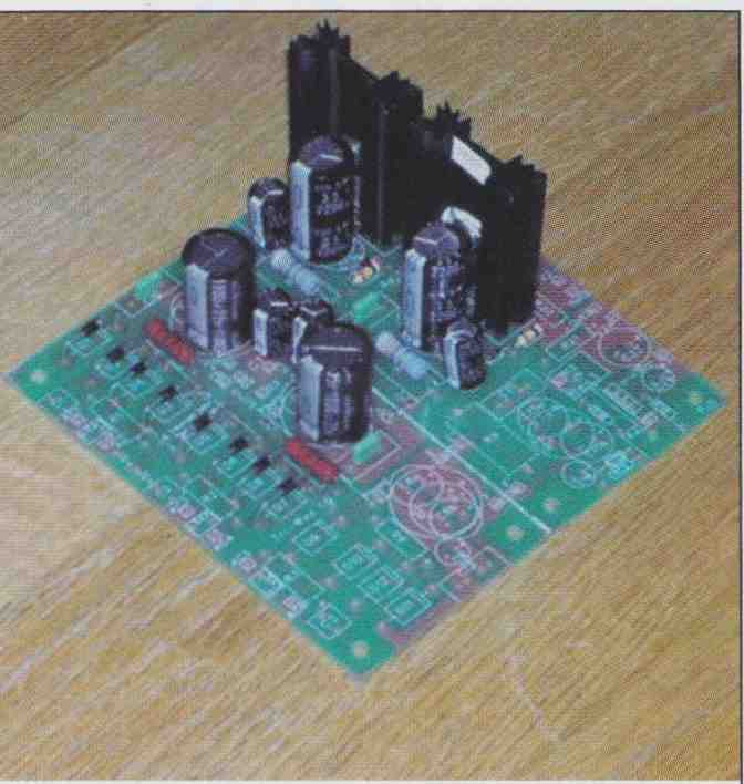
PHOTO 1: The Tri-Way board, with most of the parts installed for use in
a compressor.
So the regulators would be LM317/337 chips; for phantom power, the TL783 chip (which has the same pinout as an LM317) would work fine. What about higher performance? For those who want tighter regulation, lower dropout, and other improvements, LT1085/1033 devices are pin-compatible with LM317/337s; they’ll work fine on this board, too. The best regulation comes from op amp-based circuits like the ones designed by Michael Sulzer and Walter Jung I like to put regulators such as those onto the audio boards rather than the supply card The Tri-Way card’s Supplies 1 and 2 make good pre-regulators for this type of design.
What about passive filtering before the regulators? I chose to use two-stage RC filters rather than single capacitors. A properly-designed two-stage filter lets through less ripple than a single stage with the same total capacitance, and using a smaller input capacitor decreases the strain on the rectifiers at turn-on.
Two-stage filters are also more versa tile for home constructors. Manufacturers can specify exactly what voltage a transformer should supply; home builders don’t get to do that, but must use off-the-shelf stock values. A two-stage filter lets you design for whatever transformers are actually available, then drop extra voltage in the resistor (rather than stressing the regulator).
A two-stage filter made from smaller caps can also be more effective in filtering out switching noise and line junk, as smaller electrolytic capacitors remain capacitative out to a higher frequency. If you’re separating the raw supply from the regulated, using an external box for the raw section, the second stage of filtering (which is on the regulator half of the. board) will filter out any additional garbage picked up by the umbilicus that connects the two boxes.
As I’ve mentioned elsewhere, I’m a fan of Ben Duncan’s ideas about de signing anti-resonant power supplies to keep diode and line-borne noise away from audio circuits To those ends, I used fast-switching diodes and snubbers to minimize noise generation, bypassed filter capacitors with smaller electrolytics and film caps, and placed a small resistor between the rectifiers and the first filter cap. Jumping ahead a bit, I followed Duncan’s suggestion and used 1N4148s as regulator safety diodes, along with current-limiting resistors; these are less likely to conduct high-frequency crud around the regulators. I also left room for adding surge absorbers across the transformer secondaries, which can help long-term reliability in this age of not-quite-stable wall current.
Finally, I made room for the grounding system I often prefer to pure star-ground: the grounded end of the regulator circuit(s) goes to the load ground, which, in turn, sends a separate wire to main system ground. Most of the time I find this provides a quieter supply.
JUMPING JACKS
Take a look at Fig. 1. Perhaps the most salient feature of this design is that it has a lot of jumpers.
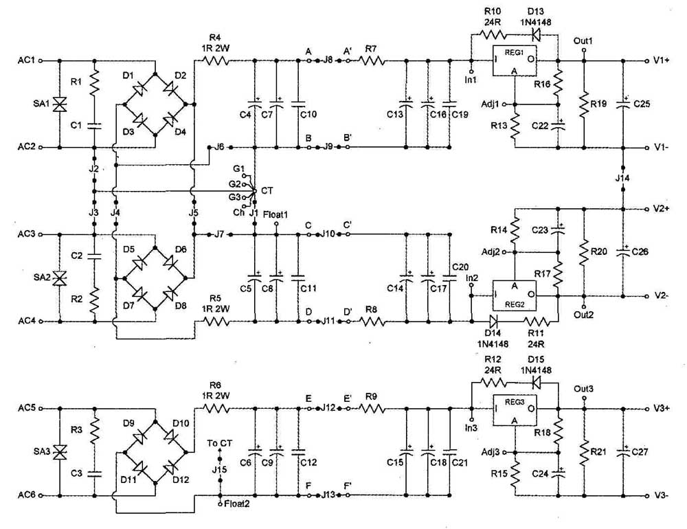
FIGURE 1: Tri-Way supply, basic schematic.
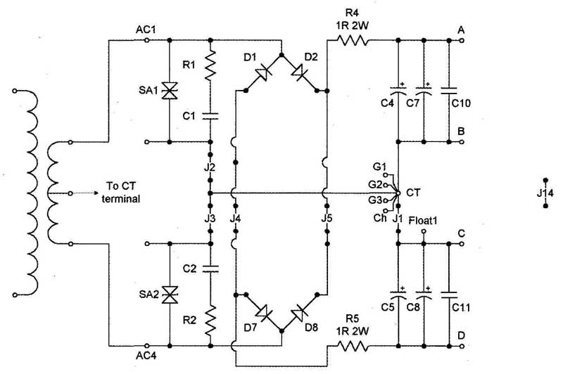
FIGURE 2A: Supplies 1 and 2 input section hookup with center-tapped transformer.
Note use of J14.
Let’s take the easiest ones first: J8-13 connect the input half of the board (snubbers, rectifiers, first filter section) to the output half (second filter section, regulators). When the board is used in one piece, these jumpers are simply short lengths of l8ga wire. If you split the board, however, and put the trans formers and input section in a separate power pack, the jumpers become wires in an umbilical cable, which connects the boxes.
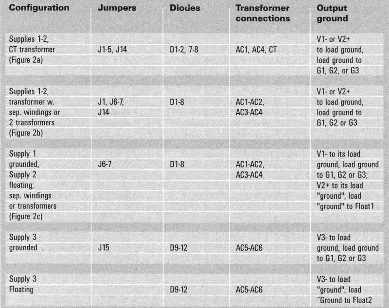
Jumpers 1-7 select the transformer type and circuit configuration of Supplies 1 and 2. Take a look at Table 1, which offers several possibilities:
1. ± voltage, center-tapped transformer (Fig. 2A). In this hookup, you’d connect the transformer’s center-tap to the CT terminal on the board (duh). This produces a full-wave bridge rectifier while permitting separate snubbers for the two halves of the transformer. J1 connects the two supplies’ ground sections together, producing the main power supply ground point, while J14 ties the two regulators’ ground points together, to feed the load ground.
2. ± voltage, separate windings or transformers (Fig. 2B). This is the configuration I recommend when the transformers are AC wall-warts. Again, J1 and J14 tie the plus and minus halves together.
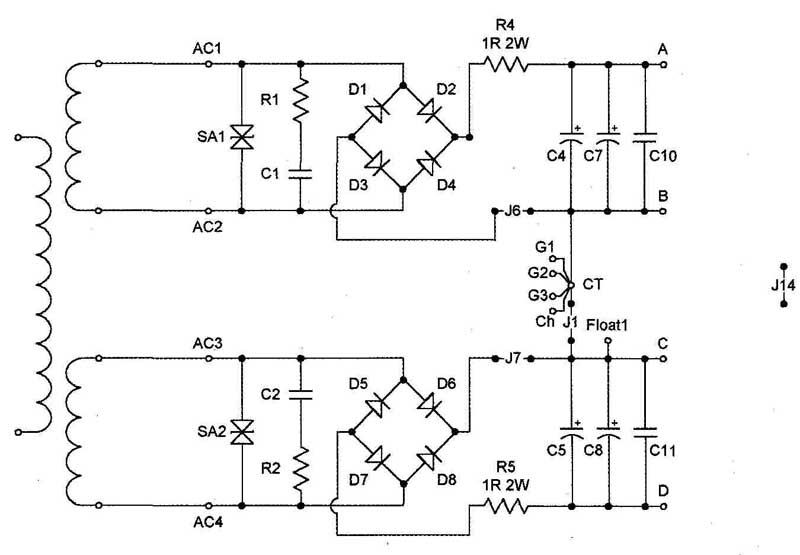 FIGURE 2B: Supplies 1 and 2 input section hookup with separate transformer
secondary windings; these connections are also used with separate transformers.
Note use of J14.
3. Separate supplies for filament voltages, also with separate windings or transformers (Fig. 2C). In this case, leave out 3 to float Supply 2, leave out 31 and connect the Float1 terminal to the floating terminal on the plate supply (there’s one on the Gamp board, or you can make one with a couple of resistors -- see the Gamp article for details). Note that Supply 2 uses a negative regulator; in a filament sup ply this shouldn’t make any difference.
Supply 3’s ground is normally tied to the main power supply ground via J15; however, you could choose to float that one as well for another filament supply by omitting J15 and tying Float2 to a float point. Figure 3 shows suggested wiring for the transformer primary/primaries.
FIRST STAGE
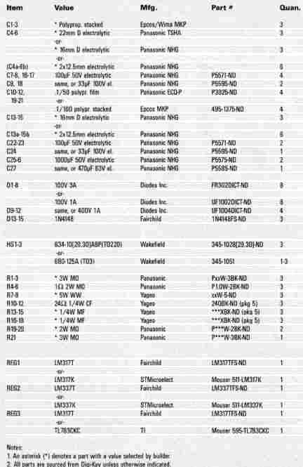
Calculate snubber values using Hagerman’s article. C1-3 should be stacked film caps (Panasonic V series or equivalent); I’ve left room on the board for values up to 0.82uF/50V, or 0.1uF/100V. Use 2W carbon comp resistors if possible, but 3W metal oxide resistors will work in a pinch. The surge absorbers are standard Panasonic ZNR or equivalent; choose a device with an AC clamping voltage 30% higher than the transformer’s nominal secondary voltage.
As specified in the parts list, I chose diodes with fast turn-off times to minimize noise generation. On the board, I left space for either 1A or 3A diodes; if you use 1A diodes, the holes may be a bit loose. Use spacers to lift the diodes about 3/8” above the board surface to allow air to circulate around them, and to prevent their heat from cooking the board.
R4-6 are anti-resonant resistors, as suggested by Ben Duncan. He uses multiple paralleled 1Q resistors; I use just one. These should be 2W, metal oxide or carbon composition.
The capacitor tests I did a few years ago persuaded me that multiple smaller capacitors are more effective than single large ones for filtering out high- frequency junk, either line- or diode sourced The first version of this board had six caps for each section—three big electrolytics, a 100uF electrolytic, a film cap, and a ceramic disc. That’s a pile o’ capacitors, buddy.
Sanity prevailed, however, and I trimmed the count to one or two big electrolytics, one small electrolytic, and a film cap. What sort of capacitors?
For the big electrolytics in the first stage, I made space on the board for three possibilities. In each section there’s room for a 16mm (diameter) wire-lead cap, a 22mm snap-in cap, or two 12.5mm wire-lead caps. (Probably the latter will provide the best performance for a given value of capacitance.) These packages are all bog-standard in diameter and lead-spacing, and available from Panasonic, Nichicon, and others. For wire-lead caps, I prefer the Panasonic NHG series, which have the least inductance for a given capacitance (and thus remain capacitative to a higher frequency). The small electrolytic is 8mm in diameter, typically 100p F/50V for Supplies 1 and 2, and again I like the Panasonic NHG series.
Configuration Jumpers Diodes Transformer connections Output ground
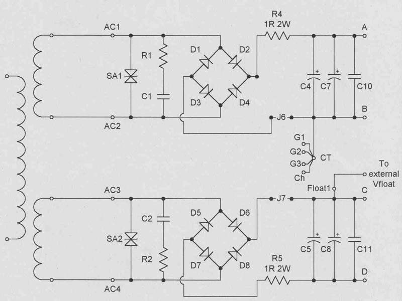
FIGURE 2C: Supplies 1 and 2 input section hookup with Supply 2 floating.
Note that this requires separate transformer secondary windings or separate
transformers, and that J1 and J14 are omitted. The external float voltage
can be up to +75V DC.
What about the film caps? They’re metallized polypropylene with a maximum size of 16.5 x 7.2mm, and lead spacing 10mm. I added pads for 5mm and 7.5mm lead spacing for Wima or Epcos stacked-film capacitors. I’d typically use a Panasonic 0.1uF ECQ-P series or 0.1uF/160V Epcos MKP series cap.
RESISTANCE IS NOT FUTILE
In many ways the dropping resistors between the two filter stages are the heart of this design. They drop the raw voltage to a level that’s appropriate for the regulator inputs, absorb some of the voltage drop of a too-high transformer (taking the heat instead of the regulators), and provide the R for RC filtering. I’ll talk about calculating the resistor values when I do some worked examples in Pt. 2.
There’s room on the board for sand- cast 5W resistors; for lower-power circuits, you can use 2W carbon comp or metal oxide resistors, but figure out the worst-case dissipation on the case before choosing, and be conservative.
IF IT MOVES, REGULATE IT
The default regulators are LM317T for the two positive supplies and LM337T for the negative. These are TO-220 packages, readily available, and mount on Wakefield 637-series heatsinks. (The heatsinks come in four heights, for different power levels.) These handle low-voltage, low-current loads just fine—but they’re not the only possibilities.
What if you need higher voltages— for example, +48V from Supply 3 for phantom-powered microphones? In that case, you can use a Texas Instruments TL783CKC regulator, which is pin-compatible with the LM317T and uses similar design procedures, although with slightly different numbers.
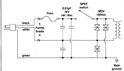
FIGURE 3: Suggested wiring of primary circuit, size fuse as needed. In a
240v system, use a 300V MOV.
Notes:
1. An asterisk (*) denotes a part with a value selected by builder
2. All parts are sourced from Digi-Key unless otherwise indicated.
Higher-current circuits such as tube filaments may draw more current than the TO-220 package can safely dissipate. Happily, you can still get LM317K and LM337K devices; these are TO-3 pack ages and (when mounted off-board on suitable heatsinks) can dissipate more power. I’ve put pads on the boards for connecting to off-board regulators.
Finally, LT1085/1033 regulators, designed for higher currents, also provide somewhat better regulation and line rejection; choose these if you want the board to provide higher audio performance. They cost a lot more, though. (There’s probably no advantage to higher-end regulators if you’re using the Tri-Way as a pre-regulator).
My regulator circuits are pretty much textbook designs, with a couple of exceptions. The application notes for regulators suggest that, when you use them with large output capacitors, you should connect a protection diode between the input and output terminals (D13-15 in this circuit). This lets the output cap discharge through the diode while clamping output-input voltage, which keeps the regulator from frying.
Unfortunately, the lN400x diodes recommended for this application have high capacitance, which can conduct high-frequency crud from the regulator’s input to the output and thence into your audio circuits. Ben Duncan suggests using 1N4148 or 1N914 diodes instead; these have lower capacitance and thus provide a better barrier. They’re lower-power devices, though; to keep them from frying themselves, you need a small series resistor to limit the current during discharge (R10-12).
There are also three load resistors (R19-21). I’ll talk about those in the final worked example (most of the time, you won’t need them). The regulator circuits include bypass capacitors (C22-24) between the adjust terminals and ground. These improve performance on LM317/337 regulators, and LM1085/1033s as well. Texas Instruments, however, recommends not using them on the TL783, so you should leave them off if you use that chip.
VARIATIONS ON A GROUND
These days, most audio designs use a strict star ground; everything (audio circuits, power supplies, chassis) is returned to a single grounding point. I’ve found, however, that there’s one exception: the “ground” reference point on regulators should be connected to the load’s ground point, with the latter connected to main system ground. This is easy to do on the Tri-Way board, since the regulator reference points have their own output connection points.
MECHANICAL CONSIDERATIONS
I’ve drilled all input and output pads with 0.042” holes, which can hold a wide variety of standard terminals. In an experimental or hobbyist setup, it’s often worthwhile using terminals rather than soldering wires directly to the pads; if you wind up desoldering and resoldering, terminals make it much less likely that you’ll lift traces on the board. Even if you don’t desolder, repeated flexing of wires as you troubleshoot a project can put mechanical stress on solder joints and pads.
The board has a line across it, between the diode/first filter section and the second filter section/regulator. If you like, you can saw the board in half and place the first piece in an external box while the regulator piece goes into the main chassis, or mount the two halves vertically in a 2U rack chassis.
I’ve placed holes, suitable for 4-40 screws, in the four corners of the board sections. While I’ve tried to keep these away from live circuit traces, it’s still a good idea to avoid shorts by using nylon standoffs rather than metal. The holes can also be used for right-angle brackets; again, watch out for shorts!
Finally, I’ve designed the Tri-Way so that the cathodes (striped ends) of all diodes and the + terminals of all electrolytic capacitors are on the right, as you look at the component side. Nothing is idiot-proof (I’ve pulled my share of dumb moves), but this helps avoid assembly errors that cause loud bangs.
Next in Part 2 (coming soon!!), we put this board through its paces, showing three different designs using the Tri Way. Meanwhile, go ahead build the Tri-Way. This article is all you need to build and use this handy device!
REFERENCES
1. Paul J. Stamler, “The Camp,” July ‘07 audioXpress , p. 20.
2. Paul J. Stamler “In Praise of Wall Warts,” Jan.’08 audioXpress , p.2
3. Walt Jung, “Regulators for High-Performance Audio, Part 2,” 2/95 Audio Amateur, p. 20.
4. Michael Sulzer, “A High Quality Power Supply Regulator for Operational Amplifier Preamplifiers,” 2/80 Audio Amateur, p. 8.
5. Walt Jung, “Regulators for High-Performance Audio, Part 1,” 1/95 Audio Amateur, p. 8.
6. Paul J. Stamler, “Mixers and Mike Pre amps, Part 2,” 4/95 Audio Amateur, p. 18.
7. Ben Duncan, “A State-of-the-Art Preamp: AMP 02,” Hi-Fi News & Record Review 34:11 (November 1989), p. 45.
8. Jim Hagerman, “Calculating Optimum Snubbers,” 1/98 Audio Electronics.
9. Paul J. Stamler, “Capacitor Bypass: Proceed Carefully,” May’05 audioXpress .
