SAVE THE TUBES: Here are some tips
from a tube veteran on how to extend the life of your tubes.
--------------
Class A audio is among the least stressful uses for a tube if you take precautions to avoid conditions known to lead to premature failures. This article shows you how.
By Larry Lisle
Vacuum tubes have an undeserved reputation as being short-lived, unreliable devices.
They're not. When operated with care, tubes can last thousands of hours.
RECONDITIONING NOS TUBES
Many tubes used today are 40, 50, or more years old! Even though they're NOS (new, old stock) they've been sit ting a long time, and you should take some precautions before firing them up, especially the big costly ones! First, hold the tube upright and gently tap the envelope to let tiny particles of whatever may have been left inside the envelope settle to the bottom be fore they cause arcing. Next, reactivate the getter to remove any gas that may have invaded the tube through the seals during its decades on the shelf.
The easiest way to do this is to build a simple test stand with an appropriate socket (Fig. 1).
Wire the filament pins to a source of the correct voltage; the grid should be connected to the cathode through a 1k ohm resistor; the plate and screen are tied together and connected to a source of 200V or so through a milliammeter.
The cathode is connected to ground through a variable resistor of a value and wattage that will limit the current to about one-third of normal. (Consult a tube manual and use Ohm's law.) Apply the filament voltage gradually, and then apply the B+, also gradually, watching the milliammeter for signs of runaway.
If all seems well, let the tube idle for a few hours, and it should be ready.
PHYSICAL CONSIDERATIONS
Putting a tube, especially one in which the pins go directly through the glass envelope, into a socket can be very hard on the tube. It's easy to start a crack that may eventually lead to tube failure. Be careful in removing and replacing tubes. I recommend a pin straightener.
Remember, sockets should have some "give" around the pins. Be careful when soldering that each of the socket holes has a little wiggle room.
Filamentary tubes should be oriented properly so the filament doesn't sag near another element-vertical is best. Some times manufacturers will say horizontal mounting is permitted if certain socket pins are in a vertical plane. This is true if the elements are in alignment with those pins. Sometimes they're a little off, and a rectifier, for instance, working at near maximum ratings may arc when it wouldn't normally be expected to.
Be cautious, also, about working with filamentary tubes on a chassis tipped on its side for servicing or testing. It's better to turn it completely up side down.
Any metal that comes in contact with the glass envelope of a tube can cause the glass to heat or cool unevenly, which may eventually lead to failure.
Speaking of heat, this is probably the worst enemy of tubes and other components. Don't crowd your chassis; allow for ventilation. Tube coolers and forced air cooling may be worth looking at.
Use shields only when absolutely necessary, and then use only those with blackened interiors.
CIRCUIT CONSIDERATIONS
Filament voltages in excess of the center value given in the manuals should be avoided. It's far better to let the filaments run a few percent low than too high. Also, try to limit the strains caused by turning on filaments. Possible methods include letting the filaments run all the time, even when the high voltage and bias are turned off, or letting them run at 50% voltage when the other voltages are turned off. These methods are more suitable for studios.
For the home, use a surge-protection system, which can be as simple as a resistor and a switch.
Never apply the plate or screen volt age until the cathode is at operating temperature.
(Tube manuals usually list filament heating times.-Ed.)
Try to avoid having more than 90V between the filament and cathode, no matter what the manual says.
Fixed grid or screen voltages can lead to tube failure in the event of the demise of another component, but sonic considerations may conflict with this. If there's a choice between two tubes to do the same job, other things being equal, the one with the bigger elements and envelope will probably last longer.
200V DC MILLIAMMETER AC IN 1K
SEE TEXT FILAMENT TRANSFORMER VARIAC
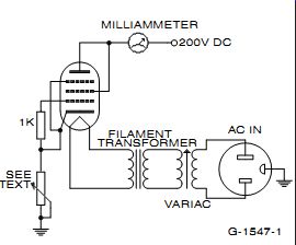
FIGURE 1: Schematic of a simple test stand.
-----------
ABOUT THE AUTHOR: Larry Lisle is a teacher in Rockford, Ill. He has been writing articles, generally of a technical nature, since 1968. His hobbies include building and restoring audio and radio equipment, amateur radio, and coaching basketball.
-----------
Be careful to avoid unwittingly using a "select" tube in a circuit you're designing. That is, if at all possible, try several tubes of the same type in the socket of your prototype to make sure it works satisfactorily with all of them. If you design your circuit around one tube and it happens to have unusually high transconductance or low micro phonics or hum or whatever, you may have difficulty in the future understanding why your circuit stopped working correctly and a new tube won't fix it.
If your design includes filamentary and heater-type tubes, take into consideration the different warm-up rates and be sure all tubes are properly biased when the high voltage is applied.
Finally, check your line voltage from time to time. Some areas frequently run much higher than the standard 117V.
This can shorten tube and component life. Also, remember that many years ago the standard was 110V. If you're running some antique equipment, you could really be over voltage! TUBE TESTING I'm not very fond of tube testers for two reasons: first, they usually don't test the tubes under the conditions of the circuit they're used in (an exception is the simple tester I described in "An Audio Tube Tester," GA 1/98, p. 12).
The second reason is that they can actually harm the tube they're testing. For example, some testers connect all the elements except the filament and cathode together and apply AC voltage through a milliammeter between the cathode and the other elements. The idea is to test the emission of the cathode. But the grid is now many volts positive compared to the cathode, and in high-transconductance types it can easily draw excessive current and be overheated. I much prefer to "test" a suspect tube by replacing it with a known good one.
For routine checks on tubes, as in a studio, include in the circuitry a provision for easily measuring the plate cur rent of each tube in an amplifier while the circuit is functioning normally. This will be more enlightening than a tube tester reading, and will avoid the need to remove and replace tubes in their sockets, which can lead to eventual failure. It will also tell much about how the whole stage is doing, not just the tube.
I hope some of this material will prove useful. It's fortunate that some tubes continue to be made and some excellent new types have been introduced. Other less popular tubes are definitely a nonrenewable resource, but with care they can last a long, long time.
FURTHER READING:
Tomer, Robert, Getting The Most Out of Vacuum Tubes, Howard Sams, 1960. An excellent book on tube reliability, hard to find. (The book is available from Old Colony.) Smith, Langford, Radiotron Designers Handbook, 4th Ed., Part 1. Available from Old Colony Sound Lab, 888 924-9465, audioXpress.com.
Kleronomos, Bill, "Don't be Sorry! Condition Those Tubes," Electric Radio Magazine, Nov. 1993, Electric Radio Press Inc., 14643 Counth Rd. G, Cortez, CO 81321-9575. Excellent article on de-gassing old tubes.
Kleronomos, Bill, "Electron Tube Survival Primer," Electric Radio Magazine, Oct. 1994. Tube shields com pared.
Osterwald, Ray, "Thermionic Mysteries," Electric Radio Magazine, Oct. 1993. A look at cathode interface resistance.
--------------
Also see:
A QUICK BOOKSHELF PAIR: This author finds a way to satisfy his audio needs with a basic 5” driver-in a-box design.