By G. R. Koonce
Some concluding tips on how to achieve success in your own designs.
CALCULATION OF FRONT PANEL TIP ANGLE
Figure 46 shows the conditions for a floor-standing enclosure with a tipped front panel. All positive angles are shown and exaggerated in this figure for clarity. The front-panel tip angle (FPta) is the angle that the front panel is tipped back from vertical. Tipping the front panel rotates the tweeter's zero degree line an amount equal to the FPta. A positive VBA rotates the "line" to the listener upward even more. The object is to pick a FPta that aims the VBA at the seated listener.
Figure 47 offers a plot to help accomplish this. On the horizontal axis locate the height the tweeter will be above the floor (TH) in the enclosure. Go vertical to the line nearest your listening distance (LD). Then horizontal to establish the required seated total angle (TAx), which is the angle from horizontal to the "line" to the listener (Fig. 46).
The FPta is equal to the TAx minus VBA. It is quite possible that FPta will turn out negative, indicating the front panel must tip forward at the top. I have never built a cabinet like this and suggest you develop some alternate approach. Lowering the tweeter in the box surely would help.
Consider an example using the Sys119 developed earlier. This 8 ” woofer with 1 ” dome tweeter showed a VBA of -8°. With a pedestal under the box to mount the CO, the tweeter is going to be about 14 ” off the floor.
Start at 14 ” on the horizontal axis of Fig. 47 and move vertical to, say, 8' listening distance (LD). Then, move horizontal to get TAx = 14°. This means FPta = 14 - (-8) =+22°, which is an excessive angle to tip back a front panel covered with heavy drivers. I normally limit the tip angle for boxes with a vertical array of drivers to 15°.
Now examine Sys119 for the possibility of building with the woofer above the tweeter. This means the VBA is now +8° and the tweeter height is about 6 ” off the floor. Using Fig. 47, this results in a TAx of 18° and a FPta of (18 - 8) or +10°. Constructed with the woofer at the top, Sys119 sounded just fine.
CHANGE IN LISTENING ANGLE FOR STANDING LISTENER
If you optimize the design for the seated listener, you also need to have some idea of what happens for the standing listener. Figure 48 solves this--both for the box on a stand and the floor-standing box.
Identify the tweeter height from the floor (TH). Locate this value on the horizontal axis and move vertically to the closest listening distance (LD) line and then horizontally to the change in beam angle, which to the standing listener is the VBA plus this change. Since the standing listener is taller than the seated listener, the change in angle is al ways positive.
For example, first, consider the BT2W system as used on tall stands with the tweeter above the woofer for a LD of 10'. The tweeter height turned out to be 46 ” for the system VBA of -4°. Figure 48 yields a change in beam angle of +13°, meaning the standing listener will listen to the system at +9°. The system vertical polar plot (Fig. 21 in Part 3) and the vertical directivity plot (Fig. 22 in Part 3) show the vertical response is just starting to deteriorate by +10°.
Suppose you built BT2W with the tweeter at the bottom, and the tweeter height for 10' listening was 30 ” and the VBA =+4°. Using Fig. 48 yields a change in beam angle of +13°. So the standing listener vertical angle is +17°.
Now because you have inverted the angles by putting the woofer at the top, you need to look at the polar and directivity plots at -17°. This system holds up much better for negative angles, so building with the woofer at the top and using lower stands looks like the better option.
With Sys119 the only real option was building with the woofer at the top, which gave a tweeter height of 6 ” and a VBA of +8° with a listening distance of 8'. From Fig. 48 you get a change in vertical angle of +13°. This adds to the VBA, giving +21° as the standing beam angle. Again, because you have inverted the system, you must look at the polar plot (Fig. 30 in Part 3) and directivity plot (Fig. 31 in Part 3) at -21°. This system holds up much better at negative angles than positive, so once again building with the inverted configuration looks good.
If you are especially interested in a system that is flat for the standing listener, you can compromise by aiming the VBA slightly above the seated listener's ears. This compromises the seated listener's response slightly to give a more consistent response between seated and standing listening. You can accomplish this by designing with a very high seated listener ear height, perhaps using the average of the seated and standing ear height.
SIMPLE WAYS TO BUILD WITH TIPPED FRONT PANELS
This section shows some of the methods I have used over the years to con struct boxes that have a tipped front panel and are relatively easy to build.
Figure 49 shows the simplest construction I know for building an enclosure with a tipped front panel (FP). The basic internal box is rectangular, while the sides are extended down and cut off at an angle. While not recommended for large enclosures, this simple approach has several neat features.
You can determine the angle on the side boards and cut it at the last minute or even possibly re-cut it on the finished box. You can fill the gap below the bottom board at the front with a "fill strip," which is the only piece you need to cut at a blade angle other than 90°.
The pedestal formed below the box is an ideal place to mount the CO. Note in Fig. 49 the FP has been set back to form a grille frame. You could make the FP flush with the box front and even cut the bottom board short so the FP is full height to avoid the fill strip.
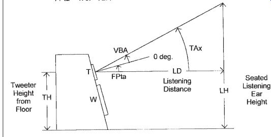
FIGURE 46: Conditions for floor-standing enclosure with tipped front
panel.
Figure 50 shows the classic approach to a tipped FP with a box that has a horizontal top and bottom with a vertical back. Again, you can flush or set back the FP as desired, or even add a pedestal for the CO. This box requires angular cuts (blade not at 90° to the face of the board) on both ends of the FP and one end of the top and bottom, but all cuts are the same angle. Construction is thus reasonably simple.
Figure 51 shows a construction that I have used many times. The top is perpendicular to the back while the bottom is perpendicular to the FP. This box is ideal for a vented-box system using the diffusor port that I like. The port duct is located in the bottom board and dumps into the triangular area formed by the floor and bottom board.
13,14
This construction also has the advantage that the sides are the only parallel opposing panels. Again, you can flush or set back the FP to form a grille frame, and add a fill strip at the front, below the bottom board, to allow the pedestal to house the CO. One problem is designing this structure to a given volume. It is simple to compute the volume of a defined box, but difficult to determine the required depth or height for a desired volume.
Once again I mention the approach used by David Weems, which is to build a rectangular box and set it on a very low stand that sets the FP tip angle by tipping the entire box. Remember this will slightly change the tweeter height and may require recalculation of the desired tip angle, but this approach does offer the advantage of building such stands after you have experimented with listening to the boxes at various tip angles set by convenient shims at the front. If you use the speakers in different locations with a large difference in listening distance, you could build different stands suitable for each location.
SUMMARY
Is there any way to know the location of the vertical beam angle for your system without modeling or testing capability? Certain configurations are predictable,
but in general I believe the answer is no. I have reviewed a reasonable number of systems using second-order electrical COs, and the VBA varied from about -10° to +15°. Tweeter wiring polarity did not predict whether the VBA would be positive or negative. The following are the only ways I know to determine the vertical beam angle with out testing or modeling:
1. Go with a developed design having a known vertical beam angle.
2. Build with a quality coaxial type driver that will have a VBA near zero degrees.
3. Build with the D'Appolito symmetrical W-T-W configuration where the symmetry will force a zero degree VBA about the tweeter. The usable width of the main vertical lobe may still be an unknown that could affect the standing listening. This configuration is developed in reference 15.
4. Build the upper end of the system -- i.e., the region above the subwoofer-- with a single driver per satellite. The satellite will have a zero degree VBA about the center of that driver. The low-frequency CO to the subwoofer does not have the same type of problems we have been discussing, be cause the wavelengths are so long.
Note that the development of a three way system can be even more difficult.
You need to develop CO networks so that the VBA for both CO frequencies work together. The lower the CO frequency, generally the wider the vertical lobe, so you need to work for a usable VBA for the upper CO that fits well in the wide vertical lobe of the lower CO frequency. Here the vertical directivity plot shows whether you have accomplished this much quicker than trying to compare vertical polar plots about the two CO frequencies.
There is little doubt that flush-mounting tweeters reduces the edge diffraction that occurs at the edge of the faceplate.
Flush-mounting the woofer may also help the tweeter's response, but testing has shown not as much as you would expect, because even a flush-mounted woofer does not show a "flat" front panel to the tweeter's response. You must keep in mind that such flush-mounting changes the relationship of the acoustic centers for the drivers, and this must be factored into the CO design.
Moving a midrange or tweeter off the cabinet centerline is also helpful in spreading out the edge diffraction that occurs at the cabinet edges. An offset of an inch or so is not a problem, but large offsets are harmful to the horizontal directivity.
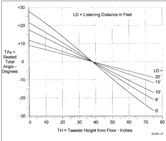
FIGURE 47: Plot to allow establishing seated total angle for a floor-standing
enclosure with tipped front panel.
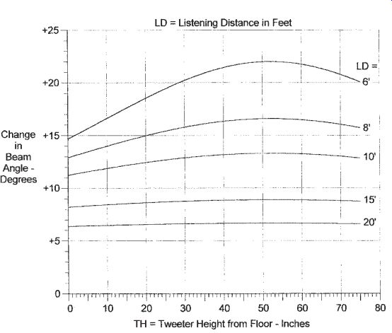
FIG. 48: Plot of change in beam angle versus tweeter height.
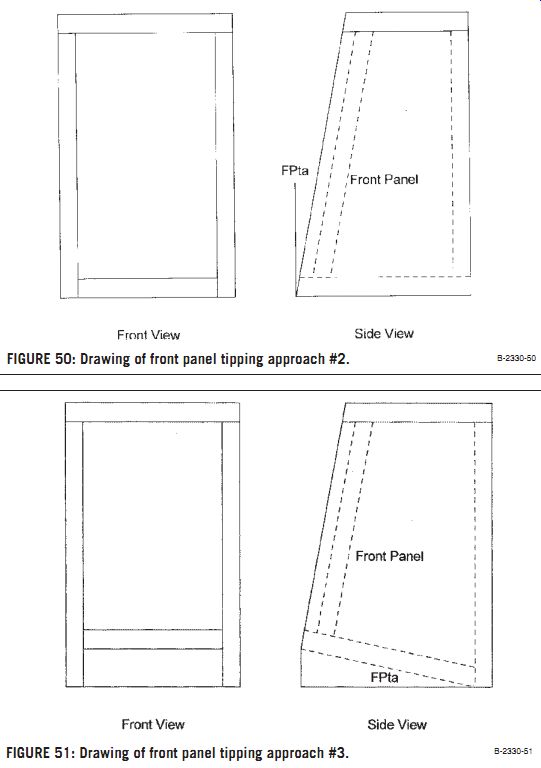
FIG. 50: Drawing of front panel tipping approach #2. FIG. 51: Drawing
of front panel tipping approach #3.
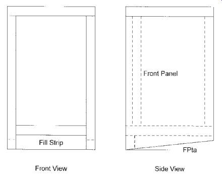
FIG. 49: Drawing of front panel tipping approach #1.
This article totally ignores the problem of diffraction spreading loss, which causes the on-axis bass response to fall below a certain frequency based on the size of the enclosure.
This problem occurs in enclosures that set out from the walls. It is not as severe for floor-standing boxes with low mounted woofers, but must be considered for tall, thin enclosures with high mounted woofers and boxes setting on stands. It can also be a big problem on tiny satellite enclosures where it can modify the on-axis response up into the midrange frequencies.
Keep in mind all of the work presented here represents modeling or testing in a near-anechoic environment. When using a speaker system in real rooms, not addressed here, you consider all sorts of room effects that come into play. Most of these room effects are most prominent in the bass frequency range, but some may factor into your choice of driver CTC spacing. This sometimes makes your CO design problem even more difficult.
For a listener perceived flat frequency response, it has been demonstrated that the direct or "first arrival" response should have a flat frequency response. For good imaging it is considered important that the frequency response degrades smoothly in the horizontal plane. These are what this work has concentrated on achieving.
EQUATIONS FOR ESTABLISHING STAND HEIGHT OR FRONT PANEL TIP ANGLE
Note: All angles in degrees and all linear dimensions in inches. All angles are taken as positive moving up from horizontal.
VBA = Vertical beam angle-center of system's vertical response lobe.
LH = Seated listener ear height in inches (38" used in plots).
LD = Distance from speaker to listener in inches(plots show LD in feet for convenience).
TH = Height of the tweeter center above the floor in inches.
A. For figuring the stand height for an enclosure with a vertical front panel:
TH = LH - [LD × Tan(VBA)]
The required stand height is one that puts the tweeter center at height = TH.
B. For figuring the front panel tip angle for a floor-standing enclosure:
FPta = The required front panel tip angle in degrees. Positive means the front panel is tipped back into the box at the top.
TAx = Total angle from horizontal up to the line from tweeter center to the seated listener. Above horizontal is taken as positive.
TAx = ArcTan[(LH - TH) / LD] FPta = TAx - VBA C.
To calculate the beam angle for standing listening. Can be used for both stand-mounted and floor-standing boxes.
LHs = Standing listener ear height in inches (plot used 66").
SVBA = Vertical beam angle to standing listener.
SVBA = ArcTan[(LHs - TH) / LD] - ArcTan[(LH - TH) / LD] + VBA
If the front panel is vertical, for either case, this reduces to:
SVBA = ArcTan[(LHs - TH) / LD]
Be careful here if you have "inverted" the system (built with woofer over the tweeter).
This changes the sign of the VBA, and you must remember to change the sign of the SVBA when referring to plots.
REFERENCES
13. Koonce, G. R., "A Diffuser Port for Small Boxes," SB 2/81, p. #16.
14. Koonce, G. R., "The Diffusor Port," Ask Speaker Builder, SB 2/91, p. #45.
15. D'Appolito, Joseph, "A High-Power Satellite Speaker," SB 4/84, p. #7.
------------------
Also see: VIRTOS NOISE WIZARD