|
|
.If you’re tired of the noise and distortion of resistors and capacitors in the signal path, try the minimalist approach to amplifier design and experience something new!
From the beginning of electronic audio reproduction, the major design trends have been to achieve wider bandwidth, lower distortion, and greater power. An unwanted byproduct has usually been more complicated equipment with more and more parts. Unfortunately, each part can add its own coloration to the sound. It may not be readily measurable but it is perceivable, especially in a long listening session.
The minimalist approach goes in the opposite direction. What can be done with the fewest components possible? One result has been an amplifier with three parts: an input transformer, a tube, and an output transformer.
The circuit (Fig. 1) is really from the 1920s, but they didn’t have the music sources, the transformers, or the speakers to hear what it could do. With top-quality components, this amplifier is nearly flat from 20Hz to 20kHz, has low distortion, will provide a good listening level with sensitive speakers or ear phones, is extremely quiet, and sounds absolutely gorgeous!
QUALITY, NOT QUANTITY
Few parts, however, does not mean cheap. You must use the highest quality parts in a minimalist design. There is no other circuitry to compensate; you must get the sound right the first time! The power supplies for the plate, grid, and filament also must be top quality.
This is not really a straightforward construction article because the parts used in the amplifier (Photo 1) haven’t been made for many years. But you can find them—or near equivalents from the golden age—-if you look hard enough. There are also modern manufactured substitutes that sound very nice. Remember: for stereo, you will need two of everything for the amplifiers. Also, I recommend two completely separate power supplies.
The amplifier shown is designed to take its input from the headphone jack of a CD player. The signal is fed into what is called an “input transformer” of the type used to match a dynamic microphone, voice coil, or line to a grid. The impedance of the input winding should approximately match that of the output of the CD player while the secondary for the grid is in the 40,000 to 80,000 ohm range.
If you don’t know the impedance of your player, you can try a value of about 50—150 ohm, or you can find the exact value by the following procedure:
Play a CD with a steady sine-wave tone and measure the open circuit voltage. Then place a variable resistor across the output. The value of resistance that reduces the output by half is the output impedance.
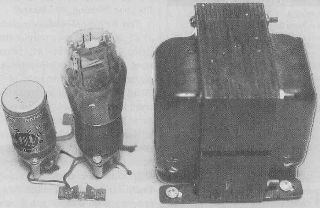
PHOTO 1: a “minimalist” amplifier with only three parts. There are no resistors
dr capacitors in the signal path only two excellent transformers and a great
tube. It’s like opening a door to the music.
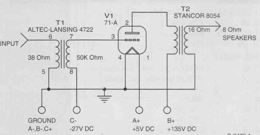
FIGURE 1: the circuit of the minimalist amplifier as shown in the photo. Its
a simple circuit, but its not cheap! See the t for details
By the way, many older input transformers were designed for speech only and emphasize the frequencies below 3kHz. You definitely don’t want one of these for music. Before you pay big bucks for a transformer, be sure you know what you’re getting!
PARTS SELECTION
Of the many transformers I auditioned for this article, my favorites were the Altec-Lansing Peerless transformers and those from United Transformer Company (UT). Among modem manufacturers, I like the Hammond 806 and 808—which are available on special order from sup pliers of Hammond products—and those from Electra-Print; the latter being custom-made to your specifications. Remember to stay below the maximum power level of the transformer. Amplifier performance with sample transformers is shown in fig. 2.
For example, the Hammond 808 is rated at +15dBm. This means that in the 50-ohm input configuration the input voltage should be less than 1.257V. See the Radiotron Designer’s Handbook, Chapter 5, Section 3 (iii) (b) for more information on input trans formers. The key differences in input transformers—separating the best from the good—are bandwidth in the circuit you’re using and the production of odd harmonics in the transformer.
The tube I chose is the 71-A. I used to think nothing could beat a single-ended 45. I was wrong. A minimalist amplifier really shows what this beautiful tube can do. The 71-A (or older 171-A) is about the largest tube that you can, as a practical matter, light its filament with batteries.
Remember that I said a minimalist amplifier wasn’t cheap! I use four alkaline 13 cells and a 2512 variable resistor (Fig. 3). When the voltage drops below 5V with the resistor at minimum, I switch in a fifth battery. This scheme gives remarkably long life. You could, of course, use rechargeable batteries. You could use a conventional line-voltage-operated power supply, but it may not sound the same. Try batteries first.
OPERATION
As long as we’re talking about power supplies, the high voltage of 135V is supplied by a transformer and a conventional 5U4 tube rectifier in a full-wave circuit (Photo 3). A separate transformer supplies 5V for the filament of the 5U4 and the positive voltage is taken from the center tap of the filament winding. The voltage then goes to a 2k12 vari able resistor to adjust the output to precisely 135V.
I did this to audition different parts under identical conditions in spite of changes in the line voltage. In usual practice you could replace the variable with a fixed resistor, which also serves to limit the sudden rush of current when the power supply is first turned on. This isn’t really necessary as the 5U4 just loafs in this circuit.
Filtering is done by an electrolytic capacitor, a choke, an electrolytic capacitor, a choke, and paralleled 10 and 30uF oil-filled output capacitors. (Only the 10uF is shown connected in the photo.) Oil caps are big! I like the sound of an oil-filled capacitor in this position because it also serves as a plate return for the amplifier. A bleeder resistor is located across the output capacitor.
Be careful of all capacitors. Make sure they are discharged before touching anything on the power supply or amplifier alter unplugging from the AC outlet. Oil-filled capacitors especially can hold a charge for a long time. Don’t trust the bleeder resistor. Discharge the capacitors manually.
Bias voltage is supplied by three 9V transistor batteries in series. The output transformer is a Stancor 8054 from the 1950s. This is a push-pull transformer, but with the plate current of only about 14mA it shows no sign of saturation. It’s one of the best-sounding transformers I have. The primary is 9k-ohm, and I connect an 8-ohm speaker load to the 16-ohm tap of the secondary. This gives a load of 4500-ohm and uses the entire secondary winding.
There are many single-ended output transformers on the market today, so finding something suitable shouldn’t be a problem. If you happen to have a very high quality push-pull transformer though, give it a try. At low plate current many classics will actually sound and measure better than transformers designed for single-ended use.
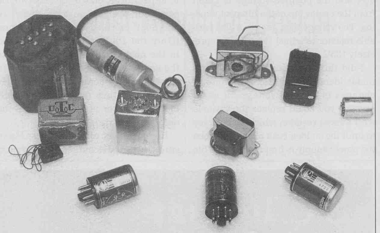
PHOTO 2: a variety of input transformers by utc, hammond, electra-print, and
altec-lansing.
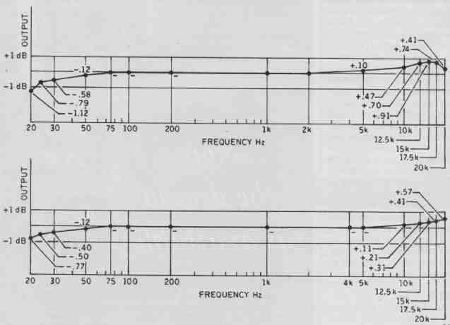
PHOTO 2: with good transformers -- almost flat!
Construction of the amplifier, the B supply and the A and C battery supplies (not shown in the photos) is on pieces of poplar 11½ x 7¼” (actual measure). Assemble these in a wooden cabinet. (Call it 1920s surface mount.) I did this for sonic reasons, as I’ve found there are fewer problems with unwanted couplings using wood than with metal. If the transformers you’re using aren’t shielded properly, you may need to reconsider this point. Wires carrying A, B, and C voltages to the amplifier should be shielded and their shields connected to the amplifier’s common ground point. Power supplies with AC inputs should not be located dose to the amplifier.
CRITIQUE
So how does it sound? Calling this amplifier “musical” is like calling Napoleon a soldier. It is a joy to listen to—it’s like opening a door. It is extremely ac curate. What goes in is what comes out, but louder. It’s very close to the mythical “straight wire with gain” and a taste of single-ended goodness thrown in.
One of the most telling evaluations of an amplifier is how well it reproduces the human voice. We’ve had our brains wired since infancy to recognize voices and we’re good at it. Few amps give the experience of a listener jerking his/her head around toward the speaker to see who is there. This amplifier does. It makes it seem real.
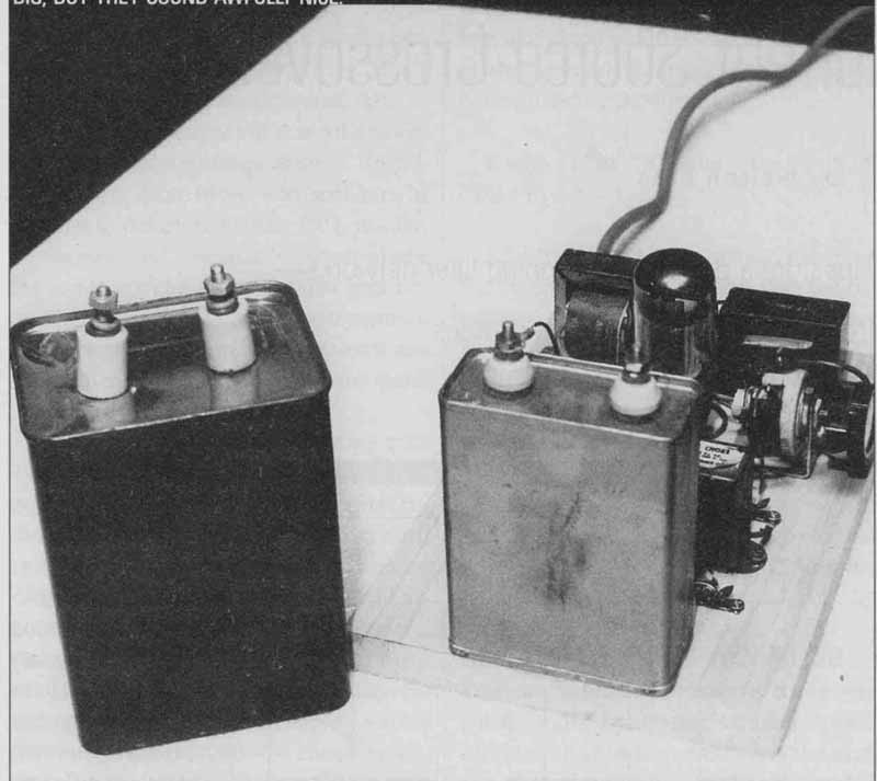
PHOTO 3: The high voltage, or “b” power supply uses a 5u4 in a full-wave circuit
with plenty of filtering. Parallel 1ouf and 3orf oil-filled capacitors are
used at the output, which also serves as the plate return circuit of the amplifier.
Oil caps are big, but they sound awfully nice.
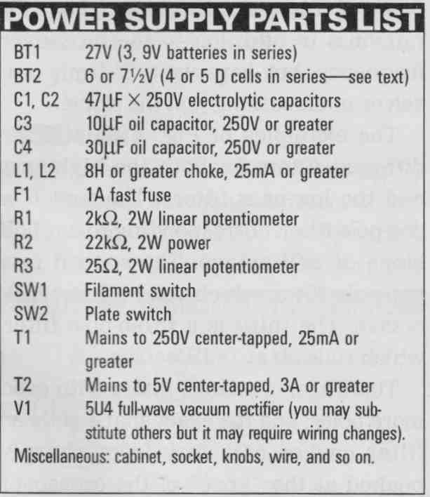
---PARTS LIST: Miscellaneous: cabinet, socket, knobs, wire, and so on.
Sinatra on his best recordings is unbelievable. So is Ella Fitzgerald. The separation of instruments on Buddy Rich’s “Big Swing Face” is outstanding. I’m hearing things on familiar recordings that I never noticed before. I’m also hearing deficiencies on some CDs that I had overlooked.
I didn’t expect it to have much bass until I put on Bill Doggett’s “All His Hits” or recordings by Sonny Burgess (maybe the best of the rockabilly artists), who knows what drums are for. Of course, it won’t ripple the carpet, but it will reproduce what’s on the CD at a comfortable listening level with sensitive speakers—no bricks with binding posts, please. It is a truly wonderful little amplifier.
= = = =