|
|
Having refined my stereo system to a pleasing level of fidelity, and with a Blu-ray player that sends out 7.1 channels of analog sound, I decided it was time for some surround speakers. Learning of this, my friend Jason brought his mini-monitor Vanishing Loudspeakers over one weekend and gave me a convincing demonstration using Blu-ray movies. The best experience was the aural sensation of James Bond racing an Aston Martin DBS, accompanied by a snarling engine, screeching tires, and gunfire.
That decided it--I would build a pair of THX surround speakers (shown above).
My design approach for the new surrounds was to make them a modernized version of the Vanishing Loudspeakers, giving structural issues added attention, and, of course, meeting the THX standard for surrounds. I would also build stands that were not adaptations, and impose my own choices on their features.
I would rely on Vic's collection of measurement, modeling, and crossover design software for the crossover part of the project. The cabinet design, driver impedance measurement, modeling, and all construction fell to me.
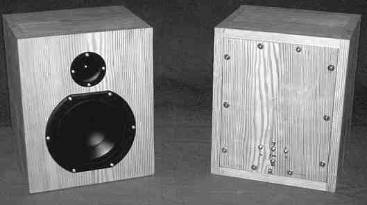
ABOVE: PHOTO 1: Cabinet front and rear view.
DRIVERS USED:
Jason researched the descendants of his original drivers and chose the Peerless 830874 for the woofer and Peerless BC 25SC06-04 for the tweeter. The woofer is a 6.5” polypropylene cone driver, while the tweeter has a 1” fabric dome with ferrofluid damping. Detailed specifications are available on the web (tymphany.com). I ordered three woofers and five tweeters in case anything should go wrong; however the spares are still unused at the time of this writing.
CABINET VOLUME:
The THX specification for surround speaker frequency response is 80Hz and up, making sealed-box volume computation straightforward. I increased the theoretical volume of 548 in3 by 20% to allow for driver components and internal bracing, but no crossovers. Applying the "ideal" proportions of 0.8 × 1.0 × 1.25, I rounded up the box internal dimensions slightly to 8.75W × 10.875H × 7.0” D.
CABINET MATERIAL:
Aiming to improve upon past boxes made from MDF particleboard, I studied wood species in Table 4-3b of Reference 3. I rated potential candidates based on the ratio of Modulus of Elasticity (the higher, the stiffer) divided by Specific Gravity (the lower, the lighter).
Next, I visited the best lumberyard in the area to size up the winning Coastal Douglas Fir, which they had in abundance. I purchased two pieces of 1 × 6 × 14 S4S, which measures ¾” × 5½” × 14” , surfaced four sides. That gave me stock for two cabinets, and I intended to edge-splice boards for all surfaces (this improves appearance and reduces any tendency to warp).
I exploited the relative stiffness of this wood to resist deflections, and to have the lower mass store less vibrational energy and be damped quicker by the final choice of deadener.
A practical word of advice: This species of wood is very prone to splitting due to its pronounced grain, and makes painful splinters. All saws, drills, router bits, and so on must be as sharp as possible for clean cuts. More exotic woods in Ref. 3 are candidates, so you can make other choices.
CABINET STRUCTURE:
Small home-built speaker cabinets are great subjects for sophisticated construction, because very little more time and materials are needed to achieve truly high-end results.
The tweeter is mounted just above the woofer, but with enough front panel wood left between their cutouts to attach the sturdy cross-brace glued to the back side of the front panel. That cross-brace is made of a T-section with holes cut out of the web to minimize reflected sound bouncing back out through the woofer.
The rear panel is removable (Photo 2).
Internal bracing is applied to all four front-to-back panels to improve their rigidity. This method, which has appeared in several articles, works wonders.
ASSEMBLY:
My choice of glue in building the cabinets was yellow aliphatic carpenter's glue, clamped or weighted during assembly, using no fasteners.
Figure 1 shows the cabinet design, while Photo 2 gives a better idea where the bracing is applied to stiffen the panels.
The internal T-section bracing, made from strips ripped from the edges of leftover ¾” fir, is located about one-third of the way into the box from the rear.
The cross-braces are attached with small shear plates visible in Photo 2.
After assembling all the components, I used a belt sander to even up the external joints and develop a uniformly smooth surface. This wood is a plea sure to work with and is pleasantly aromatic, which convinced me to leave it unfinished.
I lined the box forward of the bracing with lead sheet to damp vibration. I then lined that same area, plus the back, with 1” gray polyurethane foam bonded with spray adhesive and stuffed the interior with polyester batting to eliminate the frequently occurring boxy "cupped hands" sound. Other damping and stuffing materials are equally valid, so feel free to apply your own choices.
Each rear panel is attached with ten Phillips 2” long round-head wood screws with washers, because flat head wood screws will split this type of Douglas Fir. The screw frame in the rear of each box is mounted with the grain aimed crossways to prevent the screws from splitting the pieces.
Foam tape seals the frame to the back, and is squeezed very tightly by the ten screws.
Mounting drivers in a box makes me nervous, because there is always a chance of slipping and punching a hole in a cone.
n this project the drivers are mounted with square-drive wood screws(mcfeelys.com), a welcome improvement over other types. I made a square driver out of a worn-out Phillips screwdriver using a bench grinder, then cleaned it up with a file. You can harden the tip by heating it bright-orange hot with a torch and quenching it in a tin can of oil.
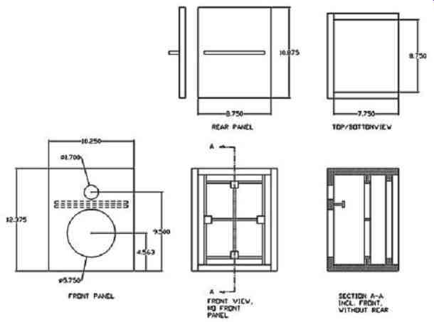
FIG. 1: Cabinet design.
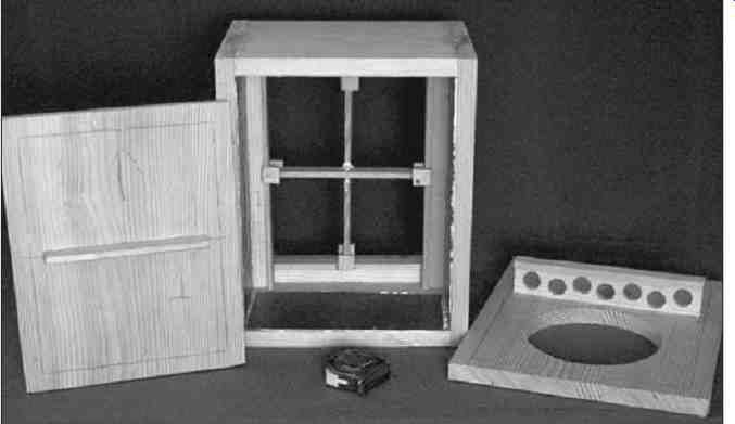
ABOVE: PHOTO 2: Cabinet components before assembly.
ELECTRICAL CONNECTIONS:
Internal wiring is Teflon-insulated silver plated, with fast-on type fittings at the speaker ends and spade lugs at the interior cabinet feed-through screws.
Those four rear-panel feed-throughs are pieces of 3/8” OD brass bar, drilled and tapped for 10-32 × 3/8” round head Phillips PEM screws (with integral lockwashers). I used a bench vise to press the chamfered feed-throughs into snug holes in the rear panels.
PRELIMINARY TESTING:
The woofers were broken in with low frequency sine waves while hanging in free air. I then measured driver impedances in-box using a B&K Precision function generator (www.bkprecision.com), digital VOM, and calibrated series resistor, plus calculator. Using Vic's software, I extracted the seven circuit element components (3 R, 3 L, and 1 C) which model the drivers, and e-mailed him the data.
Figure 2 shows the measured woofer impedance magnitude and the seven-element simulation impedance magnitude, and they match accurately enough for me! It also appears that I got lucky and hit the 80Hz box tuning. The tweeter impedance measurements (not shown) behaved similarly to those for the woofer.
CROSSOVER DESIGN:
Jason covers the crossover design process in the accompanying sidebar (below).
The woofer inductors aren't standard values. These were made by either removing or adding turns to inductors from Madisound (madisound.com), measuring their inductance periodically until target values were met within one turn.
Large capacitance values consist of combinations of non-polar electrolytics adjusted with film capacitors. Not ideal, but it seems to be working.
Vic's computer-optimized crossover values always result in very precise performance. Because we have no way of measuring completed system frequency response any more accurately than the first measurements, we just listen to the surrounds both as main channels and as side-channel surrounds for cinema sound, and evaluate what we hear. So far, we found no reason to alter the cross over component values, shown in Fig. 3.
The crossover region is seamless, and the radiation pattern is very wide anywhere in front of the speakers. This makes aiming them as surrounds a very non-critical task.
EXAMPLE STANDS:
You can see "provisional" (meaning ugly) stands made to support the surrounds in Photos 3 and 4. They are composed of a large wooden disk-shaped foot, 5' of steel electrical conduit, an upper hollow plat form/box containing the crossovers, and thick felt padding on top of the platform.
The upper and lower halves of the box are joined with piano hinges on each long dimension, with loose pins. By removing a hinge pin on either side, you can open the boxes. Sure beats unscrewing speaker panels to access the crossovers. Where the boxes close, I applied strips of foam tape to pre-load the hinges and eliminate buzzing.
Speaker wiring snakes down through the conduit and exits just above the foot through a grommeted hole, while screws in tapped aluminum bars embedded in the feet provide terminals for wiring to the amplifier. The three major components slide together and apart-I need only open the boxes and disconnect spade lugs and everything is quickly reduced to three easily stored pieces.
I must confess I clumsily banged my head against the mounted surround speakers (a speaker weighs 15.1 lbs) during initial setup and testing. This spawned the decision to always remove the speakers from the stands and put them on the floor when not in play- here in California I would eventually be very sorry if I didn't.
TWEAKS:
Once the speakers were playing on their stands, I made some tweaks to improve the sound. This consisted of replacing C1 for the tweeter and C1 for the woofer with better-quality non-polarized electrolytic capacitors from the Xicon BPH series (Mouser,.mouser.com). The result is improved clarity and naturalness.
Builders are encouraged to experiment with their favorite components anywhere in the crossovers. Our findings, for example, are that inductors sound best having the lowest DC resistance, thus the iron cores. These surrounds don't play at volumes high enough to risk saturating the core.
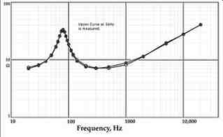
FIG. 2: Woofer impedance magnitude.
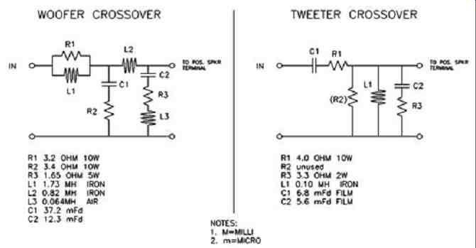
FIG. 3: Crossovers.
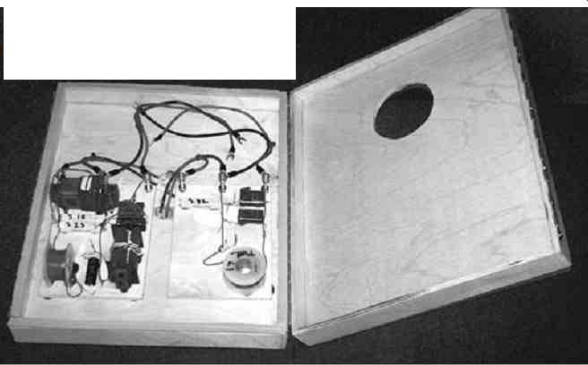
ABOVE: PHOTO 3: Crossovers in hollow platform.
SONIC IMPRESSIONS:
Test tones (from the Blu-ray player) were used to adjust the positioned surrounds in concert with the main speakers. A menu from the player allows each speaker to be attenuated in half-dB steps. When the system was finally checked out, some "challenging" movies were played, beginning with Digital Video Essentials.
The sonic personality of these surrounds ended up being essentially identical to my existing front channels, equipped with Focal midrange and tweeter drivers. This match makes the surround channel information merge seamlessly with the aural field from the main channels, and envelops the listener in a single continuum of sound. Echoes, decay, and other large-scale sound field effects are convincingly reproduced.
The movie background music sent to the surrounds is a continuous extension of the front-channel music. This may or may not be "real," but it is very appealing. And yes, the Aston Martin driving experience is back with a vengeance, better than ever.
CONCLUSION:
Coastal Douglas Fir is performing admirably. At performance listening levels the surrounds tend to disappear into the sound field. That is the target use of these speakers, so my objective has been met. Thanks to the high quality of the drivers and the optimized crossovers feeding them, they sound very good even used as freestanding mini-monitors, where they image and detail beautifully. There they rightfully de serve a subwoofer, which is exactly how Jason uses his Vanishing Loudspeakers.
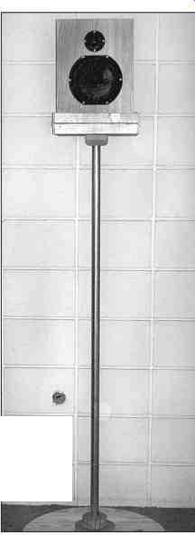
ABOVE: PHOTO 4: Surround on stand.
= = = = = = = SIDEBAR = = = = = = =
CROSSOVER CIRCUIT DESIGN
By Victor E. Staggs I measured the assembled surround speakers outdoors atop a ladder on Darcy's front lawn with the microphone at 1m, aimed midway between the two drivers.
The test signal was a 10-second sine wave swept between 20Hz and 20kHz. Figure A shows the measurements, with the levels normalized to the woofer's low-frequency efficiency. Frequency resolution was limited to 1/12 octave.
Reflections from the surroundings cause ripples. The woofer's peak at 4kHz and ripples above there are the real thing, and reproduce the manufacturer's spec sheet pretty well.
Below 300Hz the tweeter measurement consists mostly of background noise, which is also true for the woofer below about 80Hz.
FITTING THE MEASUREMENTS
Figure B shows the best fit to the woofer frequency response. At low frequencies the Thiele/Small model is used, and a collection of standard functions fits the rest of the measurement. The box diffraction signature consisting of a +6dB rise in amplitude above 200Hz is evident.
The target function for the crossover was an acoustic Linkwitz-Riley response centered on 2250Hz, the lowest practical crossover frequency for the tweeter. This yields good off-axis response from the woofer just below the crossover frequency.
The circuit topology chosen was that for the "Vanishing Loudspeaker".
The tweeter network was simplified by omitting the resistor to ground in parallel with the inductor.
The woofer and tweeter input impedances were measured and fit with the Thiele/Small model as it appeared in Reference 4.
Optimizing the Crossovers
The tweeter crossover was optimized by hand in software, using the impedance fit and the idealized Thiele/Small model of its frequency response, but having the measured acoustic efficiency. In this step I used the idealized Linkwitz-Riley low-pass response of the woofer. The resulting fit introduces a ripple of about +1dB in the summed response.
I optimized the woofer crossover using a nonlinear optimization program, feeding it the modeled woofer impedance curve and the analytical fit to its acoustic frequency response. The crossover was forced to produce a low-pass acoustic response at 2250Hz that yielded flat response when summed with the idealized Linkwitz-Riley high-pass response. In addition, I used a penalty function to keep the woofer input impedance, including the crossover network, from dropping below 7” .
The target function for these surround speakers leaves a 2dB rise due to the box diffraction signature. I tested this before hand using the original Vanishing Loudspeakers on stands near the front wall, and listening to the effect of filters applied to music via software, and including a subwoofer. When the surround speakers are used near a wall, this lack of bass fills in.
When used as main front left/right speakers, they will need to be closer to the front wall than most other speakers. This design choice was based on curves presented in Reference 5.
When used as main front left/right speakers, they will need to be closer to the front wall than most other speakers.
Figure C shows the modeled woofer acoustic response with the crossover in place, plus the target function (dashes). The tweeter response is the idealized Linkwitz-Riley fourth order high-pass response.
Figure D shows the modeled woofer acoustic response as filtered by the crossover (solid line), summed with the idealized high-pass response of the tweeter, along with three parallel curves that are the target function and error limits of ±0.5dB. So far we do not have anechoic measuring facilities that have better amplitude resolution than this.
The input impedance of the completed speaker is 6.5-7” below the crossover frequency and 3.5” above the crossover frequency. There is little continuous energy above 2250Hz in most music and sound effects, so this should be an accept able load for the amplifier.
The woofer's bass alignment matches the THX specification for bass management in A/V receivers and processors given in Reference 6.
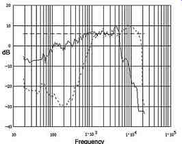
FIG. A: Woofer, tweeter measured acoustic frequency response.
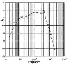
FIG. B: Analytical fit of woofer acoustic response.
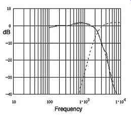
FIG. C: Modeled woofer response, plus idealized tweeter, with crossover.
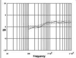
FIG. D: Sum of modeled woofer, idealized tweeter with crossover.
= = = = = =
References:
1. V. Staggs, "The Vanishing Loudspeaker," Speaker Builder 3/92.
2. Alden, R., "Advanced Speaker Systems", Master Publishing, Inc., 1995.
3. http://www.fpl.fs.fed.us/documnts/fplgtr/fplgtr113/ch04.pdf
4. V. Staggs , "Exploring Loudspeaker Impedance, " Speaker Builder 5/94.
5. Floyd E. Toole, "Sound Reproduction: The Acoustics and Psychoacoustics of Loudspeakers and Rooms," Focal Press, July 2008.
6. Holman, Tomlinson, "5.1 Surround Sound: Up and Running," Focal Press, 2000.
= = = =