Rube Goldberg meets the directly heated triode.
I have a confession to make.
Even though I’ve been experimenting with and designing with tubes for many years, I’ve never designed or built a single-ended directly heated triode amplifier. Until now, that is.
Single-ended DHT amps have always seemed too fashionable. I’ve always been more interested in doing something out of the ordinary. The high price of tri odes such as the 300B and the fact that I hadn’t heard many of these amps that re ally sounded great to me were also major contributors to my prejudice against these amps.
But all along I had this nagging question in my mind: was I missing some thing? After a fortuitous trade netted me a pair of new 300B tubes, I decided that I really needed to give it a go.
DESIGN GOALS
If I were to design and build a single-ended 300B amplifier, I decided that I should incorporate as many of the current design details for this amp that I could. After all, how better to find out whether any of them were worthwhile?
To this end, I deemed the amp needed to use interstage transformer coupling, fixed bias, DC and/or CCS filament sup plies, and mercury vapor rectification with a choke-input filter. Some of these design details have clear technical advantages associated with them—the advantages of others were not so clear to me. In any case, even if I wasn’t sure what the amp would wind up sounding like, I was certain that it was going to look cool!
Being the engineer that I am, of course, this also meant that I needed to include circuitry to delay application of B+ until the mercury vapor tubes had sufficient time to heat. And fixed bias meant I needed to design a very clean bias supply, and provide protection so that if the bias supply were to fail, the output stage would be protected from excessive plate current.
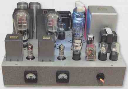
The result (Photo 1) is an amplifier that I call the “unnecessarily complex” 300B amplifier, because you really don’t need all of this complexity to build a good single-ended 300B amp. You could build the same amplifier circuit with a more conventional power supply with a lot fewer components. But, this is a hobby, not a business, and who says we need to be practical?
THE AMPLIFIER
The amplifier circuitry itself—that is, the part that the audio signal passes through—is really not complex at all. The schematic is shown in Fig. 1. The 300B output tube is coupled to the speaker via a Tango XE-20S output transformer.
The 300B’s grid is driven through a 1:1 interstage transformer (I used a Tango NC-14) by a two-stage amplifier using two sections of a 5687 or 7044 dual triode, DC-coupled to each other. I found both the 7044 and 5687 worked equally well, as should the 7119/E182CC tube. Power to the first stage needs to be decoupled with an RC filter; without it, I found that there is a considerable gain peak at low frequencies. Note that a large (and relatively high voltage) cathode by pass capacitor is required on the second stage to provide enough gain, and to keep the Z_out low enough to drive the interstage transformer, especially at high frequencies.
The negative grid bias voltage for the 300B is delivered through the interstage transformer. The bias voltage is adjustable via a pot, and is bypassed to ground with a 3.3RF polypropylene film capacitor.
My initial design used a single-stage driver, using a triode-connected EL802 tube, a very high-Gm pentode designed for video amplifier service. This design was simpler and actually performed slightly better than the two-stage design shown here. Unfortunately, it suffered from slightly lower than ideal gain, and high input (Miller) capacitance that made it problematic to use with a passive attenuator directly from a CD player. If you’re interested in this design (and don’t mind using a preamp), you can find the schematic on pmillett.com.
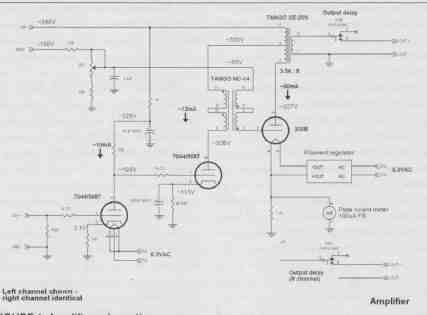
FIGURE 1: Amplifier schematic.

FIGURE 2: DC filament supply schematic.
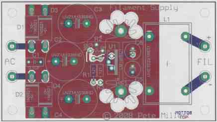
FIGURE 3: Filament supply PCB.
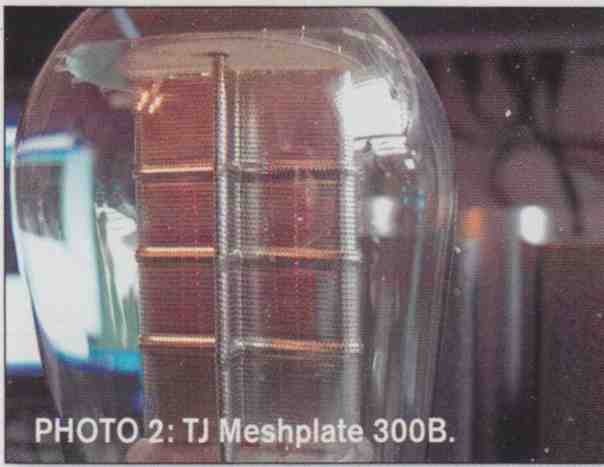
I chose to operate the 300B tube (I used the TJ meshplate 300B, shown close up in Photo 2) at a plate voltage of about 325V and a current of around 90mA, partly based on what I could conveniently generate using available power transformers. This is just under 30W of plate dissipation, well under the 40W maximum that most 300B tubes carry.
Plate current (actually cathode current) is metered to facilitate bias adjustment. I used some lovely little surplus meters (no, I’m not revealing my source!) that were graduated from 0 to 100. With a 1.2 resistor in parallel with the meter, this equated to a 0-100mA scale, exactly what I needed.
The only thing a little “different” in the amplifier circuit is that there is feedback taken from the ultralinear tap of the out put transformer, applied to the primary of the interstage transformer. I did this because I found the amount of distortion in the amplifier without it was a little too high for my taste.
The 300B filament is supplied with regulated DC provided by a circuit I de signed and built on a small PCB. The schematic of the filament supply (Fig. 2) consists of a bridge rectifier (using Schottky rectifiers) with a large capacitive filter, followed by an LM1085 (or LT1085) 3A linear voltage regulator IC. The output voltage is adjusted to 5V (measured at the tube socket under load). A common-mode choke such as those used in EMI filters is used at the output.
The PCB layout is shown in Fig. 3. You can download more details on the filament supply, including the PCB layout, from my website.
I designed the form factor of the filament supply so that I could also substitute a constant-current filament supply sold by TentLabs (tentlabs.com). If you don’t want to build your own, I definitely recommend the TentLabs supplies.
Another little complexity that you’ll see on the amplifier schematic is that there is a relay in series with the speaker outputs.
I found that if you delay application of B+ (which you must do with mercury vapor rectifiers), you get quite a “thump” in the speaker as the B+ rises. So, this relay mutes the speakers for a few seconds after the application of B+. More on this later.
POWER SUPPLY
In the power supply design (Fig. 4), the complexity is increased just a little. Because I wanted to use fixed bias in this design, I needed a negative bias supply. A sane person would just use a half-wave solid-state rectifier, but where’s the fun in that?
I used an inexpensive small plate/filament transformer (from Allied Electronics) and a tube rectifier using a 5AZ4 tube (which is essentially a loctal 5Y3). Filtering is via an RCLC filter, which delivers about -314V. Watch the capacitor polarity here—the output is a negative voltage! This raw supply is regulated by a shunt regulation circuit that I’ll visit in a moment.
For the main B+ supply, I used 866AX I mercury-vapor rectifiers. These are lovely, tall, slender tubes, which are interchange able with “normal” 866 rectifier tubes and many other mercury vapor and gas rectifier tubes. They certainly add some visual appeal with their bright blue glow (Photo 3).
These tubes require a 2.5V, 5A filament supply for each tube. I happened to have a pair of 2.5V 5A filament transformers sit ting around, so rather than buying a new 10A transformer, I used the two smaller units I had. This actually worked out well as far as the chassis layout is concerned— the transformers were small enough that I mounted them on standoffs directly under the 866AX tube sockets, which al lowed for very short and neat wiring.
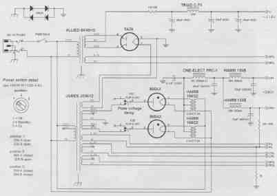
FIGURE 4: Power supply schematic.
Here’s a tip if you plan on using mercury vapor rectifiers: Because they can have condensed mercury inside, MV tubes can only be operated in an upright position. If you want to be able to run your amp on its side, to access the guts to make measurements or debug things, get a pair of 3B28 gas rectifiers. You can use these in place of the MV tube, and they have very similar characteristics and allow you to operate the amp in any position.
To supply the main B+ and all the amplifier filaments, I used a big multi- winding transformer from James, the JS9612. This transformer was designed for a conventional stereo 300B amp, so it has several filament windings in addition to the high voltage winding. Because the 866AXs have their own dedicated filament transformers, I used the 5V rectifier winding for the bias supply rectifier. Three other independent filament windings are used for the driver tubes, and the two 300B filament supplies.
Because I wanted the bias supply to be up and running and the 300B filaments to be preheated (along with the 866AXs) before the application of B+, I used a relay to switch the high voltage secondary going to the 866AX plates. This requires a relay that can withstand a fairly high voltage. I used a three-pole relay with a 6V AC coil that carried a contact rating of 600V AC, which is more than adequate for the job, and provides an extra pole that is useful for the time delay circuitry you’ll see shortly.
Though the 866AX tubes can with stand relatively high peak currents, they are normally used with choke-input filters. Because choke-input filters are also in fashion, that’s the route I took. I used a small film capacitor (0.1uF) to ground directly on the output of the rectifier, but its function is more as a filter for HF noise than ripple.
Unfortunately, it’s pretty hard to find chokes that work well as an input choke; most chokes available these days are not designed to have a large AC voltage applied across them. Normal filter (also called “smoothing”) chokes tend to be come hot and make loud buzzing noises when used as input chokes.
The only off-the-shelf chokes I’ve found in the US that are up to the challenge are actually sold as plate chokes for parallel-feed amps. If you think about it, it makes sense—a plate choke is also subject to large AC voltages, so must be designed a little differently than a standard filter choke. The choke I used is a One-Electron PRC-1, with its two windings connected in parallel to give SH at 200mA DC. Following the choke is a 40uF polypropylene-in-oil motor run capacitor, followed by separate LC filter sections for each channel, using conventional 10H chokes and 70uF PP-in-oil capacitors.
One other odd bit you see in the power supply is the arrangement of series/anti-parallel diodes that connect chassis ground to signal ground. This is a ground-loop-breaker circuit. The 5A- rated diodes will conduct if there is ever a potential difference of more than about 1.2V between the chassis ground (which is also the safety ground connected to the ground of the AC mains plug) and the amplifier’s power and signal ground. This breaks the path of ground loop currents caused by small differences in ground voltages between different components. In the event of a potentially hazardous condition such as an insulation breakdown in the power supply, current will flow through the diodes to the safety ground, preventing the chassis from becoming energized.
THE BIAS REGULATOR CIRCUIT
The upper portion of Fig. 5 shows the schematic of the bias voltage regulator circuitry. A 0D3/VR150 tube is used as a shunt regulator. Instead of a series dropping resistor to limit current through the VR tube, it’s fed from a constant-current source (CCS) using a 7AD7 tube, which is a high-Gm loctal pentode. It’s connected in pentode mode (note the capacitor from screen grid to cathode) and is configured to source about 25mA.
My reasoning for using a CCS here instead of a resistor was twofold: 1. The CCS provides noise rejection, acting like a big inductor. 2. I didn’t want to dissipate any more power inside the chassis than I had to. Using a tube CCS put the heat on top of the chassis where it belongs.
Between the plate of the 7AD7 and the cathode of the VR tube (remember, I’m talking about a negative voltage here), you will see the coil of a relay, K1. This relay is an old-fashioned 25OO1 plate circuit relay. (I was surprised to find that these relays are still manufactured!) This relay, which activates at 10mA coil current, is used as a bias interlock; unless this relay is activated (which implies that there is cur rent flowing through the VR tube, so the bias voltage is in regulation), the B+ relay cannot be energized. Similarly, if the bias supply fails, K1 drops out, immediately removing B+.
Because the 7AD7 cathode is sitting near -300V, its heater needs to be sup plied from a separate transformer winding so it can be biased to avoid breaking down the heater-cathode insulation. The bias transformer I used has a 6.3V winding that I used for this. One side of the heater is connected to the 7AD7 cathode.
The performance of the bias circuit is exceptional. I measured only tens of microvolts of AC noise (unweighted) at the 300B grid (with the driver disconnected). That’s at the threshold of my measurement equipment.
CONTROL CIRCUIT
The lower part of the schematic in Fig. 5 shows the control circuitry to implement the delays and interlocks I mentioned. Here you find the truly unnecessary complexity that would make Rube Goldberg proud!
I wanted to do something more elegant than to use a couple of toggle switches to control power. I ran across a very nice three-position lighted switch, intended for industrial control use. Then I designed a control circuit around it.
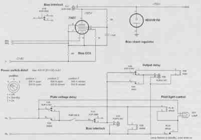
FIGURE 5: Bias regulator and control schematic.
The power switch is a two-pole switch. One pole is used to switch the AC line power; in the fully counterclockwise “off” position, this contact is open, and in the other two positions, it’s closed, applying AC power to the transformer primaries. The second pole is closed only in the fully clockwise “on” position, and it’s used to enable the B+.
The application of high voltage to the 866AX rectifiers needs to be delayed until sufficient time has passed to properly warm up the rectifiers, which requires at least 30 seconds, preferably 60 seconds. I wanted this to be an “automatic” feature, so you could turn the power switch all the way on without having to wait for the warmup time to pass and enable the B+ manually. I also wanted to make sure that B+ could not be activated unless the bias supply was operating, to prevent damage to the output stage.
I was tempted to implement the delays in modern fashion with a microcontroller but I’ve done that before—so I went with an old-school no-silicon approach using thermal time delay relays. Following is an explanation of how this relay logic works:
When AC power is applied (by turning the power switch to the middle “stand by” or fully clockwise “on” positions), the 6.3V filament voltage is applied to the pilot light (part of the switch assembly) through a flasher relay (FL1). The flasher relay is basically a thermal delay relay with a normally closed contact—it heats up and opens the switch, which turns off the pilot light and allows the relay to cool, until the contact closes and the cycle repeats. The result is that the pilot light flashes in standby mode, or when waiting for the rectifier tubes to heat. This is no doubt the most unnecessary complexity in the design!
At the same time, power is applied to the coil of a 60-second thermal time delay relay K2, which is used to delay the application of high voltage until the 866AXs have had 60 seconds to heat. Once the 60 seconds are up, the contacts of K2 close.
At this point, if either the power switch is in the “standby” position or the bias relay is not closed, nothing more happens. The amp happily sits there with the pilot light flashing and the tubes lit.
If the power switch is in the “on” position and the bias interlock relay is pulled in (which it should be unless the bias supply has failed), then the coil of K3 is energized. K3 is a three-pole relay—two poles are used to apply the high voltage to the 866AX plates, and the third is used to de-energize the coil of thermal relay K2, as well as to latch K3 in the on state. This is done so that the thermal delay relay has a chance to cool, preventing it from turning on quickly if power is cycled off then back on.
K3 stays in the energized state until either the power switch is turned to “off” (removing all AC power) or to “standby,” or until the bias interlock relay opens (which it should not do unless there is a failure in the bias supply).
When K3 is energized and B+ is applied, power is removed from the flasher coil, which is wired such that the pilot light is lit solid in the “on” state through the normally closed contact. At the same time, a second delay and latching relay circuit consisting of delay relay K4 and three- pole relay KS is activated, which keeps the speaker outputs muted for five seconds after the application of B+. After the delay, K5 latches on, enabling the output and re moving power from the coil of K4.
CONSTRUCTION DETAILS
I built the amplifier chassis from flat 3mm thick sheets of aluminum (for the top and bottom panels), and solid-surface countertop material (DuPont Corian). I had the aluminum fabricated for me by Front Panel Express (frontpanelexpress.com), which adds some cost to the project, but they can certainly do a much better job of it than I ever could—they do beautiful work.
I fabricated the body of the chassis myself using a scrap of ½” thick Corian I found on eBay. The countertop material cuts and drills pretty easily, more or less like a moderately hard wood with a very fine grain. I glued it together using a “slightly retarded cyanoacrylate adhesive” thanks to the advice of my friend Dr. Polymer—that’s slow-cure superglue to you and me—and polished it to a nice finish. I used threaded inserts (knurled brass) that press into drilled holes in the Conan to provide screw threads to at tach the chassis top and bottom plates, as well as a few of the components inside.
I used single-point terminals and the tube sockets to support the components inside. The tube sockets I used are the “wavy washer” type that mounts in a round hole without screws. Ground connections are to a bus-bar system that is also supported by single-point terminals.
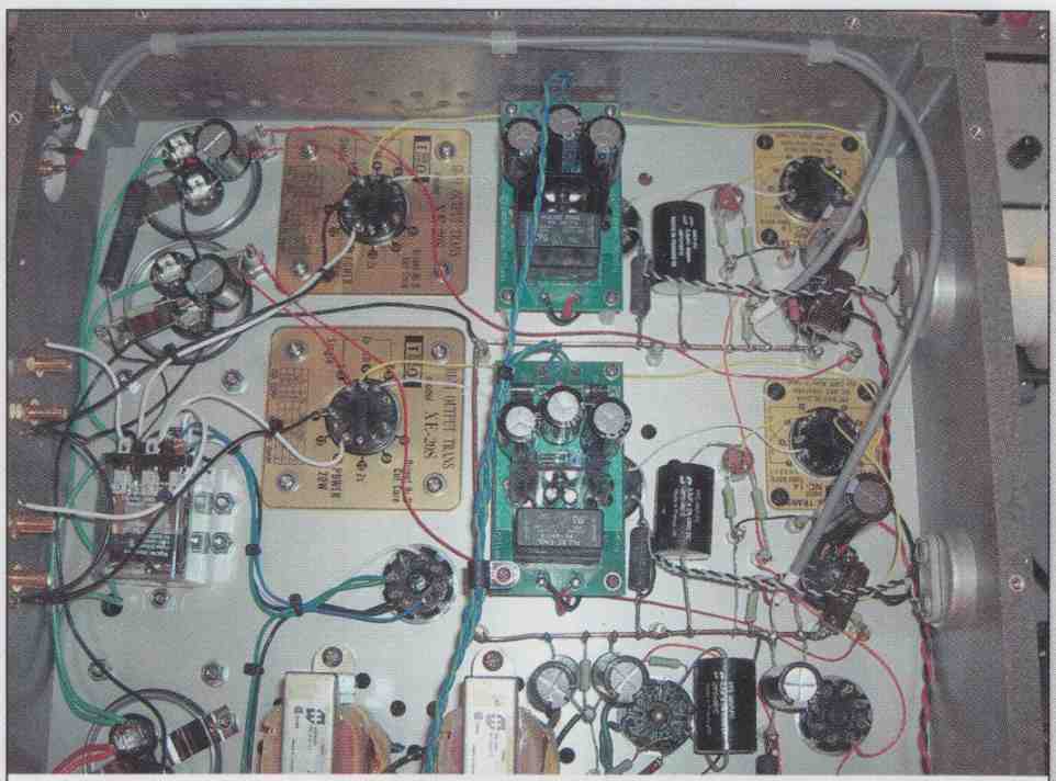
PHOTO 5: Inside wiring (left).
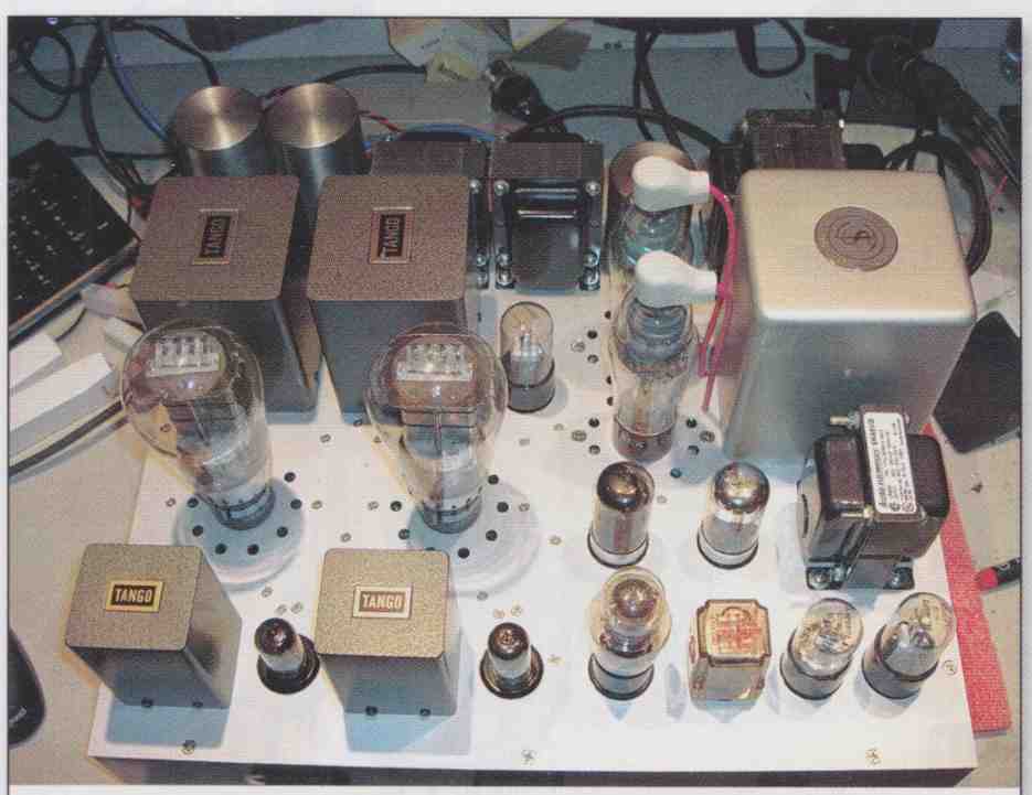
Photo 4 shows a top view of the chassis. The input choke is in the back corner of the chassis behind the main power transformer, located as far away from the interstage transformers as possible to avoid any noise coupling. The B+ filter caps and chokes are lined up along the rear of the chassis. The bias and control circuitry is located in the front right corner, and the amplifier circuitry itself is located at the front left corner, Figure 6 shows a mechanical drawing of the chassis and the overall dimensions of the amp. You can download details of the mechanical layout, including CAD mechanical drawings and Front Panel Express files, from the website.
In Photo 5, a view of the left-hand side of the underside of the chassis, you can see the input wiring, routed via shielded cable from the RCA input jacks mounted on back of the chassis to the input stages at the front. Also visible are the filament power supply circuit PCBs, which are mounted on standoffs directly underneath the 300B sockets. You can see the muting relay at the left side near the speaker binding posts.
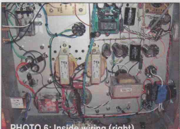
Photo 6 shows the other side of the chassis. At the bottom of the photo is a small terminal board from Keystone Electronics that I used to consolidate the AC line wiring between the power switch and the multiple transformer primaries. The two transformers in the center are the rectifier filament transformers, mounted on standoffs directly under the rectifier sockets. The filter choke for the bias sup ply is located to their right, mounted in a similar fashion, and you can see the power switch in the lower right corner. The HV relay is at the lower left, near the AC inlet—the thick red wires you see are silicone-insulated test lead wire, which passes through the chassis to the top caps on the plates of the 866AX tubes.
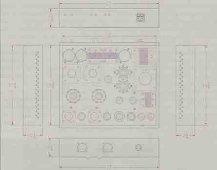
FIGURE 6: Chassis mechanical layout.
MEASUREMENTS
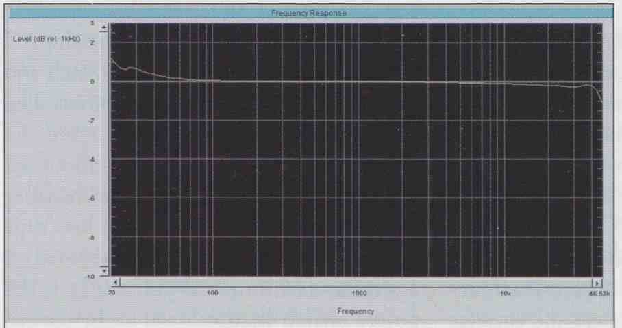
Figure 7 shows the frequency response of the finished amplifier at 1W out. Due (I assume) to phase shifts through the transformers at low frequency and the negative feedback path from the OPT to the interstage transformer, there is a small rise in response between 10Hz and about 30Hz. The amplitude of this peak is affected by the size of the cathode by pass capacitor on the first stage, increasing if a smaller capacitance is used.
HF response extends beyond 40kHz, where resonances and phase shifts pro duce some ups and downs in the frequency response, which eventually drops off at over 80kHz. This ragged ultrasonic frequency response is commonplace among single-ended transformer coupled amps and is a subject of some controversy. This response also manifests itself as ringing if a square-wave input signal with very high slew rate is applied, as seen in the oscilloscope capture shown in Fig. 8.
Every attempt I made to tame this high-frequency nastiness resulted in an increase in HF distortion or an unacceptable drop in HF response, so I left it alone.
As long as the input signal doesn't con tam much energy at these frequencies- which normal, well-behaved audio sources should not—I don’t see any reason why this response should cause any problems.
Figure 9 shows a plot of THD + noise versus frequency at 1W output into 8-ohm. As you normally see in this type of amp, THD rises at both low frequency (due to transformer nonlinearities) and at high frequencies.
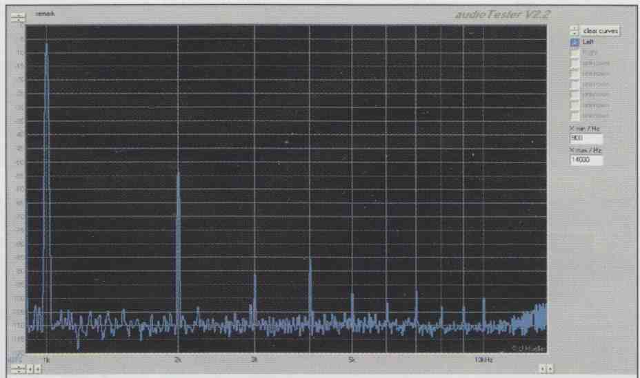
Figure 10 shows an FFT spectrogram of the amplifier output at 1kHz and 1W. As expected of a single-ended amp, the distortion spectrum is dominated by the second and fourth harmonic. The third harmonic is over 90dB below the fundamental.
Finally, Fig. 11 shows a plot of THD + noise versus output power. Due to the well-filtered power supplies and DC filament operation, this amplifier is very quiet; not much noise appears at the low end of the plot. THD increases as expected with increasing power. The onset of clipping occurs at approximately 7W, and the THD rises rapidly past 5% above about 8.5W. Note that this is with the output transformer connected with a 3.5k-ohm load impedance on the 300B.
LISTENING IMPRESSIONS
What does it sound like? Well, it sounds like a single-ended 300B amplifier!
Connected to my Jordan JX-92S speakers, I found the sound to be some what muddy, like many other SET 300B amps I’ve heard in the past. I think this is partly due to the Jordans’ inefficiency— I think driving them with an amp that puts out 7 or 8W is asking too much. The Jordans also don’t respond well to a high source impedance, which probably contributed some to the lackluster performance as well.
I had much better results listening with my higher-efficiency Fostex-based speakers. Initially, I found the sound of this combo a little too wild—somewhat underdamped bass and a little rough on the high end. I re-wired the output trans formers for a 5k plate load instead of 3.5k, which results in a little less power, but lower distortion and lower output impedance. This eliminated the problems, so I listened extensively to this combination.
As you might expect, some types of music sounded better on this system than others. Vocals, both female and male, were very special. There is a sense of realism that I don’t get with many of my other amplifiers. The soundstage was also extended, and I noticed small details that I don’t always catch with other systems. Simple arrangements of piano and acoustic guitar attained a high level of realism—no small feat, especially when it comes to piano.
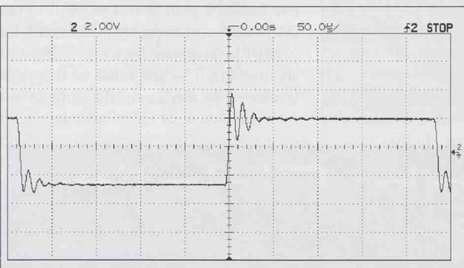
FIGURE 8: Square-wave ringing.
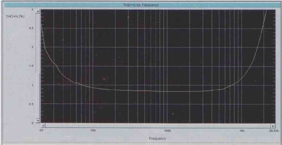
FIGURE 9: Distortion vs. frequency.
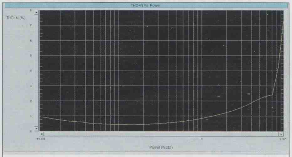
FIGURE 11: THD + noise vs. output power.
On the down side, things became a little muddled when listening to complex, dynamic music. I’ve found this to be true in the past when listening to amplifiers with large amounts of even-order distortion.
CONCLUSION
For me, this amp did not produce any revelations—no “sonic nirvana.” Don’t get me wrong—this amplifier sounds very, very good. But for me, it does not sound significantly better than other amplifiers I’ve built—just different.
The overall sound of an audio system has much to do with matching the pieces together to get the sound you like with the music you listen to. Arguably, my system—and my speakers, in particular— may not be the most synergistic with a single-ended 300B amp.
As for the audiophile fashion trends I included in this amp design, including interstage transformer coupling and mercury-vapor rectification, I cannot confirm or deny for certain that they had any impact—positive or negative. They certainly performed well, but I remain unconvinced that they’re necessarily superior to other implementations.
But I haven’t given up. I’m now shopping for some new high-efficiency speakers.
Some Notes on Components
Whenever I publish a design, I receive many questions about component selection and sourcing. Unfortunately, with a design like this, there are often parts that I used that may be difficult or even impossible for potential builders to source. Following are a few suggestions:
Output and interstage transformers
Tango transformers, such as the XE-20S and NC-14 I used, are expensive and difficult to obtain in the US (actually, in most of the world outside Japan). You can order them directly from Japan from EIFL export (www.eifl.co.jp), but shipping is ex pensive. So unless you are willing to fly to Japan to buy them in person (which I heartily recommend, by the way), you may want to substitute something else.
The output transformer can be replaced by pretty much any single-ended OPT with an ultralinear tap, using an impedance ratio of 3.5k:8 or 5k:8, whichever you prefer. The interstage transformer is a little more problematic, because not many vendors manufacture good interstage transformers. About the only vendors I can recommend (other than Tango and Tamura of Japan) are Lundahl from Sweden, which is well distributed throughout the world, and Electra-Print in the US. Electra-Print (www.electra-print.com) builds custom transformers to order, and can, no doubt, build appropriate transformers for this design at a reasonable cost.
Note that the performance of the amplifier can be affected by the choice of transformers. Especially when there is feedback involved, as there is in this de sign, some experimentation may be needed if different transformers are used.
Power transformers
Unfortunately, James, which makes the main power transformer that I used, no longer has a US distributor. You can order directly from James in Taiwan—I have had reports that this is not too expensive, and shipping is reasonably quick. If you don’t want to go that route, there are several other options. You can use multiple transformers and assemble an equivalent of the James unit using stock transformers from Hammond or other makers (for example, using a plate transformer with SV and 6.3V filament windings plus two separate 6.3V filament transformers for the 300Bs). You could also have a power transformer custom wound, which can be accomplished by many companies, including Electra-Print.
The bias supply transformer I used came from Allied Electronics (alliedelec.com), and there are other models from Hammond or other sources that you could use here as well. The same can be said of the rectifier filament transformers—the ones I used came from Hammond.
Chokes
As mentioned, the main B+ input choke needs to be rated for choke-input service. The One-Electron PRC-1 choke, available from Antique Electronics (tubesandmore.com), works well. Another option is to find a military surplus choke, either on eBay or at a surplus dealer such as Surplus Sales of Nebraska (www. surplussales.com). If you have access to Japanese iron, Tango and Tamura make choke-input chokes as well, though they are expensive.
The second-stage filter chokes are not as problematic—I used some custom-wound chokes I had on hand, which you can re place with chokes from Hammond or other manufacturers. The bias choke is not critical—you can use an inexpensive choke from Triad Magnetics (available through the usual distributors) or from Hammond.
Relays
The relays I used are all still in production, though some of them are best bought from surplus dealers. The delay relays and flashers are made by Amperite, and are available from tube vendors, Antique Electronics, or eBay for less money than from mainline electronics distributors.
The plate circuit relay used for the bias interlock is a Potter & Brumfield (now owned by Tyco Electronics) KCP-11-2500. This is a 2.5k-ohm coil relay in an octal-based enclosure. The B+ and speaker muting relays are P&B KUP-series 3PDT relays with a 6V AC coil, part number KUP-14A55-6. The contact voltage ratings of this relay are a little confusing, but the label on the relay reads 3A, 600V AC, which is more than adequate. I found both of these relays in stock at Newark and at Master Distributors (masterdistributors.com). You can also find equivalent relays at surplus dealers.
Capacitors
The main filter capacitors used are polypropylene-in-oil AC-rated capacitors normally used for motor run applications. These are made by companies such as ASC, GE, or Commonwealth Sprague, and I’ve found the best deals for these are on eBay. The bias supply filter capacitors, input stage B+ filter caps, and cathode bypass cap on the second driver stage are electrolytic. I like to use low-ESR caps from Nichicon, but you can use what ever cap you like here. You may want to experiment with paralleling a small film capacitor across these—that is one tweak I haven’t yet experimented with.
Plate current meters Analog meters are becoming hard to find, especially small, high-quality units. They are still manufactured, but can be very expensive. Your options include surplus—if you can find what you need—or new production from companies such as Simpson or Tripplett. There are also meters sold specifically for tube amps that are very nice, though I don’t know of a US source—for example, Yamamoto in Japan (the seller of uber-expensive Teflon tube sockets) sells them (expensive, of course).
The best bet is a tube amp parts vendor in Belgium called Aquablue (diyparadiso.com). These very attractive and reasonably priced meters are small enough that postage is not an issue. Tell Benny I sent you.
The power switch
The power switch I used is made by Idec, part number HW1F-3F11QD-A-6V. This modular switch can be assembled a zillion different ways. I found that Master Distributors seems to stock virtually every combination. Study the datasheets found on the Idec website. You can even pick your own pilot light and trim ring colors.
