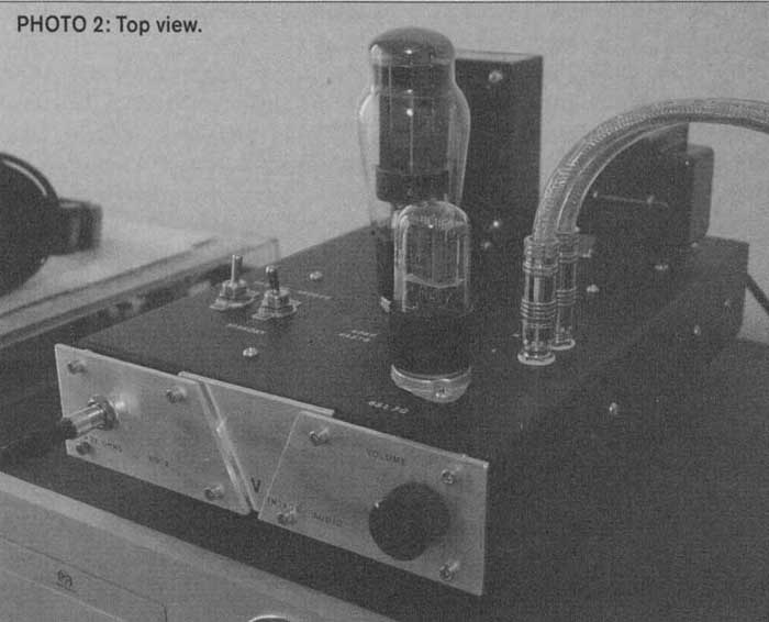
This vacuum tube headphone includes a 6SL7GT for the input stage and a 6A57G for the driver.
Listening to music, movies, TV or YouTube, using headphones, is a different type of audiophile enjoyment (compared to loudspeakers). Headphones resolve reproduced sound much better than loudspeakers. Headphones are a must-have tool for professional and monitoring applications.
I began searching for a vacuum tube headphone amp, because solid-state circuits were getting a bit boring. The glow of vacuum tubes gives a relaxing ambience to a room in the evening. I was also looking for a gift for a teenager, who moved off to college, and I thought a headphone amp would be ideal for a college dorm. He could listen to what he wants—whenever and however loud— without disturbing anyone. He was interested in the tube sound system I have at home, as well as the old technology that can rival many newer solid-state systems.
PROS & CONS:
I decided on a class-A, single-ended output for several reasons.
A headphone amp can operate with very low wattage. A class-AB amp would be too powerful and, anyway, would linger in the class-A portion nearly all the time with such a low output. The power demand of head phones would never reach class B. Class A has more distortion than class AB, but the power demand of headphones makes the load-line so short that it lies on a linear part of the tube’s characteristic curve. Class A second-order distortion increases proportionately with the output power.

Unless you’ve suffered major hearing loss, you’ll never drive this amp into audible distortion. The disadvantages of class A are the wasted heat and poor power supply rejection. The latter is significant but can be overcome. Head phones can be unforgiving with hum or noise, so you need good power supply filtering.
First, a few words about safety.
This project has potentials near 300V. Get some help if you are unfamiliar with high potential tube circuits. Perhaps someone you know can inspect and do the initial power-up for you. I always use a Variac to slowly power up new equipment.
I also use a three-prong power cord. Ground the chassis so the fuse will blow if there is a major fault or if the chassis becomes energized. Fuses, which are very cheap, are the first thing the hot line goes to when it enters the chassis.
I’ve seen other DIY designs with the neutral fused instead of the hot line. This won’t offer protection if there is a hot chassis or a loss of neutral. I’ve also seen DIY projects that switch the neutral instead of the hot line. You should always place the power switch on the hot. I service industrial equipment in my day job, and the hot line is always fused and switched.
Add up all the volt-amps used in all the transformers. Divide this by 120V and the result will be the current consumed from the line. You will need a little lagniappe [extra measure of safety] to get the fuse through turn-on surge without blowing, so multiply the steady-state current by 1.5. I ended up using about 0.5A, so I used a 0.75A fuse.
SPECS:
I wanted to experiment with a headphone driver with no transformer between the output tube and headphones. I sometimes use a pair of Sennheiser HD-280s with an impedance of 64-ohm, 102dB sound pressure level at 1.0V_RMS. I also use a pair of Sennheiser HD 600s with an impedance of 300-ohm, 97dB at 1.0 V_RMS. I would need a low output impedance to drive these headphones. A cathode follower would work well in this application.

above: The completed DIY amp.
I began browsing my RCA tube manual for a tube with certain characteristics. The output tube would need high transconductance, low plate resistance, and the capability of relatively high plate current. I looked at common audio power tubes such as 6L6G and 6550, which didn’t fit all the criteria because of plate resistance or current limitations. Then I remembered the 6AS7G, which was designed for regulated power sup plies but has also been successfully used for audio power OTL output stages.
The 6AS7G is designed to pass lots of current with little resistance. Its typical plate current is 125mA and plate resistance a mere 280-ohm. A great caveat: the 6AS7G is a twin triode; one envelope is good for stereo and it’s in current production at a reasonable price.
I like the choice of class-A triodes because the distortion contains mostly second-order harmonics with virtually no odd harmonics. Also, a cathode follower contributes virtually no Miller effect (the loss of high frequencies) because the gain is less than one. My headphones have impedances at or above 64-ohm, which is a good impedance match, but you should avoid using headphones below 64 for this project.
I again referred to my RCA manual and began designing the output stage. Typical operating parameters are 135V on the plate, 250 for the cathode resistor, and 125mA plate current. There are no plate curves in my RCA manual for the 6AS7G, but the curves are in a 1998 Fall Svetlana Audio Tubes book ( Fig. 1).

I wanted to operate this hot-running tube conservatively. I chose a 100-0- 100V plate transformer from the Hammond catalog to provide 120V plate supply. The next transformer option was too high. RCA recommends a cathode resistor of 250-ohm which I tried, but found it a little low for my application.
The 6AS7G ran 125mA as specified. I ended up using 270-ohm because I wanted 100mA plate current. You may prefer to run your tube a little hotter to achieve lower distortion. The 270 cathode resistor will bias the tube within its maximum operating conditions.
I could not tell the difference in listening tests, so I used a lower current bias for reliability and to extend the life of the tube. Fixed bias is not recommended because of potential thermal runaway on this power-hungry tube. Self-biasing also provided a small amount of degenerative feedback to help reduce distortion.
The Red Book standard for a CD maximum output signal is 2.0V_RMS, or 2.83V peak-to-peak. Table 1 indicates the signal level as it passes through the amp. An input of 2.0V yields a grid-drive of 9.12V at the 6AS7G. The peak-to-peak swing is 1.4 x 9.12 = 12.8V.
Therefore, the swing from quiescent current is ±6.4V. Figure 1 indicates this grid drive yields plate current of 65 to 145mA. The center of this swing is 105mA, but the quiescent current is 100. This is from the nonlinearity of the tube.
The distortion at this level is (105- 100)/100, or 5%. The RMS voltage swing at the cathode resistor is 7.64V. This is at maximum CD drive and 120dB sound pressure level (SPL) at the headphones! But music is dynamic and the average SPL will be much lower. At 84dB SPL, the distortion will be 1/64 that, or 0.078%.
The apparent loudness is halved for every -6dB SPL. 120dB - 84dB is -36dB, which is a -6dB drop—six times—so the level is halved six times, or 1/64. The 2.0V RMS specification accommodates the huge dynamic headroom of CDs. The average level is much lower. I don’t have a distortion analyzer, so these figures are purely theoretical.
COMPONENT SELECTION
In order to achieve unconditional output stability, I used R14 and R15 at the output, no global negative feedback, the grid resistors R14 and R15, and less than unity gain of the 6AS7G. The output of the cathode follower has a DC voltage, so I needed to compromise, using an electrolytic capacitor to couple the output with the headphones. Don’t be alarmed because the capacitor needs to block less than 30V DC.
Higher voltage caps can be expensive, but you can use your money here on quality instead of voltage. The output capacitor needs to be large enough to go down to 20Hz. The minimum load impedance is 64-ohm. The —3dB formula for capacitance is C = 1000000/(f * 2 * pi * R), where C is capacitance in microfarads, f is the cutoff frequency in Hz, and R is the headphone impedance.
C=1000000/(f*2*pi*R)
C = 1000000/(20*2*3.14*64)
C = 124uF
I used quality film bypass caps C14 and C16 paralleled with the output electrolytics C13 and Ci5. Resistors R14 and R15 bleed the output caps to keep the phone jack -at zero DC potential when in there is no load attached. This will keep your headphones from popping when you plug them into the jack.
I began designing the input stage next. Figure 3 is the complete schematic. I wanted to design the unit to operate at comfortable listening levels with the volume knob at about 25%. My intention here is to get good gain first, then throttle it at the input volume control.
I used a volume pot that was recommended in a solid-state headphone amp. I have used this Alps pot, which is sold by Radio Shack, on other projects with very good results. It’s very quiet and has good tracking between channels. When the volume pot is at 25%, or the 9 o’clock position, it’s at 75% attenuation. The volume attenuation is a log function, so log (3/4) = -0.12, or 12%.
I looked at common voltage gain tubes such as 12AT7 and 6SN7, but their gains were too low. 12AX7 looked OK but I prefer octal tubes, which have larger cathodes and anodes, to miniatures. I think this provides better imaging and presence.
This narrowed my search down to the 6SL7G, whose gain is in the upper 30s. This is a little high, so, again, I compromised. You may need the extra gain for sources other than a CD player or iPhone, and the lagniappe places my volume knob at 10 o’clock for comfortable listening. I used the data in the RCA manual which has an excellent section on resistance- coupled amplifiers, to design the 6SL7G input stage. I had a 250V plate sup ply transformer I wanted to use, but I needed to utilize some interpolation of the data between 180V and 300V.
This is how I arrived at the resistor values for the 6SL7G input stage. I didn’t use a bypass cap on the cathode resistor. This provided a small amount of local degenerative feedback and also reduced the excess gain in order to place the volume control position in a good location. Sometimes thing just come together. I did not like the RCA manual’s coupling cap recommendation with a high pass 100Hz cutoff
This was probably for AM tabletop radios. I wanted the frequency response to go down to 20Hz. Again, the 3dB point for capacitance is:
C = 1000000/(f 2 * pi * R), where R is the following stage’s grid resistance
C = 1000000/(20 *2 * 3.14 * 100,000)
C = 0.08
But this is the 3dB cutoff, so I elevated this by one decade to 0.8uF. A 1.0uF is the closest value I could find from Mouser that was a film capacitor with a 250V rating.
Table 1 shows the signal level as it passes through passive and active components in the amplifier. The CD player’s maximum output is 2.0V_RMS. This first goes to the volume pot and reduces the signal by a factor of 0.12 with the volume at 25%.
The signal leaves the pot at 0.24V and goes to the grid of the 6SL7G. The gain of this stage is 38, so the signal leaves the plate resistor at 9.12V and then goes to the grid of the 6AS7G. The gain here is about 0.838, less than one because it’s a cathode follower. The signal leaves the cathode resistor at 7.64V to drive the output jack.
==
TABLE 1
CD player, iPhone, etc. |
--> |
Volume pot |
--> |
6SL7G |
--> |
6AS7G |
--> |
headphones |
|
2.0v |
X0.12 |
0.24v |
X38 |
9.12v |
X0.838 |
7.64v |
120db |
==
OPERATION
The headphones have an efficiency of 102dB/1V_RMS. The dB level will be 20log (7.64V = +18dB above 102dB, or 120dB for maximum CD output. 2.0V RMS equals 2.83V peak.
From the characteristic curves in Fig. 2, a 2.83 grid drive yields a 1.50mA to 0.20mA plate current swing and 110V to 225V plate voltage swing. The middle of the plate voltage swing is 167.5, but the quiescent plate voltage is 177.
The distortion calculates as (177-167.5)/167.5 = 5.67%. At 25% volume, the signal level is 2 (3/4) * 5.67 = 0.71%. This distortion level in the first stage is for a SPL of 120dB at the headphones with maximum CD output. As I mentioned earlier about the output stage, this is for transient dynamic head room excursions. Typical average SPL will be around 84dB. Therefore, the distortion will be 1/64 of 0.71%, or 0.011%.
I could have chosen a more linear place on the characteristic curves to operate, but the gain would have been too high. Besides, headphones use very little drive, and I’m not driving loudspeakers to fill a room.
I performed an experiment with my Radio Shack sound level meter. I set the amp’s volume to 9 o’clock and measured C-weighted, slow response with the SPL meter. I tried several different discs and noted SPL values mostly around 66dB, but some discs were hotter and measured 74dB.
I observed 84dB rarely on peaks. I raised the volume to get an average 84dB and listening was unbearably loud. This raised my confidence level about the distortion of the amp because actual listening SPL levels will be much lower than the values I used to calculate. I believe the calculated levels are worst-case figures. For me, it was an educational exercise measuring real dynamic music sound levels.
Also of interest, the action level for noise exposure is 85dB. Hearing protection is required for workers who enter a zone at or above 85dB. How many of you wear hearing protection around the home mowing the lawn, For example?

Above: Fig. 2: 6SL7G characteristic curves.

Above: Fig. 3: Amp circuit.
POWER SUPPLY
The power supply is in Fig. 3. Switch S1 energizes T2 and T3. This is turned on first to energize all tube heaters and the 6SL7G plates. I wasn’t too concerned about cathode stripping in the 6SL7G. I’ve serviced many old tube amps, and the driver tubes in the voltage gain stages always outlast the power tubes. I believe power tubes are more susceptible to cathode stripping because of the higher voltage and plate current. The 6SL7Gs operate at very low current and have a 250V plate supply.
In contrast, most output power tubes operate nearly twice that potential. Al though the 6AS7G operates at only 120V in this design, it draws a tremendous amount of current from the cathodes. Therefore, good thermionic emission is needed to avoid cathode strip ping. This is why I chose to delay the plate supply to only the 6AS7Gs.
T2 provides the plate supply voltage to the 6SL7G. The voltage is full- wave rectified, and then a simple pi filter is used with plenty of capacitance. R2 is there to bleed the stored voltage down below 25V in one minute after the power is switched off. This is for your safety and convenience if you need to open the chassis for modifications or service. T2 also powers the 6AS7G heaters. This is also rectified, but more about that later.
T3 supplies power to the 6SL7G heaters. I always rectify heaters used in line-level gain stages. Eliminating hum is critical in the design of a headphone amp because your eardrum is only a few inches from the diaphragm. R3 was meticulously chosen by experimentation to arrive at 6.3VDC.
I am confident you will have success using the parts listed in Table 3. You may have different results if you use different diodes or transformer, but this should get you within heater specifications. Ti supplies the plate voltage for the 6AS7G. R4 drops the rectified voltage to 120V DC. R4 also provides a time constant to charge C1O. Ninety percent of voltage takes about one-half second and gives a smooth application of the B+.
You may have noticed by now that Ti cannot be energized without Si turned on. This allows you to manually delay the application of the 6A57G plate supply. It’s impossible to turn on the 6A57G plate supply without the heaters. If you turn on S2 first, then nothing happens.
The proper power-up order is first turn on S1, then after 45 seconds, turn on S2. You can incorporate an auto mated delay for S2 with an on-delay timer-relay. I prefer the manual switch because I also use S2 for a mute/standby switch if I want to unplug interconnect cables when I change input sources. I thought about adding a source selector input switch but I wanted to keep this simple.
You may have noticed that there is no bleeder resistor for the 6AS7G B+. This tube draws so much current that it will dump C10 quicker than the cathode can cool down when the amp is shut down. I used solid-state rectifiers on this project because I could not find a tube rectifier that could handle the high plate current demand from the 6A57G.
On completion, I tried several types of headphones of different impedances to ensure compatibility. I originally used AC voltage on the 6A57G heaters because there is no gain in this stage to amplify the hum. I didn’t think any hum would be picked up in this stage but I was very wrong. My 25-year-old Yamaha headphones sounded very nice and dead quiet, but the Sennheiser HD-600 had very slight hum. The Sennheiser HD-280 hummed even louder. The correlation was increase in hum with de crease in impedance.
I decided to try rectifying the filament voltage on the 6A57G. I researched the Mouser catalog for high current diodes and used a conventional silicon rectifier. I was on the right track because the hum was gone in all three types of headphones but the filament voltage dropped to 5.8V. The forward voltage was too high from the silicon rectifiers.
TABLE 2:
tube |
6sl7g |
6as7g |
filament |
6.30v |
6.30v |
plate supply |
250v |
120v |
plate |
177v |
120v |
cathode |
1.73 |
26.0v |
I consulted the Mouser catalog again for a high current, ultra fast switching, soft-recovery diode and arrived at the 512-RURP860 rectifier. This was better but a little low at 6.0V. My Svetlana publication gave 5.7V to 6.9V for filament tolerance. This was the best I could do, so I compromised and accepted what I had. Table 2 gives a list of voltages to look for when you power up for the first time. I adjusted my Variac to 120V AC; your measurements should be ±5%.
CONSTRUCTION:
I was very careful about the grounding scheme. A star ground is a soldering nightmare, so I made a ground bus from stripped wire. Each component in the circuit that goes to ground has its own lead to this ground bus. I kept the ground bus as short as possible, and close to the input jacks. When soldering a new wire to the ground bus, the heat will melt the solder joints of the other ground leads and the leads will separate from the bus.
I shaped the ends of the lead wires into hooks so they would stay attached when soldering other leads to the ground bus. The chassis is connected to the ground at only one point, the head phone common lug. Be sure to scrape the paint and bond to the metal. The ground bus is ultimately connected to chassis ground at this point and only at this point.
Ground the shields of shielded input cables only at one end. Tightly twist all A/C power leads and keep them a good distance from the audio path. The A/C neutral is not connected to the audio ground or the chassis ground. In the US the neutral is connected to ground out side at your service meter.
I used a Hammond steel chassis because steel will offer some protection against electromagnetic interference (EMI). I’ve included some figures to help in construction. You may use your own imagination to achieve more personalized results. Figure 4 is a hole-pattern for the top and sides of the chassis.

All bolts are 6-32 machine screws. Some are tapped but the size B holes are for mounting hardware on top as well as solder tag-boards underneath with a 6-32 nut fastener. I suggest purchasing all components first, then verify bolt patterns and sizes before drilling or punching. I like to cover the entire chassis with masking tape, and then I mark the holes before using a center punch.
This will protect the chassis’ finish while you’re drilling, punching, and cutting. You can use the faceplate design as shown in the photos. You can be very creative with aluminum flat-bar to make your projects a personal statement and aesthetically pleasing.
I drilled a pattern of vent holes on the top and the bottom cover plate to allow the chassis to breathe. The bottom feet are tall and give plenty of space between the bottom and the surface where the amp is placed. I use rub-on lettering to mark the chassis in all my projects.
I have some that are over five years old. I am careful when handling them, but if you prefer, you can apply polyurethane clear-coat, which will last forever. I placed the RCA input jacks on top of the chassis for convenience. I have always hated blindly reaching behind equipment to plug in cables.
My nephew used this amp for a few months before it blew a fuse. I measured more than 50V on one of the 6AS7G cathode resistors. Failure analysis indicated the plate current was much too high. I unsoldered the coupling capacitor C11 and the plate current dropped to the correct value. The coupling capacitor was leaking DC voltage to the 6AS7G grid. On inspection, the outer wrapping of both C11 and C12 were peeling back from excessive heat.
I had placed these delicate polypropylene caps too close to R12 and R13. These cathode resistors each dissipate 2.5W and cooked the coupling caps, so be careful of the component layout. I relocated two new coupling caps and replaced the cathode resistors, too. I checked the 6AS7G tube on my Hickok transconductance tester and it checked out good and matched on both sides. This was an old RCA New Old Stock (NOS), a very, rugged tube. The fuse did a good job, too.
This tube and the 6SL7G are still in current production at very reason able prices. You can also obtain a NOS version of it. You may try substituting the 6AS7G with a 6080. This is the industrial equivalent, but I like the curvy shape of the 6AS7G better than the straight bottle 6080.

Fig. 4: Chassis layout
SUMMARY
This small amp is designed to drive headphones with impedance at or above 64-ohm. It will drive lower impedances but will lose the deep bass. I tried to design this amp to give 20-20kHz, -3dB, and the finished unit performs quite well with low distortion, too. Some compromises were made, but I think this is a satisfying headphone amp that will provide years of enjoyment. All the parts I chose are common, available, current production, and reasonably priced. I achieved the major goals of zero global feedback and class A in both stages. The output coupling capacitors’ value is large enough to drive 64 headphones down to 20Hz.
A larger electrolytic capacitance could drive lower impedances, but would con tribute nonlinearities. I’m amazed at the detail in small jazz band recordings, especially listening to plucked upright bass. The texture of brushes on drum skin is much more detailed than any loudspeaker I’ve heard. Larger orchestral pieces don’t sound congested because of zero global negative feedback. This provides good imaging as well. I hope to hear from you with any comments, suggestions, or critique.
REFERENCES / RESOURCES
1. RCA Receiving Tube Manual RC-30, 1975.
2. RCA Receiving Tube Manual RC-30, 1975, p.
3. 1998 Fall Svetlana Audio Tubes, p.
4. RCA Receiving Tube Manual RC-30, 1975, p. 171.
5. audioXpress , Nov. 2005, p. 38.
6. RCA Receiving Tube Manual RC-30, 1975, p. 645.
7. RCA Receiving Tube Manual RC-30, 1975, p. 642.
8.1998 Fall Svetlana Audio Tubes, p.
Special thanks to these vendors who make this hobby possible:
- Mouser.com
- Antique Electronic Supply
- www.tubesandmore.com
- Radio Shack
- partsconneXion -- www.partsconnexion.com