Removing the Six “Straight Wire” Kinks: Prologue to a Better Preamp
Here are some — perhaps forgotten — tips on preamp design.
I finally needed to replace my “preamp,” which was nothing more than a stepped attenuator and four jacks in a small aluminum frame. It just didn’t look right, and was a bit limiting when changing sources. Plugging and unplugging cables have just too many disadvantages.
It’s often said that the best preamplifier is a “straight wire with gain.” But I don’t think we should set our sights that low.
Electric circuit theory is a simplification of how circuits behave. Even in the limited scope of this theory, wire has three characteristics of concern: resistance, capacitance, and inductance. Many audio effects are not well covered by this approach— For example, what happens when a semi-conducting crystal forms in a conductor—but circuit theory is a good starting place.
FACTORS
It may be simplistic to assume that you want the lowest resistance possible without considering the actual use. The source impedance of most consumer audio gear is about 100 at low frequencies rising at higher frequencies, designed to be loaded by at least a 10,000 load. When you have resistance in the “straight wire” conductor, there is a loss of signal level. Three feet of 24-gauge wire loaded by 10,000 has a loss of about 0.0000779dB. Increasing the wire to 10 gauge drops the loss to 0.00000258dB. In audio there are gifted people who do hear more than others, but not in this case.
The second concern is capacitance loading the signal source. The 3’ cable loads the source causing a loss of about 0.011dB for low source impedance to 1.16dB with a rising to high source impedance. The phase shift may run from just under 10 to more than 7° at the upper frequencies.
In the worst case this is something a critical listener could hear. When you consider that the signal probably goes through two or more cables (they may be longer than 3’), the signal source probably does not drive capacitive loads as nicely as pure resistive loads, and the capacitance may even be nonlinear, then you begin to see where one “straight wire” problem lies.
The issue of inductance is a bit different. Resistive losses don’t vary with frequency. Capacitive losses increase with frequency, as do series inductive losses. The difference is that capacitive losses load the source, while inductive losses raise the load impedance. Inductive losses are also greater at high frequencies. In the 3’ cable you see a loss of about 0.00785dB at high frequencies compared to 0.00000000785dB at the lowest frequencies. Is it possible some could hear this? Probably not!
MORE CONCERNS
The next problem of the “straight wire” are the six sources of noise it’s susceptible to: radio frequency interference (RFI), capacitive coupling, magnetic coupling (or mutual inductance), common source impedance, vibration, and moisture.
I treat RFI as a separate source because it’s usually from a far-off source. In reality it’s a combination of capacitive coupling and magnetic coupling. The cure is to shield the wire and gear, even though that adds capacitance and signal loss. Shields also have the problem known as skin effect—the lower the frequency of the RFI, the farther it can penetrate the shield. RH often shows up as added noise or grit to the sound.
Capacitive coupling of noise can be treated by field theory or approximated by circuit theory. For the circuit theory approach, assume there is a small capacitor hidden in the circuit that couples the “straight wire” to the noise source. You can also model a capacitor to ground from the conductor and even allow for some attenuation from a shield.
Magnetic coupling depends on the area of the conductor and strength of the field. Moving the power transformer away from sensitive areas is always a good idea. Making circuit paths shorter also provides benefits. If the “straight wire” is a real cable grounded at both ends, it’s almost certain that you will have a magnetically induced voltage.
Common source impedance is why lights flicker when a motor starts. When the desired signal shares a signal path with something else, the other signal causes a voltage drop in that path. If the other signal varies—say, from noise or even signal—that variation and its companion voltage drop shows up in the signal path.
Vibration is always present. Insulated wires will have triboelectric noise. Capacitors will react by modulating the spacing between electrodes and hence their capacitance, resulting in an AC voltage from any bias placed across them. Inductors may have movement in their windings, causing value shifts. Even some resistors may generate noise from movement.
Moisture, of course, can cause corrosion. Whenever two different metals touch and moisture is present, you produce a small noisy battery. Many folks find always leaving their gear on makes it sound better. Some of this is due to heat reducing the moisture in components such as resistors and capacitors. Both are affected to a small degree by moisture. Of course, the biggest problem can occur in switches, where the moisture may cause oxidation of the contacts. Sulfur or other compounds in the air make this even worse.
The final issue in the “straight wire with gain” is gain. If you are using an iPhone, CD player or tuner as your music source, both of these are capable of delivering 1V RMS. Some high-powered professional amplifiers will produce fill power with less than that. Even a low gain (26dB) power amplifier will deliver 50W with that input. So for many cases you don’t need gain— you need loss! Of course, if you have inefficient loudspeakers or perhaps want tone control, then you may want some gain.
SHIELD SOLUTIONS
It’s misleading to think of gain as only voltage amplification. You may wish to increase the current available to the load. This helps to reduce the effect of capacitance or other loads inside the power amplifiers or connecting cables.
It turns out there is a nice simple solution that will almost completely eliminate capacitive loading of interconnecting cables, increase the effective attenuation of the shield, and add almost no noise of its own.
That solution is the driven shield. In stead of surrounding the signal carrying wire with a grounded shield, use one that carries the same signal! Now the capacitance is not to ground but to the same voltage. The insulation can be nonlinear, because there is no voltage across it, no nonlinearity. The inductance of the wire is very slightly reduced by solenoid effect and some reverse capacitive coupling, although this is not really of practical value.
For RFI the interference now must travel through an extra isolated shield, so this one change multiplies the loss of a single shield. Same deal for any capacitively coupled noise.
To get even trickier, you can now cover this shield with a second insulated shield, which will prevent the signal from inside leaking out and contaminating the ground or return reference signal. If you twist a single conductor wire around this second shield and use this as the ground reference, this will help to reduce magnetic coupling. You get some of the advantages of a balanced line in the single-ended cable.
Of course, to keep the RFI out of the ground, you should add a third shield. To minimize the undesired energy, the second and third shields are grounded only at the driven end. This prevents mutual impedance of the shielding system from entering the signal path.
You can add a buffer amplifier at your source to power the driven shield. Of course, if you don’t want to modify your existing gear, an easier way is to put all the buffers in a new preamp. The buffers need to be decent, but not great amplifiers. After all, they will be attenuated by the amount that used to be ad equate just for noise. This is a good place for amplifiers such as the TL072 or any FET input amplifier, because they are less susceptible to RFI. Of course, you probably can even get away with a gold en oldie such as an NE1558. I mixed them up to see whether I could hear a difference.
In my design I used several small cards to become input or output circuits ( Fig. 1). The sending source can be a CD player, DVD, tuner, and so on.
I designed two versions of the buffer card. One is a send card designed to bridge the output and provide a modest current signal to the first active shield. It also tries to make sure all common mode currents are accounted for properly. It does this by grounding the source of the active shield’s current at the source. The return signal wire, which was the ground and shield in a normal cable, is now just a wire going to the common of both connectors. The final outer third shield is there to try and scare RFI away.
The send card can take either a direct wired input or a signal from an optional RCA jack. The output is on a stereo 1/4” jack with a case grounded binding post for the outer shield. The connecting cable has a matching ¼” stereo phone plug and a wire lead on one end and a standard RCA on the other.
The receive version of the card works by making it easier to literally suck more signal from the source. It requires a special cord that has an RCA plug for the input and a phone plug for the output. The received center conductor signal is buffered and sent backwards on the active -shield. The next shield is now grounded at the receive end, where the induced current originated. The outer shield is connected to the send side be cause any noise from an outside source is best dealt with from the stronger signal side. However, the receive end of this shield is connected to the case through a small capacitor.
The capacitor to the case keeps any RFI shielded, or at least all of the components at the same potential inside a Faraday cage. There is also a capacitor (C4) from the buffer common to the case.
PARTS SELECTION
One problem quickly showed up. It seems that some designers have tweaked their designs to work into a capacitive load! Some outputs are of such high impedance that the shield buffer acts as positive feedback. So placing a small capacitor 47 to 330pF silver mica (C1 and C2) between the signal lead and buffer / preamp common when needed will restore the source signal to flat.
A second problem is that a rail-to-rail op amp does not want to work into a capacitive load, so don’t use one.
I used gold-plated Neutrik NRJ6HF- AU phone jacks for the 1%” phone jacks. These come without mounting nuts, so be sure to order some. They fit nicely into a 0.46” hole. Neutrik also makes gold-plated NP3Xb phone plugs. I did not use anything fancy for the third shield binding posts.
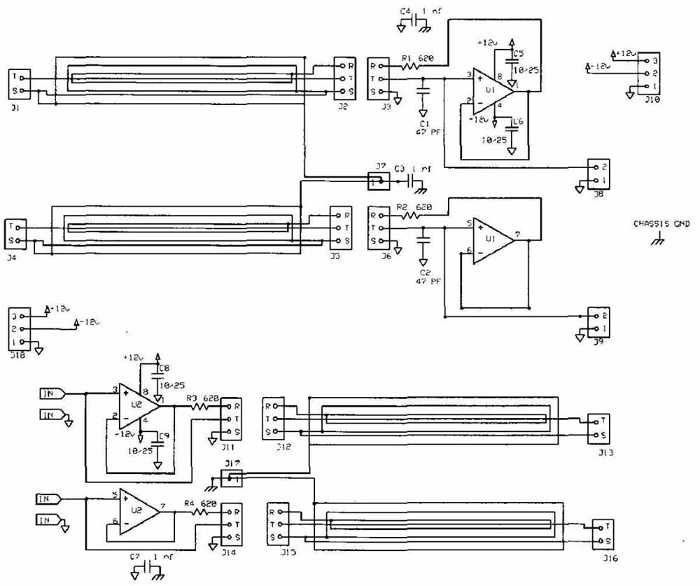
Above: Fig. 1: Input and output shield drivers.
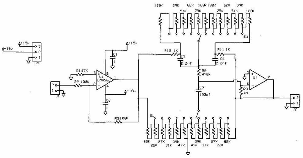
Above: Fig. 2: Tone control circuit.
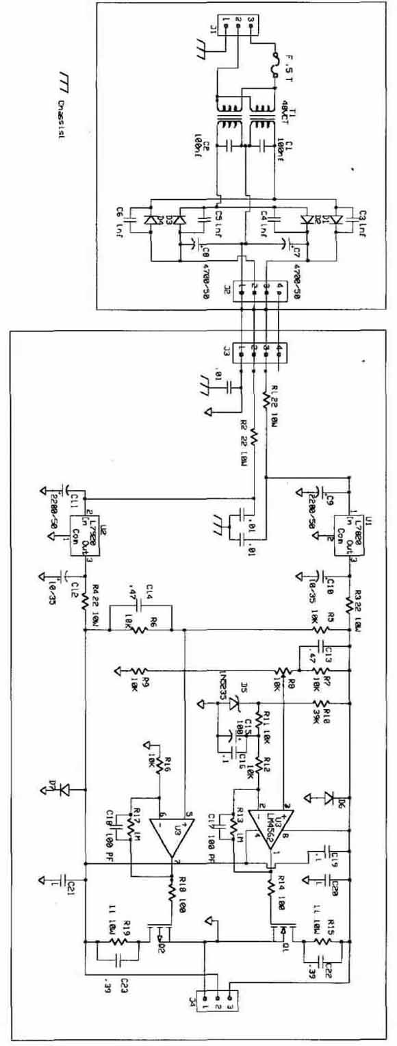
Above: Fig. 3: Power supply regulator.
For the RCA connectors I tried three different types: all gold-plated audiophile types. You can pick your favorite here; just be sure it can handle a large diameter cable.
To construct some of the cables I used silver or silver-plated stranded Teflon insulated wire. For others I cheated and started with a piece of shielded audio cable cut from a decent premade RCA- RCA cord. The quality of the signal conductors does affect the final product. I have found that thinner better metals do have an advantage.
The shield braid used to be a common item. I could only find it in the larger size at McMaster Carr (part #5537K26 and 5537K14).
I used a third-hand jig to hold the connector and cable while soldering. I did not want any motion while the solder cooled because theory suggests that this promotes crystal formation.
After soldering the RCA end center silver 22-gauge conductor, I slipped over ½” heat shrink, cooked it, and then placed the rear cover. Next to go on was a thin shield braid that did not quite extend into the cover. I added a small jumper connected to this at the non RCA end. Tape kept it in place so it would not short to the center conductor.
A layer of ½” heat shrink that did go into the cover was next. More thin braid went over this, but again not into the cover. The jumper went to the RCA end for the send cables, the far end for the others. I wrapped a silver or silver-plated insulated wire around this and soldered it to the shell terminal. If this is a send cable, you need to connect the jumper and a short bit of uninsulated wire. The next piece of ½” heat shrink covered this.
I connected the phone plug to the other end. I needed to cut the strain relief short and ream it a bit to fit the cable. The larger shield braid goes over the completed connectors, and then trimmed and soldered to the appropriate jumpers. A bit of tape held this in place and Techflex tubing in red or black covered the outer shield. This was held in place at each end by more ¾” heat shrink tubing that also covered the rear shells of the connectors.
It was easy to push the braid and Techflex over the cable, but the heat shrink sometimes was difficult. It was easier to push a stiff wire through the heat shrink and use it to pull the cable through. On long runs you can use a brass wire and solder it to the silver wire. After you clean the connectors with De-oxit, the cables are complete.
Of course, if you are using audio cable for the core, you can skip a step.
I positioned the send and receive modules so that two receive and one send fit on an Expresspcb mini-card. There is nothing special about the cards, which don’t handle high-quality signals. I did isolate their power supplies from the audio circuits by using two 10-ohm resistors for each card.
You can use the cards and cables as standalone devices. I used one as a guitar cable buffer, which resulted in noticeably better high end. I also chose to build these cards into my new preamp.
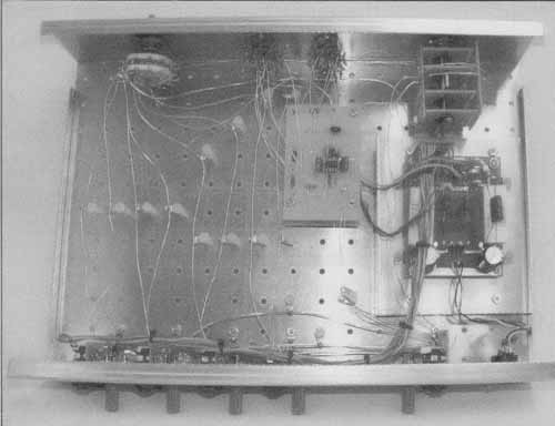
In my preamp the signal lead from each input card goes to a selector switch via a piece of un-insulated dead soft silver wire, which is attached to nylon standoffs to minimize vibration-induced signals. I used a 12-pole double throw (12PDT) rotary switch for the selector. It’s a military surplus silver-plated large diameter ceramic rotary switch. I treated the contacts with Deoxit. The signal return or “ground” leads from each input go directly to the output send buffer card, where I establish my common ground reference point. A better point would be at the return end of the attenuator, but I did not figure that out until I finished.
Above: Fig. 4: Power supply top input, middle after regulator, bottom after
shunt regulator.
The output of the selector switch goes to a stepped attenuator. I had a leftover 24P4T Alps switch made for this purpose. I made PC cards to hold 1206 size 1/3W surface mount resistors, a size that can be soldered without magnification. I used 94 of the IRC PFC-W1206LF- 03-XXXX-B tantalum nitride 0.1% 25 ppm/C non-magnetic resistors to make the attenuator. I selected these because as high-end audio parts go, these are reasonably priced. I like the 1206 size because they are easier to solder. My attenuator has 10K input impedance and varies on the output. I learned from my previous “preamp” that most of my listening is done about 20dB down, so I jiggled my step sizes to have more resolution in that range.
After doing all this, I realized next time I will buy an attenuator already assembled, which is easier, works the same or a bit better, and actually costs less! The output of the attenuator originally went to the output card. An outboard ±36V DC power supply fed an internal shunt regulator to power the buffer cards. A direct run went to each card establishing a second common ground at the power supply, reducing any mutual impedance signals. A single connection coupled the output card to the power supply.
I used a shunt regulator modified to have more AC response; in this use with a known load and good shielding, RFI should not be a problem. Measurements showed the shunt had more than 20dB additional noise attenuation than with just the regulator. The power transformer, bridge rectifier, and first filter caps are in a small steel box 6’ away from the rest of the gear.
The downside of this shunt regulator is that it draws a higher startup current than a series regulator. So it’s best to use a time delay fuse.
TONE CONTROL CIRCUIT
You need a tone control to complete the preamp. The tone control was actually the trickiest part. In the late 70s, when mixing boards were becoming common, the tone control issue re-emerged. Initially it was more a question of how to make an effective low-cost tone control, but once the knockout punch was published by P. J. Baxandall in 1952, there was only quibbling about variations. By the 70s, with cheap parts, ICs, and biquad or other new filter topologies, the issue became how should the knob change the sound?
The problem now was not so much designing the circuit, but getting the “feel” right. When you give the bass knob a quarter turn, you expect certain changes. More or less change is awkward. As loudspeakers improved, the apparent effect of the control was greater.
What was once a fine treble control now is too harsh on a modern tweeter. A bass control that was fine on a tight suspension woofer becomes tabby on many around today.
The standard Baxandall circuit for a two-knob tone control is three capacitors, two variable resistors, and a few fixed resistors. To get smooth action the controls needed to be linear. A later takeoff used log pots and different capacitor values to get a better feel. The disadvantage of the Baxandall was that it required a center-tapped pot and a pentode to provide the negative feed back.

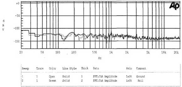
Above: Fig. 5: Not so good DIY cable top, bottom preamp and cables. Note
HF rolloff and noise level hides THD inherent in test equipment.
Above: Fig. 6: Tone control curves.
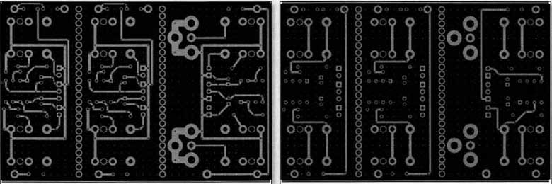
Above: Fig. 7: Bottom PC layout.
Above: Fig. 8: Top copper layer.
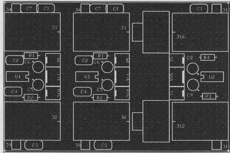
Above: Fig. 9: PC cards silkscreen layer.
Today negative feedback is not a novel application. Stereo, however, has placed a few more demands on a tone control. A stereo potentiometer with good tracking, high resistance, and a center tap is really hard to find. Using switches and resistors gives me a great advantage. I can select the resistor values to give me logarithmic control and still use matching capacitors.
I used regular carbon film resistors for the control switches. Once my crew and I have used the control a bit, it will be practical to home in on the useful range and pick exact values. Then I will change to better switches and resistors. The circuit I used is deliberately very close to the original design and is shown in Fig. 2.
I used an LM4562 op amp, silver mica capacitors, and precision resistors for the tone control cards because I need to only change the switches later. The PC cards for the tone control are stacked on top of each other to maintain a similar level of wire lead path length and vibration level.
To keep out vibration I made some feet out of two aluminum discs and two different foam rubbers. Both are quite soft—40 00 durometer for one and a bit firmer for the other. The impedance mismatch helps to reduce vibration. I mounted the feet to a sub-plate ½” deep and added a bit of foam to seal this chamber to the chassis. I used 6-32 screws with pieces of auto store ½” ID rubber hose as flexible spacers to attach the plate.
I punched a 1” matrix of holes in the bottom of the chassis to make mounting components easy. The sub-plate now sealed the chassis. Inside was silica gel to keep moisture down and as a bonus the loose fill absorbs vibrations. The final environmental control was a strip of silver tarnish paper to remove sulfur and keep the silver shiny new.
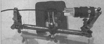
PHOTO 1: Helping hand holding parts to be soldered.
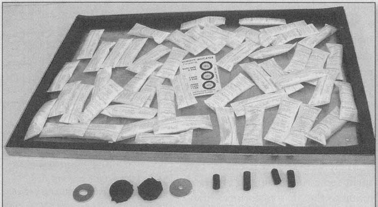
PHOTO 3: Bottom pan with gasket and silica gel, foot parts, and rubber tubing
spacers.
RESULTS
Measurements of the preamp showed that it was actually better than one web DIY cable design. It was as good as a jumper cable across the test equipment for most of the audio band. There was a higher level of 60Hz hum than from a short jumper. This was interesting because the fundamental of the power supply was 120Hz, which was 105dB down at the output of the regulator. So I suspect this is due to the longer cables and greater area in the possible magnetic field.
When I first turned on the new pre amp, I heard a noticeable buzz in the sound. Then I realized the preamp was set to tuner for a sports-talk station. The buzz was just normal for them! On everything else the system seems dead quiet.
So it’s possible to do better than a “straight wire with gain.” You can have less noise, lower losses, higher output current, selection ability, gain, and tone controls.
