In the first three parts of this series, I looked at why you need to clean up the AC line, three passive ways to do it, and one method reusing
a larger power amplifier. In part 4, I look at building smaller amps and using them to produce clean AC power.
I start with a design value of 250W of AC power for a simpler version of an AC 120V supply. I picked this because it’s enough to power all of my sources and preamplifier. In addition, transformers of this size are readily available.
For this design you will need an amp that can produce a lot of current because as the voltage is stepped up, the current is stepped down. The amp should be efficient to minimize wasted power.
HEATSINK APPROACH
The first issue that jumps to my mind with any high power amp is heatsinking. I can find power transistors rated for 200W if the actual transistor die is kept at 25° C. The power handling goes to zero watts at a temperature of 150° C.
A quick catalog search shows I can buy a Wakefield heatsink 423K for about $15 to $20. This has a temperature rise of 47° while dissipating SOW. I know from experience that I like to limit my heatsink temperature to a 35° rise. That means that a well-designed material- efficient heatsink will allow a free-air dissipation of 37W.
In the worst-case short circuit I expect my power transistors to dissipate the entire power supply, which can be as high as 600W. For normal use I cannot calculate the exact value because I don’t control the reactance of the load. I estimate it to be 200W. If I design my heatsink to handle 200W normal load and add a fan to kick in when the temperature rises, I can get the best of both. A system that is quiet in normal use and is less likely to fail when I am being stupid.
Six of the 423K heatsinks will do. The cost is almost reasonable. I am now about to reveal one of the great secrets of saving money on heatsinks. The loose of pocket guide should read no further.
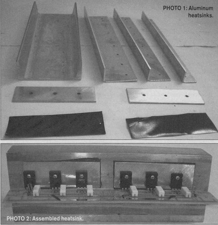
If you take your shopping cart from the heatsink aisle to the structural aluminum aisle, you will find some great bargains. I can buy 8’ of 4” x 2” U channel for under $50! If you choose to add fins, add two 1/8” thick angles (1 x 1.5 and 2 x 1.5) and keep the bill under $100. All of this gives you 8’ of heatsink! Even better is when you find some used scrap! I got a giant pile of 5” channel for the asking.
You will need to cut the aluminum, clean it, paint it, and bolt it all together. To cut the aluminum you can use a hacksaw, a saber saw with a metal cut ting bit, a band saw, a chop saw, or, my favorite, a powered miter box! I use a standard DeWalt saw with a 12” blade made for cutting aluminum. I bought them both at Home Depot. (If you don’t wear gloves, eye and ear protection while cutting the aluminum, please consider another hobby.)
To prep for paint you can sand it all or use a cleaning solution that contains lye. You used to be able to buy lye in small quantities, but it’s usually not available that way anymore. You might read the labels of other cleaners or just use a bit of Drano crystals. Wear gloves and eye protection, using only enough to quickly wet the aluminum. You will see it almost instantly become bright and shiny. Rinse it off immediately and dry it. You have about 15 minutes from when you clean it until paint won’t stick to it. As soon as it’s dry; paint it with a thin coat of black paint.
If you drill a few holes, you can bolt the angles to the channel for additional radiating surface area. This heatsink is not as efficient per volume as a commercial unit, but on a watt per dollar basis it’s unbeatable.
I attached resistors to my structural aluminum heatsink and measured the temperature rise. With an input of 110W a 14” length of 5” channel with out any extra fins rose by 65° for a rating of 0.6W per degree! Adding a few fins gives me a heatsink for this amp at the bargain price of less than $15.
If you wish to save even more, you might try a visit to an aluminum distributor, which often has a room with scrap for sale to hobbyists; sometimes you may even find actual heatsink leftovers. My local distributor charges me 85 cents per pound for his leftovers. At those prices this becomes a $4.04 heatsink!
HEAT LOADS
The next issue is to actually get the heat into the sink. For small heat loads I like to use the mica washers made for the purpose with a very small amount of heatsink grease. There is a loss of about one-half of a degree per watt for using the insulating washer.
In this case I mount my output transistors directly to an aluminum heat spreader and reduce my insulator heat losses. A small bit of grease helps here also. The spreaders get the most heat possible out of the transistor and then spread this over a larger area in order to reduce the loss through the insulator. This is the same effect as paralleling resistors. Note: The heat spreaders will be at the same voltage as the transistors’ cases.
To insulate the spreaders you can buy thermally conducting rubber sheets made for this purpose. See the black sheets below the heat spreaders in Photo 1. Digi-key’s BER232 is fine for this use. If you wish to save a bit you can even try greased paper!
The rubber sheets are fragile, so you must be sure you have no sharp burrs on your heatsink or spreader that will punch through. I find sanding with 400 grit sandpaper cleans up the burrs. I then wash the material with dishwashing soap and water.
I use nylon standoffs 1/4 in diameter by 1/8” long in the mounting holes to keep the steel mounting screws insulated. I found the mounting holes in the power transistors were too small for the standard 6-32 machine screws, so I reamed the holes to fit. You may wish to use 4-40 hardware or go metric. After I had mounted everything, I let it sit over night and then checked for shorts with an ohmmeter (Photo 2).
You certainly can try another approach to heatsinking. The nice thing is that if you are conservative in your electrical design, a small increase in the temperature of the heatsink causes a greater increase in its efficiency. Painting the heatsink black almost doubles the power dissipation for a convection-cooled unit. Fan cooling is even better.
TRANSISTOR SELECTION
The next design issue is how many out put transistors are required. I like a safety margin on the ratings of my transistors, so at a heatsink temperature of 60° my 200W transistors are good for 150W, and allowing a 1.67 margin still leaves 90W per transistor. That would give die to heatsink losses of another 40 to 50°, which would reduce the power dissipation to 80W (not a bad first guess).
At a worst-case dissipation of 600W, seven and a half output transistors would be fine. I could use four per amplifier module but I will round it up to six, five not really being a choice. A handy double-check on power dissipation is the rule of thumb 30W per T0220 case and 60W for T03 or T0264 cases.
I had a number of leftover Hammond 182T12 transformers with two 12V 12.5A secondary windings. If I use these to make a power supply for my high current amp, I can get a target voltage of 16.5V. This could range from 14.75 to 18.1V (diode drops included). At 14.75V, 300W out would require 20A, so I can use two of these transformers either together or as two separate supplies.
PHOTO 2: Assembled heatsinks.
I would like to use the cheapest commodity transistors I can for the output stage. Unfortunately, when my associate Billy did that he found out that batch- to-batch the transistors had quite different parameters. After many blown up amps, he went to a better grade. So you can learn from the mistakes of others.
About the best bipolar audio power amplifier output transistors are the ON Semiconductor MJL4281A/4302As. These are a bit pricey, so I drop a step to the MJL1302/3281, which costs one- third less at one-eighth less power. They have enough bandwidth to minimize oscillations. The betas are well matched between devices and are reasonably high, allowing an efficient design. I have found it’s still best to beta-match sets for the out put. For some reason I find the PNP transistors are pickier.
A simple beta test is to use a 12V battery, an ammeter, and a 330 ½ W resistor. Clamp the transistor to a heatsink and measure the current drawn when you touch the resistor to the base. The transistor will heat up and increase the beta so you will need to get a feel for when to read the meter. The faster you get your reading the better. Expect to see currents from 1 to 5A. I line up the transistors from low to high and then use three in a row for my output stages.
POWER SUPPLY
To keep the design efficient I use one set of supply rails for the output stage and a second higher voltage set for the drivers and gain stages. The higher voltage rails need not have the same current capacity as the output rails.
To get a second higher voltage rail, I could use another transformer. Instead, I wound a few extra turns on my transformer. When I powered up the transformer I found that I get 0.33V from a single turn on the output. I wound two pairs of 12 turns using 18-gauge magnet wire. This gave me two extra secondary windings that I then placed in series with the original secondary windings to get the higher rail voltages (Fig. 1).
The rest of the power supply is plain vanilla. I used high-current low-loss Schottky diodes for rectifiers and big capacitors to keep the ripple down. Multiple capacitors on the high cur rent rail are an effective way to get enough filtering.
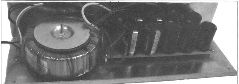
I selected the values for 5% ripple at full load. It turns out that 39000uF at 25V was the biggest low-cost capacitor, and because the audio does not go through these capacitors I went cheap. I used 22000uF at 35V for the higher rail voltages. I stayed with the same diodes even though the current requirements were much less ( Fig. 2). 1 built this sup ply on a folded piece of 1/8” aluminum and used the chassis for the heatsink (Photo 3).
There is still some ripple on the rails even with lots of capacitance. This ripple may show up as a slowly varying change in the output voltage. This is due to the minor difference in the AC line frequency and the oscillator. For example, if the oscillator is actually 60.05Hz, then you would see the effect of the power supply ripple over a 20-second cycle in the output voltage.
I could use an electronic regulator to fix this. That may reduce the efficiency, so you must allow for a 10% low line condition in addition to the ripple when you calculate the available voltage from the supply. So 12V AC would be come 17V DC less 10% for low line, less ripple of 1 .2V and a diode drop. Thus I can expect a rail voltage of 13.6V. You will have some additional losses from the transistors and the emitter resistors. These should be about 1.2V. An output voltage of 12.4V peak would allow an AC RMS voltage of 8.8V. Thus you could expect efficiency to be no greater than 54%!
A bridged amplifier configuration helps some of these problems. It makes it easy to use two power supplies. Each supply now needs to provide only one half of the current because you now have twice the voltage available. This also lowers the ripple. You now have twice the output transistors, so fewer heat concerns. You can use a 12 or 15V to 120V transformer, which is a bit more common. Your line voltage and desire for efficiency should shape your choice.
Keep in mind these transformers are designed for stepdown use, not step- up. A cheaply made or well-designed transformer (depends on your point of view) may have some characteristics that become a problem when you reverse it. The typical issue is at startup if the transformer saturates and how this affects the rest of the circuitry. To prevent this, place a 2-ohm resistor in series with the output; after startup this is switched out.
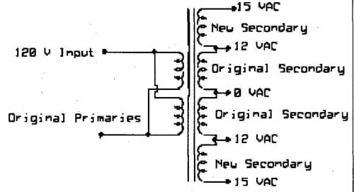
Above: Fig. 1: Modified transformer.
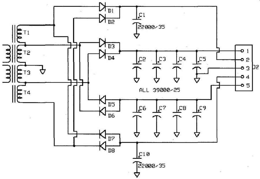
Above: Fig. 2: Power supply circuit.
DESIGN TWEAKS
Now that you have the power stages, you should look at driving them. The two power rail system allows a higher voltage for the stages that drive the output stage. That way there is a minimum of excess voltage across the output transistors. When you produce 250W at 15V to drive the transformer, you require 16.7A RMS. That is a peak current of 24A. The output transistors have a specified minimum beta of 45 at 10A.
Using a safety factor, I will design for a gain of 30. Therefore, you will need to provide 800mA of current to drive the output. The driver transistor will need to dissipate a worst-case heat load of 25V high rail voltage at 800mA or 20W. This, of course, would only be if an output failed. Under normal use it would be closer to 2W. You already have a giant heatsink, so mounting this transistor to the heatsink should allow it to survive even under failure conditions.
This driver transistor would require a current of about 15mA to drive it. This is a bit more than I would like to see, so I will use a Darlington configuration here.
You could use a standard Darlington driver for this design, but at only 24V of supply rail a double diode drop loses 5% of the voltage. That is why I chose to use a PNP/NPN conjugate Darling- ton. There is a cost to using so much amplification, though. That is the risk of oscillation. Adding emitter resistors limits the gain of each stage reducing the risk of oscillation. Good layout is still important.
In theory this amp could run as a class B design. In a class B there is not steady current in the output transistors when the output is zero volts. For audio use these designs are biased so there is always some current flowing from the positive rail to the negative rail through the outputs. This class AB design lowers distortion.
Here you would have a dead zone of four base emitter drops if you did not use a bias circuit. I have found that when the voltage amp tries to compensate for this, oscillation results, so I have included a bias circuit. This is set for just enough voltage across it to start some current flowing through the outputs. I have used the same transistor as the driver type to try for some thermal matching.
Even with the input to the Darling- ton running cold there is still significant mistracking. This means the bias must be adjusted after the circuit is warmed up and at operating temperature. You can adjust the bias by monitoring the input current and turning it up until you see the current rise and then backing it off a hair to stay as close to class B as you can. Remember there are two amplifiers and two bias adjustments.
The driver transistors still need a voltage source. I decided to use an op amp for the front end. It’s a simple way to get a lot of gain in a few parts. To keep it stable I use an external compensation network at the op amp. The particular op amp can swing more positive than negative, which is why I can connect it above the center of the bias point. I picked an LM2O1 because it can run from 22V rails giving the headroom you need to drive the other stages ( Fig. 3).
The oscillator to drive these amplifiers can be any good stable 60Hz oscillator. I used the transversal filter oscillator from part 3.
There is one other small circuit I used to build this version of the clean AC power supply—the fan controller. I used two small 12V fans with this circuit. The LM35 temperature sensor gives a very precise output voltage related to temperature. This is compared to a reference voltage provided by R2 from the power supply.

Above: Fig. 3: Voltage source.
As the temperature rises, the op amp will turn on the fans. For my fans the transistor did not require a heatsink. The diodes allow the op amp to work close to the ground rail. If you use a true rail-to-rail op amp you can omit them (Photo 4).
You should mount the LM35 in a good place to sense the temperature. I super-glued it directly to an output transistor case. I then mounted the two fans between the two heatsinks, giving me a nice wind tunnel. The fans barely come on during normal use.
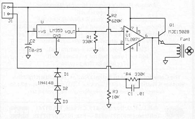
Above: Fig. 4: Fan-controlled ckt.
TESTING
The complete 120V AC supply is almost done. Two DC power supplies, one oscillator, two amps, a fan controller, and one step-up transformer. The oscillator drives the first amp, and the output of this amp drives the inverting input of the second amp. Both amps now drive the output transformer. The return path for each amplifier output is through the other, so a good ground connection between the two power supplies is quite important. If the power supplies are matched, you can also strap the output supply rails to each other ( Fig. 5).
You should test the circuits without a load through a current-limiting light- bulb box until you are sure it works. You will find the 2-ohm resistor is required at startup for most transformers. Check the oscillator for a good signal and then see whether both amps have a clean output without distortion, oscillation, or ripple.
Once the AC supply works during testing without feedback, connect the feedback. If it goes crazy, you most likely have the transformer providing 180-degree of phase shift. Just switch the leads to the feedback resistors. Now the output voltage will drop and you can reset the oscillator level for 120V.
Once everything checks out, try the circuit on something simple such as a few light bulbs. When you are confident that all works well, you can connect it to your system. There are two power switches: one turns on the input power to the circuit, the other bypasses the startup resistor. Turn the input switch on first, then the bypass switch. You may wish to have your equipment turned on before you engage the bypass switch to minimize current surges while your amplifier power supply capacitors charge. Another possibility is to use a relay to bypass the resistor.
I did not determine the output impedance of the finished product. If you want to increase the gain of the amps set by R19, decrease the 330K feedback resistors or both; you should be able to get a stiffer supply. This was not important for my use. If you decide to build a supply such as this, you will have a less than 50% efficient method of turning 120V/60hz into 120V/60Hz (Photo 5).
A better way may be to use a smaller amp in series with a moderately cleaned up AC line. This approach avoids rein venting the ally quite complicated, more of a “ you can do this better than the commercial product approach.”
You can use the same amps as used in the smaller supply, but add just a few more parts and get a regulated clean AC supply of 20A! I will look at that in part 5.
