This low-cost, high-performance hybrid unit, called the Nishiki amp, includes a tube driver stage and transistor output stage.
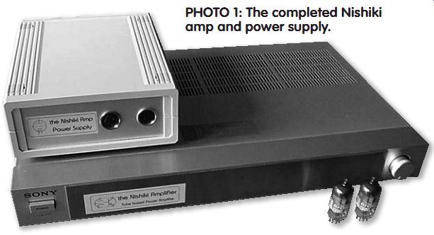
PHOTO 1: The completed Nishiki amp and power supply.
In my opinion a hybrid amplifier is in many ways the ideal amplifier-it combines sonically favorable tubes with modern semiconductors to drive low impedance loudspeakers.
My design goals of this amplifier project are low cost, low component count, high performance sound, good specs, and reliability and flexibility in the use of different components.
Using tubes, you are able to come up with a less complex design yielding low component count, rather low cost, exceptional sound, and good specs. How ever, if you choose to build an all-tubes based amplifier, it is almost mandatory to use an output transformer to drive the loudspeakers. This transformer will make the overall cost high, far too high for a project like this. So why not use modern semiconductors such as a power transistor instead of a high-cost trans former? This project can be divided into two parts-the driver stage and the power stage (aka current stage). The main part of this project is the current stage, which includes a circuit board. I mention a few tube/circuit possibilities for the driver stage; however, you could use other tube circuitry as well. The driver stage should be able to supply an output voltage of approximately 20V RMS into a load of 10k-O.
As with many of my other DIY projects, I chose a name for this design as well. Because the overall result is refined and colorful, I named it the Nishiki Amplifier (Photo 1).

FIGURE 1: Driver stage using the 5963/ECC82.
DRIVER INPUT STAGE
At the beginning of this project, I chose to use 5965 tubes. I had purchased several new 5965 RCAs a long time ago-for just 2 euros each-although I had never used this tube before in any of my projects. This 9-pin noval tube is quite interesting. Its pin setting con forms to the ECC83 family, its mu is as high as 47, and the plate resistance Rp is as low as an ECC82/6SN7 tube.
So with a single 5965, you could come up with a low component count input/ driver circuit.
In a previous hybrid amplifier, I used power MOSFETs and a paralleled 5687 tube as a driver, resulting in excellent sound and specs. However, in this new design I wanted to use power transistors instead of MOS FETs, so the driver stage needed re-designing.
At first I used the sections of the 5965 in parallel as a straightforward grounded cathode amplifier, resulting in a relative low output impedance of about 3k. With the first prototype, I noticed high distortion figures-the Hewlett-Packard distortion analyzer showed up to 3% distortion at full swing with load. I assume the drive signal is stressed too much by the relative low impedance transistor output circuit. These figures don't reveal every thing about the sound quality, but this is unacceptable. Distortion was mainly second harmonics.
I tried a combination of a common and proven grounded cathode amplifier with a direct-coupled cathode follower (aka compound amplifier); in this way gain and low impedance are combined using one single tube (Fig. 1).
The result was very promising. The distortion measurement in the proto type was as low as 0.35% at 1W with no overall feedback. This is a very acceptable figure because frequency range measured far above 100kHz and square waves looked just great. This would be the circuit to try.
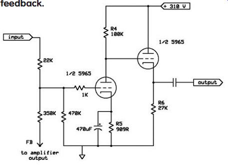
FIGURE 2: Driver stage using the 5965 and 10dB feedback.
Measuring the amplifier using this tube and the transistor output stage, I noticed that the distortion progressively increased with the output power.
Lowering the anode resistor to 33k and readjusting the bias voltage didn't improve the situation-it became worse.
Switching tubes from left to right and vice versa or installing brand new ones didn't change the situation. An attempt to replace the 27k cathode resistor with a transistor-based current source didn't help either; improvement was there but still did not convince me. Using +400V DC and a 68k resistor made the best out of a worse case, but distortion was still too high. The 5965 seemed not to be the perfect choice in this application/design, also because the overall sound of the amp using this tube is very disappointing.
In Fig. 2 you see how the 5965 is used with 10dB feedback. Distortion and sensitivity are acceptable now. In case you prefer the 5965 over the ECC82 and ECC88, I believe you should employ the feedback option.
---------------------
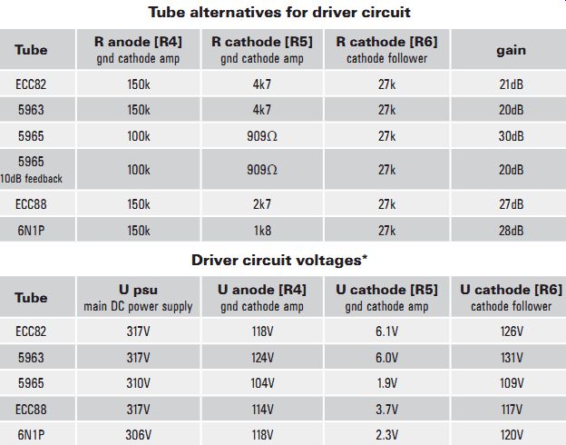
TABLE 1: Component values and voltages circuit alternatives
Tube alternatives for driver circuit
Driver circuit voltages*
*Notice: actual measured values related to ground, all measurements approximate values; depends on varieties in tubes and power supply components.
----------------------
In this circuit with feedback the amount of feedback depends also on the output impedance of the preamp which is used, because it is in series with the 22k. Unfortunately, I don't have any values for different impedances. The value of 350k that is given for approximately 10dB feedback refers to a low output impedance preamp of approximately 600-O or less.
I also tested the ECC82 and the ECC88, with which I am familiar. After some fine-tuning trying different values for anode and cathode resistors, I noticed already that with these tubes the amplifier yields much lower distortion figures at all levels. The ECC88 showed its quality-at 60W output I measured only a 0.5% distortion. You might like to check out the section specifications for the overall results.
I used several driver tubes in the prototype and I have included a list with tubes and their specific component values. I recommend you start the project with an ECC82, which will give the best balance in specs and sound. Finally, I used a 5963 tube, which a friend gave to me to experiment with; it is a computer tube and an ECC82 lookalike.
First try the ECC82 and then the ECC88, but just compare the sound, not the specs. It is interesting how the over all sound and character of the amplifier changes with different driver tubes. You can easily make changes-just one resistor per channel and rewire the heater wire. I'm undecided about which is my favorite; I can live with both of them, but I believe the ECC82 gives a more balanced musical sound and the ECC88 a more technical loudness curved sound.
I used a Sylvania 6189 for the ECC82 and an E88CC by JJ Electronic for the ECC88. I also tested the Russian 6N1P, whose sonic behavior, I believe, is a combination of the ECC82 and ECC88.
The 6SN7, which equals the ECC82 in almost every aspect, would be a good choice for this project; however, I didn't try this tube, which uses an 8 pin octal socket. A compound circuit using the ECL82 tube, which contains a high mu tri ode section and a power pentode section, would also be an interesting approach.
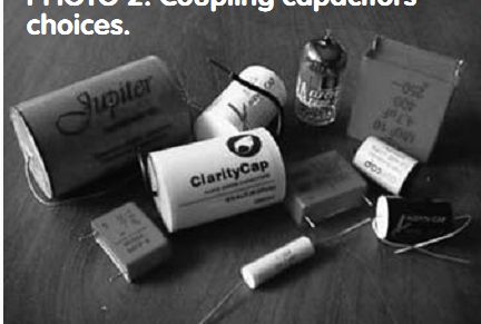
PHOTO 2: Coupling capacitors choices.
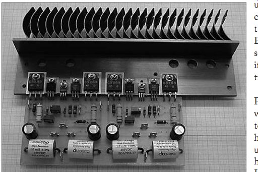
PHOTO 3: Prototype circuit board using an original Sony heatsink.
Because of the relative low input impedance of approximately 10k of the transistor power stage, the coupling capacitors should be at least 4.7µF. I believe the low cutoff frequency of the amplifier should be around 3Hz.
With a 1µF cutoff frequency, the value is about 15Hz, which I believe is too high.
In the prototype I used mainly a 1µF and changed it later to the higher value.
For a coupling cap, I chose an audio grade ClarityCap capacitor by ICW. B&W is using ClarityCaps in its prestigious Nautilus series. The used SA type produces very good results and is rather low priced compared to other audio-grade capacitors. You might wish to check out e-speakers.com for pricing.
The ClarityCap capacitors are hand wound using a 10µm (630V DC) rated polypropylene film. Following a special heat treatment cycle, insulated copper terminals are hand-soldered to give the best possible connection. The inherently low dissipation and dielectric absorption factors of polypropylene allied with excellent mechanical stability results in an extremely detailed sonic performance.
The construction also results in a low self-inductance and ESR; the devices are highly stable with regard to temperature and frequency.
If you would like to keep the amplifier to a minimum cost, you should try an industrial-type film capacitor, such as the Epcos B32524 series, which were once known as Siemens. The capacitor is 4.7µF rated at 250V DC and is available at Farnell.com (order code 400-2179) and priced at only 1.40 Euro each. Though I believe it's worthwhile to invest a little more, with the ClarityCap the overall performance such as soundstage and resolution will improve.
But again, I believe this Epcos capacitor along with the Russian 6N1P tube will do just fine! Of course, you are free to choose any coupling capacitor you like, but keep in mind the minimal DC voltage is 400V DC; you could also use a 250V DC.
If you want to give the amplifier an exclusive (and far more expensive) look, you could use Jupiter Beeswax paper coupling capacitors, which are large and expensive and extraordinary in design.
Because these capacitors use beeswax, you can't operate them above 43° C (!), and they don't come cheap. The four coupling capacitors together are more expensive than the basic amplifier itself.
List price for a 2.2µF (which was used for evaluation) is about $30 US each.
Again, if you just want to enjoy your CD selection, you should use the 6N1P/ Epcos duo.
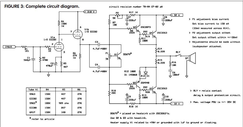
FIGURE 3: Complete circuit diagram.
OUTPUT STAGE
For the output stage you could use transistors or MOSFETs. In a former project I used so-called IGBTs, but these are out-of-production now and need a special design approach so are not very good choices. In hybrid projects I have used power MOSFETs for the current output stage and noticed that the 2SK1058 and BUZ900 families give different sonic results. Both are expensive if you compare them to power transistors.
Some time ago I repaired a Proton D1200 power amplifier, which uses eight power transistors per channel, and because I had some left over I decided to use them. The Proton uses the high performance multi-emitter LAPT devices manufactured by Sanken. For the output stage I chose a so-called Quasi-Complementary Output Stage (Fig. 3) over other configurations, not the more common complementary emitter follower.
I noticed that solid-state designs using two identical output devices (N and N) sounded great. Just a coincidence? I re call a contest in the Japanese MJ magazine in which the first-prize winner was a low-powered transistor amplifier, using an N - N output configuration. In a former project I used the LM3875 power device with its N-N output configuration in a two-way active loudspeaker with great success.
Amplifier manufacturer Naim uses this topology in all of its designs. To quote Julian Vereker of Naim Audio: "NPN and PNP power transistors are only really as equivalent as a man and a woman of the same weight and height." In the early years complementary P channel transistors were expensive and did not equal the characteristics of an N channel device. These days, complementary transistors are very common, though I believe the N-only output stage is the better choice and will give better sonic results.
As mentioned, I chose the widely used high-performance multi-emitter LAPT power devices by Sanken, the 2SC3263.
I bought original devices for less than 4 euros each. However, you could choose the 2SC3519/A, 2SC5200, MJL3281A, or MJ15003. The 2SC3263, 2SC3519/ A, and the 2SC3284 are identical de vices in TO3-P packages, all made by Sanken, with only the voltage ratings different. I have used the 2SC5200 with great success.
For the driver devices, I chose audio grade driver transistors by Toshiba, the 2SA940 and the 2SC2073, which sell for only about 1.50 Euro each and are widely used in many designs. You could also use the MJE15030 and MJE15031, which should work just fine, though I didn't try these.
I added a 392-O resistor in series with the base of the driver transistor to enhance stability. I found that using a low Zo wave generator as driver source-in stead of the tube driver circuit-caused the output stage to oscillate. With the 392-O resistor, the current section was stable under all circumstances, so I also placed small resistors on the order of 2.2-O in series with the bases of the out put devices.
The drivers should be using some kind of heatsink; the circuit board is made in such a way that the drivers are mounted on the main heatsink. If you don't use the circuit board, you should give them each a small heatsink, such as a 6 to 8° C/W type.
Mount all transistors so they are electrically isolated from the main heat sink and from each other; use dedicated isolation pads and isolated rings.
I have good results with the so-called SIL_PAD 2000 insulators. I added the Baxandall diode D1 to produce a better output symmetry. I chose the 1N5060, but you could use either a 1N4001 or 1N4148.
For thermal compensation of the out put transistors, I used a Darlington transistor (Q1), which you should mount near the output devices on the main heatsink.
With this little circuit, the amplifier is very stable at all levels.
Bias current of the output stage is set to 140mA using P1. With slider P1 to the collector of Q1, you will achieve minimal bias. You should measure about 30mV across one of the emitter resistors.
Using P2, you can set the DC output voltage of the amplifier to zero (any value within + and - 50mV is acceptable). Make adjustments without any load attached and repeat them some time after the amplifier is switched on.
Distortion of the transistor output circuit is not measurable with my existing equipment. The tube driver circuit causes the distortion of the overall amplifier. I added the two RC combinations (R17/C7 and R18/C9) because without these I noticed some hum at the output; with these extra filters it is really quiet. R1 and C1 form a low-pass filter section, which gives the amplifier rolloff at 105kHz (at -1dB) and makes the amplifier more reliable and less critical.
To make this amplifier design more versatile, you might add a 4µH coil in series with the output of the amplifier.
This output conductor could be 16 turns of 0.75mm enameled copper wire wound on a 6.3mm drill bit. A 15O 2W resistor should be located within the coil.
You should consider the use of a DC protection and power-up circuit. Several manufacturers offer kits.
The amplifier design presented here exhibits no problems at power-up or switch off because of the cathode follower. At power-up the cathode starts at 0V and increases to approximately +120V DC.
If you choose a kit, you might consider the Velleman K4700 Speaker Protection Kit, which sells for only 20 Euros. The kit provides a 6-second delay after switch-on to avoid any thump as the amp comes up and, as soon as the amplifier is switched off, it disconnects the speakers to prevent any switch-off thump. It also provides DC protection by disconnecting the speakers if DC is more than about ±700mV. This kit uses its own mains transformer. The delay time of the Velleman kit is increased to 12 seconds by changing C11 to 470µF.
CIRCUIT BOARD
You could hard-wire the tube driver stage using a little tagboard; a printed circuit board for the transistor power output section should be mandatory, in terms of reliability. The prototype stereo circuit board shows a section for the coupling capacitors, but there are so many different shapes and sizes the final board is made without any space for the coupling capacitors. The final circuit board is intended for one channel only (Fig. 4).
For local bypass, I added capacitors C7/ C8/C9/C10 to the circuit board. Space for these capacitors is limited, so use the 10mm or less in diameter types, which will fit nicely.
The heatsink I used was taken from a 20-year-old amplifier. In fact, you can use almost any heatsink provided it is not too small, a 0.7 K/W would be a good choice.
Bias current is limited for this Sony heat sink to 130mA [28mV measured across an emitter resistor], to reduce heat dissipation.
The original layout of this circuit board is available to you. Please install the so called Sprint Layout Viewer on your computer. You can find this program on my website. Using this Viewer, you can view and print the original circuit board file.
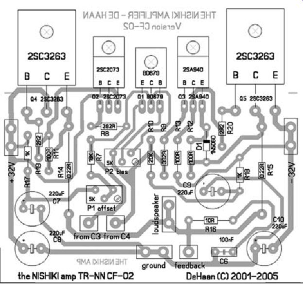
FIGURE 4: Circuit board layouts.
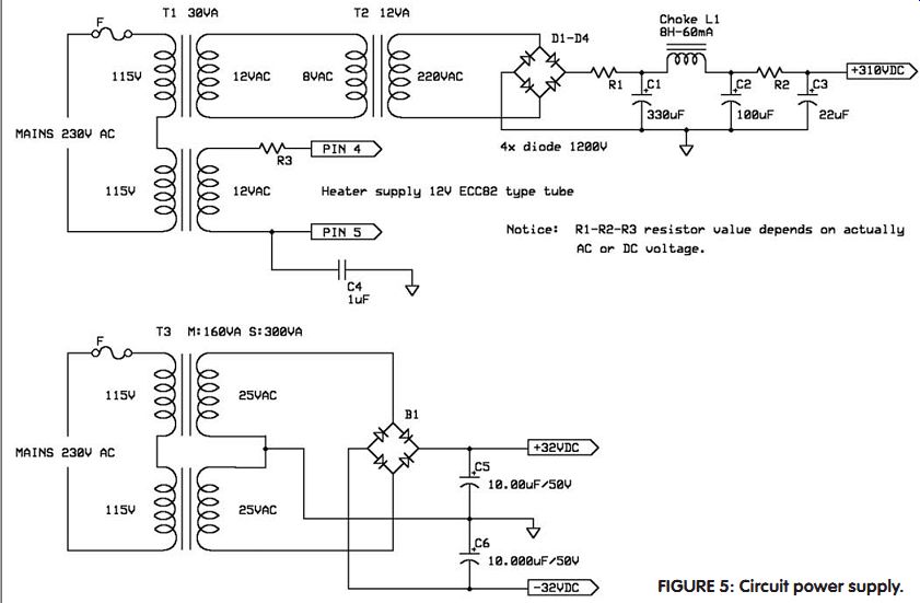
FIGURE 5: Circuit power supply.
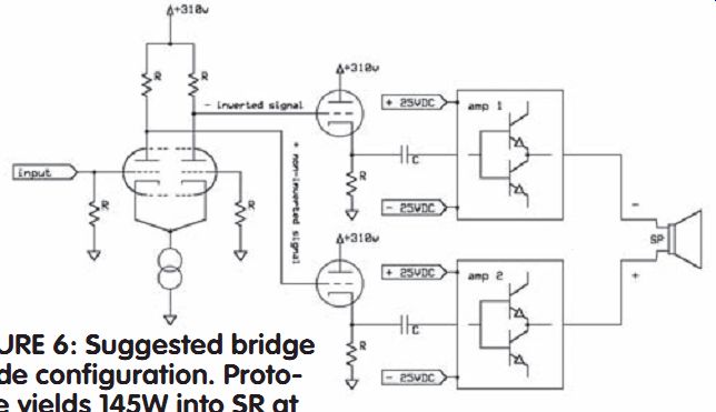
FIGURE 6: Suggested bridge mode configuration. Proto type yields 145W into
SR at 0.7% distortion.
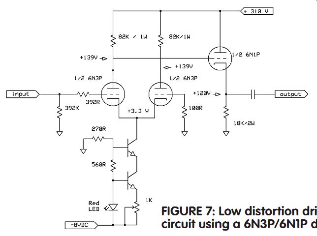
FIGURE 7: Low distortion driver circuit using a 6N3P/6N1P duo.
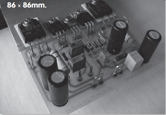
PHOTO 4: Mono circuit board measures 86 × 86mm.
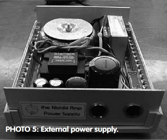
PHOTO 5: External power supply.
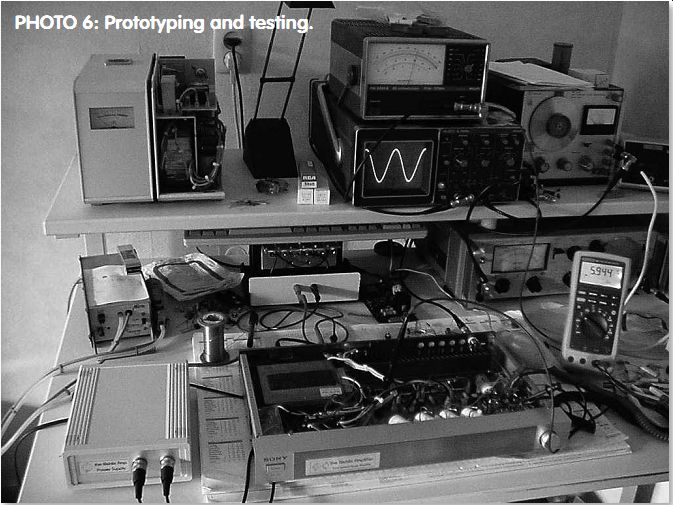
PHOTO 6: Prototyping and testing.
For those who are interested, a professional circuit board might be available.
Please inquire at the above-mentioned website. For stereo you will need two boards.
POWER SUPPLY UNIT (PSU)
The driver circuit runs at +310V DC with a 6 or 12V as heater supply. The output power stage runs at ±34V DC, because of the original Sony mains transformer. At full load the DC voltage will be as low as ±30V DC using this mains transformer. I am not familiar with the power ratings of this transformer.
In case you need to buy a new mains transformer, purchase a 25V + 25V AC type. This voltage will yield ±32V DC, which is perfect. I would not recommend a higher voltage than approximately ±35V DC with ±40V DC as maximum, because power limitations and heat dissipation with a 4O load will be more critical, also because the driver is intended for ±32V DC use.
As heater voltage, I chose 12V instead of the more common 6.3V. The power supply circuit will make clear why this was done (Fig. 5). Two small mains transformers in cascade provide both the high voltage you need and the heater voltage. Of course, you could use a dedicated mains transformer intended for tube use.
The used mains transformers T1 and T2 are very common and rather inexpensive. I used an 8V transformer because it was available; a 9V works fine as well.
One section of transformer T1 is used for the high voltage section and the other section as heater supply. The 5965, the ECC82, and 5963 tubes use pins 4 and 5 for 12V heater voltage use. In case you use the ECC88 or the 6N1P, you can wire the two 6.3V heater wires of the tubes in series for 12V use. The heater is grounded by a 1µF capacitor; in this way the maximum cathode-heater voltage is not an issue and it's grounded. You might consider using a voltage resistor divider to relate the heater to, say, +70V instead of capacitor grounding.
For choke L1 you could use a Hammond 156L or a 156M type, which are only $11 US, or C1 and C2 could be lower in value.
R1 and R2 trim the DC high voltage to +310V. I used a link (0-Ohm) and a 1k resistor for R1 and for R2 with the tubes working.
This is also the case for R3, which trims the heater voltage to 12.6V. The power supply for the current transistor power stage is straightforward. I used one single bridge rectifier and two large capacitors.
It is up to you to decide whether to use one PSU for two channels or to give each amplifier its own power supply. For mono you use a 160VA transformer with 120VA as a minimum; for stereo a 300VA will do just fine.
THE REAL WORLD
I used a 20-year-old Sony TA-AX2 integrated amplifier as the "donor" for this project. I used the original enclosure, the original buffer capacitors, the heatsink, and the mains transformer from this 2 × 35W amplifier, thus reducing the cost of this project enormously.
I took out the original Sony circuit board, including the STK module, and used a stainless-steel plate to cover the original holes of the switches and potentiometers on the front. I left the volume potentiometer in place.
I bought this Sony amp for just 10 euros, not knowing whether it worked.
Because of its very slim design (height front is just 4.5cm, inside just 4cm), heater and high voltage supply need to be external.
You could use almost any secondhand amplifier. A 35 to 50W into 8-O amplifier will do, and will run at approximately the required ±32V DC. Amplifiers with higher output (into 8O) run at higher DC PSU voltages; this is overkill, because the driver stage has its limitations.
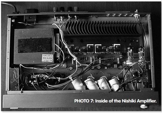
PHOTO 7: Inside of the Nishiki Amplifier.
FINAL WORD
During testing and prototyping, the amplifier turned out to be very reliable, though shorting the outputs is not recommended. The final amplifier has been running now for a long time without any problems. In spite of a design using a low component count, specs and sound are convincing.
I am very pleased with the final result.
By using an old amplifier for the enclosure and several main parts, I was able to keep overall costs to approximately 100 euros.
The sound is pleasant and entertaining, balance and soundstage are good. Voices and percussion, for example, are clear and never nasty or bright. It's fun to listen to, and the slim-line Sony enclosure looks good, too. Sometime during the prototyping, I used the 5965 and Audyn Cap Plus coupling capacitors and was very disappointed with the sound results-bright, no dynamics, no drive.
My DIY Dynaudio loudspeaker using the Esotar tweeter and the 17W75XL04 can sound great, but it can also sound not that pleasant and boring. My favorite Keith Jarrett music is a difficult job for many systems; to revolve all the magic it needs some attention. For example, in Ecstasy from Changeless there was simply no magic and it was not a pleasant listening experience. But by changing tubes and coupling capacitors, I ended with some thing I enjoyed.
Another example is "Young and Foolish" from Live at Village Vanguard by jazz pianist Brad Mehldau. Strange recording I thought, and it is. However, it contains many pleasant and good elements. Using the final configuration, I understand so much more of this live recording. It is a beautiful concert, and even at the end you hear the hammer mechanism very clearly without making a string sound.
I love music in this way! Also, Warren Bernhardt's Ain't Life Grand [DMP CD 478], track 2 + 8 shows what this amp is capable of.
The DAC used is based on a Crystal CS4329 evaluation board with an Arcam 170.3 CD transport using a balanced digital interlink connection. I employ Monster M1000MK3, IXOS 1004, and OCOS cables for the analog sources. The amplifier uses SED 6NIP tubes and ClarityCap coupling capacitors.
REFERENCES
1. John Linsley Hood, Valve & Transistor Audio Amplifiers (ISBN 0750633565).
2. Electronics World + WW magazine
[ UK], Nov. 1993, "Distortion in Power Amplifiers Chapter 4," by Douglas Self.
3. Velleman Kits, www.velleman.be.
4. ClarityCap capacitors, www.icwltd. co.uk and www.e-speakers.com.
5. ExpressSCH-all circuits/schematics drawn using this freeware program- www.expresspcb.com.
6. Sprint-Layout 4.0-Circuit board layout drawing program-www.abacom online.de.
e-mail: wim@wdehaan.demon.nl
website: http://www.wdehaan.demon.nl/
[Copying or distributing this article-such as posting on a website or online forum-is prohibited without written permission from author or publisher.]
-------------------
TABLE 2: Component List
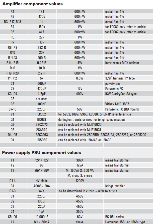
Amplifier component values
R1 1k1 600mW metal film 1% R2 470k 600mW metal film 1% R3, R17, R18 1k 600mW metal film 1% R4 150k 1W for ECC82 only, refer to article R5 4k7 600mW for ECC82 only, refer to article R6 27k 1W R7 18k 600mW metal film 1% R8, R9 392 R 600mW metal film 1% R10 20k 600mW metal film 1% R11-13 100 R 600mW metal film 1% R14, R15 0.22 R 4W Intertechnix MOX resistor R16 10 R 1W R19, R20 2.2 R 600mW metal film 1% P1, P2 5k 0.5W 3/8? trimmer TY type C1 560pF polystyrene C2 470µF 16V Panasonic FC C3, C4 4.7µF 400V ICW ClarityCap SA-type C5 not used C6 100nF Vishay MKP 1837 C7-10 220µF 50V Panasonic FC (OD 10mm) V1 ECC82 for 5963, 6189, 5965, ECC88, or 6N1P refer to article Q1 BD679 darlington transistor used for temp. compensation Q2 2SC2073 can be replaced with MJE15030 Q3 2SA940 can be replaced with MJE15031 Q4, Q5 2SC3263 can be replaced with 2SC3519, 2SC3519A, 2SC3284, or 2SC5200 D1 1N5060 can be replaced with 1N4148 or 1N4001
Power supply PSU component values
T1 12V + 12V 30VA mains transformer T2 8V 12VA mains transformer T3 25V + 25V M: 160VA S: 300 VA mains transformer M: mono S: stereo D1-4 HV diode 1200V B1 400V - 20A bridge rectifier R1-3 n/a to be determined in circuit - refer to article C1 220µF 450V C2 100µF 450V C3 22µF 450V C4 1µF 250V C5, C6 10,000µF 63V BC 051 series L1 8H - 60mA choke Hammond 156L or 156M type
---------------------
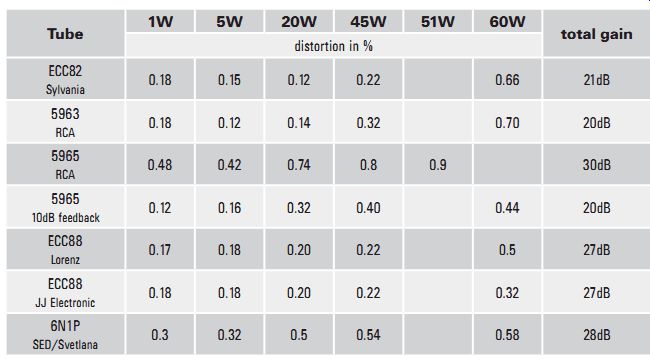
TABLE 3: Specifications
Distortion at 5-O load using original Sony mains transformers and 2× 6800UF PSU capacitors
Tube 1W 5W 20W 45W 51W 60W total gain distortion in % ECC82 Sylvania
0.18 0.15 0.12 0.22 0.66 21dB 5963 RCA
0.18 0.12 0.14 0.32 0.70 20dB 5965 RCA
0.48 0.42 0.74 0.8 0.9 30dB 5965 10dB feedback
0.12 0.16 0.32 0.40 0.44 20dB ECC88 Lorenz
0.17 0.18 0.20 0.22 0.5 27dB ECC88 JJ Electronic
0.18 0.18 0.20 0.22 0.32 27dB 6N1P SED/Svetlana
0.3 0.32 0.5 0.54 0.58 28dB
Frequency range: 10Hz - 105kHz at -1dB/1W
Damping: 10 Sensitivity: depends on tube, check out the Total Gain section
Equipment used:
Philips PM2454B AC millivoltmeter 10Hz - 12MHz Fluke 187 True RMS multimeter and Fluke 45 dual display multimeter Philips PM 5125 sine/square wave generator 10Hz - 1MHz Philips PM3211 oscilloscope 0 - 15MHz Hewlett-Packard 333A distortion analyzer
*Notice: at 60W output power the DC voltage of the power supply measures approximately ±30V DC.
-------------------
Also see: