This circuit for use with eye tubes eliminates variations.
Tuning eye, or indicator, tubes came into use before World War II to help tune radio receivers by indicating signal strength. This was helpful to reduce distortion and adjacent channel interference that would result if the radio were tuned too far from the center of the channel. The eye tubes were developed as a cheaper alternative to the needle movement meters. It was not until the 1960s that needle meters were made economically enough in Japan to displace indicator tubes.
During the decades from the 1930s to the 1960s, when tuning indicator tubes were in production, they found wide use in instrumentation as a low-cost alternative to the needle meter. Capacitor measurement bridges and tube testers were among the more common instruments making use of these inexpensive indicator tubes.

above: PHOTO 1
By the 1950s, indicator tube design had matured enough that good precision could be obtained for use as recording level meters in open-reel tape recorders. The most accurate indicator tubes were the European EM84/6FG6, EM87, and similar tubes, which indicate signal strength with two green fluorescent rectangles on the cylindrical wall of the tube. The green rectangles grow longitudinally, as the input signal grows more negative (Photo 1). At fill signal strength, the two rectangles meet in the center, forming a solid rectangle 1.5” long.
Figure 1 shows the internal arrangement of the EM84/6FG6 tubes, which were built with two integrated sections sharing a common cathode. One section is a small triode that amplifies the 0 to —24V input swing into a 0 to +250V swing that, in turn, drives the output deflection node. The plate of the triode has a 470k-ohm load to +250V and drives the deflection node on the other section to deflect the output beam on the fluorescent target painted on the side of the glass envelope. The 470k-ohm plate resistor sets the amplitude of this swing.

Above: Fig. 1: Standard wiring for EM84/6FG6 eye tube.

Above: Fig. 2: Transfer characteristics from input triode grid voltage to
target deflection for a Philips EM84/6F66 eye tube.
The supply voltage also affects the amplitude of the target deflection. Reducing B+ from 250V down to 200V to save wear on the phosphor also increases deflection. Some data sheets show curves for reduced supply operation.
The data sheets from various manufacturers show a carefully designed transfer curve from the input voltage at the grid of the internal triode to the size of the gap between the two glowing rectangles. This curve ( Fig. 2) follows a logarithmic characteristic very closely, covering 30dB of input voltage range. This accurate decibel response and the large bright display made these tubes suitable for use as fast, precise indicators of recording levels in tape recorders of the 1950s and 1960s. The logarithmic characteristic was also beneficial for use in radio tuning service, as it permitted extended indication of tuning at lower signal levels.
PRODUCING DECIBEL STEPS
When I discovered this logarithmic transfer curve, I was so impressed that I decided to test it. I built a circuit to feed a repetitive series of negative voltage steps staggered in dB increments to the input grid of the EM84. Figure 2 shows these steps in 6dB increments, as applied to the input of the EM84.
For this article, I chose three select able dB step settings of 3dB, 6dB, and 10dB. This sequence of fixed dB steps refreshes at a 250Hz rate and appears on the fluorescent target as a superposition of evenly spaced fluorescent bars of decreasing lengths.
You can make several adjustments to have this graduated pattern fill the fluorescent target exactly. First, you can adjust the 250V supply voltage or the value of the 470k pull-up resistor so that the two fluorescent bars meet exactly at the center when the maximum negative level of —22V or more is achieved and the input triode is cut off You can adjust the 470k pull-up from 200k to 1 Meg to make the rectangles overlap slightly in a bright line at the center, or you can leave a slight gap, to suit your preference. Compare the center overlap in Fig. 3b with the gap in Fig. 6b.

Above: Fig. 3: Exponential negative voltage step sequence in 6dB steps to
drive input triode grid of EM84. Each step has 50% of the voltage amplitude
of the previous step. Photo: EM84 6dB steps 30dB range.
You can also adjust the start of the deflection to open up the deflection pattern, so that the target is nearly completely blank when there is no input signal. A small adjustable DC offset voltage is added with pot U11 in Fig. 4 to the input drive to the grid, and is varied between —1V and +1V to nearly extinguish the minimum deflection pattern when there is no input signal.
The last adjustment to be made to accommodate variations from tube to tube, supply voltage variations, and tube aging is the maximum deflection at the center of the target. Here, you simply need to adjust the gain of the circuit driving the input grid with U6 pot in Fig. 4 so that the maximum level of the dB step sequence makes the step pattern close precisely at the center.
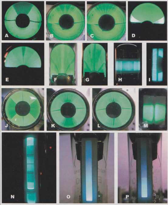 PHOTO 2: Displaying dB steps on different phosphor targets. a: 6U5/6E5 input
grounded. b: 6U5/6E5 with 6dB steps. c: 6U5/6E5 with 3dB steps. d: EM71 input
grounded. e: EM71 with 10dB steps. f: EM80 with 6dB steps 9: EM81 with 6dB
steps. h: EAM86 with 10dB steps. i: 1M801 with 10dB steps on one input and
a floating input on the other. j: (JM4 input grounded. k: UM4 15dB in 6dB steps.
l: UM4 30dB in 6dB steps. m: 6A17 with grounded inputs is too blurry for step
display. n: EMMBO3 10dB steps, with phosphor burn. o: EM800 with fixed — input.
p: EM800 linear display with 6dB steps.
PHOTO 2: Displaying dB steps on different phosphor targets. a: 6U5/6E5 input
grounded. b: 6U5/6E5 with 6dB steps. c: 6U5/6E5 with 3dB steps. d: EM71 input
grounded. e: EM71 with 10dB steps. f: EM80 with 6dB steps 9: EM81 with 6dB
steps. h: EAM86 with 10dB steps. i: 1M801 with 10dB steps on one input and
a floating input on the other. j: (JM4 input grounded. k: UM4 15dB in 6dB steps.
l: UM4 30dB in 6dB steps. m: 6A17 with grounded inputs is too blurry for step
display. n: EMMBO3 10dB steps, with phosphor burn. o: EM800 with fixed — input.
p: EM800 linear display with 6dB steps.
Once the tube is calibrated for the starting and ending points of the pat tern, you can con figure the step size. You can calibrate the size of the dB step for any step size inside the 30dB range of the tube fluorescent target. My three switchable step sizes of 3dB, 6dB, and 10dB are selected by a three-position selector switch on the left side of the schematic diagram in Fig. 4, and are calibrated individually with an oscilloscope.
A fixed step dB sequence is an exponential sequence, in which each step is a fixed percent age of the previous step. The circuit in Fig. 4 generates an exponential step sequence to drive the input grid of the tuning eye tube. I used a simple method to obtain this sequence by sampling the decaying voltage of a precharged RC network.

Above: Fig. 4: dB step generator schematic diagram captured and simulated
with Linear Technology’s free SwitcherCAD download.
The 555 timer U1 tells the LF398 sample-and-hold IC to sample the continuous exponential decay of C3 at fixed intervals, every few milliseconds as seen on the pulse train and exponential decay in Figs. 5-7. This method is very convenient, because all the steps decay by the same number of dB with each new sample, and are adjusted as a group, simply by adjusting the sample rate, or frequency of 555 timer U1. The dB step selector switch simply connects different adjustable timing resistors to this 555 timer U1.
The remaining task in step generation is to recharge the capacitor periodically. The 555 timer U2 sends a 30u-sec. pulse to recharge C3 after it has discharged to 3% or less of the initial charge (3% corresponds to a 30% decay). At the end of the step sequence, the capacitor has discharged to approximately 150mV. This charge decay is needed to cover the 30dB range of the EM84 tube. Initially, C3 is charged to 4.4V through D1. The two 555 timers are coupled with R5 to ensure that the step pattern and the discharge cycle remain synchronized.

PHOTO 3: Top view of dB step generator and VU meter. a) Output offset control
to adjust start of deflection. b) output gain control to adjust maximum deflection.
c) VU display mode; stepped bars over blank background or smooth bars over
stepped background. d) power switch and LED power-on indicator.

PHOTO 4: Step generator controls. a) input attenuator. b) calibration switch.
c) decay: 6dB/sec or 6dB/100ms. d) dB step size. e) phono jack audio input.
f) sub-mini jack dB step output.

PHOTO 5: dB step generator and VU meter driving EM84 fixture.

PHOTO 6: Interior of dB step generator and VU meter, with power supply on
the left side of the lid and input attenuator on the right. Output offset knob
on the lower left and the output gain knob on the lower right.
 TABLE 1: DYNAMIC RANGE IN DB AND VOLTAGE RANGE FOR VARIOUS EYE TUBE TYPES.
Eye Tube | Target | Measured range in dB (specified range in V)

Above: Fig. 5: Two pulse trains sample and reset linear RC exponential decay
to produce precise negative voltage steps in —3dB increments for EM84 triode
grid input. Photo: EM84 with 3dB steps shows 30dB range.

Above: Fig. 6: Slowing the step sampling pulse rate with a single adjustment
yields 6dB steps. Photo: EM84 with 6dB steps shows 30dB range.

Above: Fig. 7: Three 10dB steps fill the 30dB deflection range of the EM84.
Each step is only 31.6% of the previous step. Photo: EM84 with 10dB steps shows
30dB range.
The output of the LF398 sample-and-hold IC swings from —4.8V toward 0V. The LT1057 opamp U5 with Q1 and Q2 form a high voltage amplifier to extend the —4.8V step swing up to an adjustable maximum of —40V to drive the triode grid of the EM84.
Because of working with dB, the number of dB between steps won’t change, while adjusting the overall step amplitude to fit the maximum input voltage range of the indicator tube. The negative input voltage needed to maximize deflection of the fluorescent pattern is specified at —22V for the EM84, and —10V for the pin-compatible EM87. In practice, these voltages can vary up to several volts, so adjustment of the input amplitude may be needed to get maximum deflection.
The dB selector switch selects between three pre-adjusted timing resistors of the first 555 timer U1 to sample the decaying exponential voltage on C3 more frequently for small dB steps, or less frequently for large dB steps. Compare Figs. 5-7.
The following describes the calibration method for the dB step size:
For the 3dB step, adjust RU10 trim pot to get steps that are 70.7% of the voltage of the previous step. For the 6dB steps, adjust RU7 with a slower step rate to get each new step at 50% of the previous step, and for 10dB steps, slow down the step rate with RU8 to obtain steps that are only 31.6% of the previous step. This is best done with an oscilloscope, but you can make these adjustments using the EM84 by applying known DC voltages with these dB ratios, and then adjusting the timing resistors for 555 timer U1 until the step size shows the same deflection as the known DC voltages.
DISPLAYING DB STEPS
The dB step generator is useful to check various indicator rube types, and to compare various tubes of the same type from different manufacturers or different levels of wear (Photo 2). Other tube types, such as the classic round eye 6U5/1629, the bathtub target EM8O/EM81/EM85, or the off-center round fan deflection EM71, have a logarithmic deflection characteristic, but the smaller deflection area makes them harder to read. The dark portions of the concave targets tend to glow slightly.
As a result, concave metal targets offer a lower contrast than the phosphor tar gets that are painted on the glass. In this group of round eye tubes, the EM71 is the most suitable with its wide deflection area. The EA1YE86 has a rectangular side view pattern like the EM84, and the deflection is horizontal rather than vertical.

Above: Fig. 8: VU meter with 6dB graduated scale. Photos: Two display modes
on EM84 with the same input: a) graduated bars over a dark background; b) smooth
bars over a graduated background.
-5V to 0V Exponential steps from LF398 Sample-and-Hold at FIXEDSIEPS Audio input at AUDIOIn; Negative drive to tuning eye amp at MOOSTEPS
Display mode DPDT SW:
-graduated bars over blank background,
-or smooth VU bars over graduated background.
Step Limiter/Modulator; Limit Positive or Negative
Full Wave Peak detector; 24dB gain for -5V max Output peak at C1

Above: Fig. 9: Schematic diagram for dB step modulator. AUDIO_in is peak
detected and limits the dB step sequence input at FIXED STEPS, to indicate
VU level at MODSTEPS.
The EMSO is a variant of the EM84 that shows two identical channels on the same phosphor target. It has two rectangular patterns adjacent to each other, but they are narrower, slightly distorted, and are harder to read.
The EM800 is the only eye tube I have found with a linear deflection scale, which makes it unsuitable for use with the dB step generator, as notice in Photo 2-p. It’s pin-compatible with the EM84, and the deflection pattern is only one single bar that covers a target area similar to the EMS4. The EM800 requires a 200k plate load on the triode.
The EMM803 has two independent and dissimilar target deflection areas. The longer deflection area is logarithmic and very similar to the target of the EMS4. The shorter deflection area is linear and extends no more than 1/4” just below the main target. You could use this small target area as a multiplex FM stereo indicator.
The 6AL7 tube requires about -10V to +20V applied to its deflection inputs, and it does not include a triode pre amplifier. It also has a blurry beam and short deflection. The deflection response is fairly linear, which makes it unsuitable for use with the log step generator.
ADDING THE VU METER FUNCTION
After working with the dB step generator for a while, I decided to combine the precise steps of the step generator with a live VU signal to produce a graduated VU display on the target of the EMS4. To do this, I added the graduated scale provided by the dB step generator to the VU signal in one of two selectable display modes as shown in Fig. 8. One display mode adds graduated dB steps to the otherwise smooth green rectangles.
The other display mode adds a back ground pattern of fixed steps, with the original smooth bars deflecting over this pattern to indicate signal level. The equal dB steps make it easy to accurately measure the strength of the signal in dB or volts.
The first mode, with stepped bars over a dark background, is generated when the peak-detected VU signal on C1 ( Fig. 10) combines with precision dB steps in U2 and U3 to limit the maximum dB step excursion on the phosphor target. Alternatively, flipping the display mode switch and the VU signal on C1 limits the minimum dB step excursion, resulting in a display of smooth VU bars over a graduated dB step back ground. You can increase the contrast between the smooth bars and the graduated background steps by dimming the background steps slightly (Photo 7). Just increase the value of C2 to 0.01pF to length en the period of the second 555 timer U2 so that the background dB steps spend less time on the target.

Photo 7: EM84 VU display. Increase U2 period to darken the background graduated
steps.


PHOTO 8: Nine examples of EM84 tubes. All tubes show 6dB steps, except for
the Telefunken, El Austria, and Sylvania, which show 10dB steps.
1) EM84 Telefunken
2) 6E3P/EM84 Russia
3) EM84 Mullard
4) EM84-El Austria
5) EM84 Zenith
6) 6E2/EM84 China
7) EM84-RWN Newhaus
8) EM84 Webcor
9) EM84-Sylvania with phosphor burn.
The VU circuit in Fig. 9 generates the VU signal with a peak detector and a calibrated attenuator to obtain full-scale ranges of —10dBV = 316mV peak, 0dBV = 1V peak, +10dBV = 3.16V peak, +20dBV = 10V peak, +30dBV = 31.6V peak, and +40dBV = 100V peak. If you want to use this circuit to monitor maximum power at speaker terminals, you can monitor the power of amplifiers ranging from 12mW peak into 8-ohm with the —10dBV range, as may be the case with a headphone signal, to 1250W peak into 8-ohm with the +40dBV scale. You can also set the decay rate of the VU detector with R4 to 6dB/sec for careful monitoring of maximum swings, or 6dB/150ms to gauge the dynamic behavior of the sound material.
USING THE METER
I found the 6dB step setting most useful to monitor dynamic content in music. The higher resolution of the 3dB step is best suited to check frequency response in an amplifier or speaker system. The 10dB step setting has been handy to check the total dynamic range of EM84 tubes.
One possible setting that can be useful in recording or precise monitoring of maximum signal levels is to adjust step size to obtain just one or two steps for comparison with the incoming VU signal. In the case of a recording level meter, you accomplish this by adjusting the indicator gain to obtain maximum deflection for a +3dB maximum record level. Then, you could ad just the next step to 70.7% of this level for 0dB.
Finally, lower the value of R4 to shorten the period of the second 555 timer U2 to shorten the step sequence to just these two steps. This way, notice very precisely when the 0dB level is exceeded, without any parallax error caused by external bezel markings. In this application, the preferred mode is the smooth VU bars over a graduated background.
Another advantage of combining dB step levels with the signal voltage is that the VU voltage will always be accurately measured with respect to the dB step graduation, even with a change of tubes, or when supply variations affect the deflection factor of the tube. When you change tubes, or as the tube ages, you simply readjust the high voltage amplifier gain to make the green bars meet precisely in the center and readjust the offset control to minimize deflection with zero input and good dB step conformity at the ends of the deflection target. These adjustments won’t affect the relationship between the VU signal and the graduated dB steps, so that measurement accuracy is preserved.
The nature of dB measurements is such that two stepped dB VU meters could be driven by the same audio signal with their two input attenuators set 30dB apart, such that the combined dB measurement range of the two tubes would be doubled from 30dB to 60dB. For example, if one VU meter is set to 0dBV, it will indicate sound peaks from —30dBV up to 0dBV, then another unit could measure the same audio signal with its input attenuator set to +30dBV, so that it can monitor signals from 0dBV to +30dB V.
The VU meter circuit in Fig. 9 includes D5 to limit the output drive when the input is overdriven, but the —10dBV range should not see input signals greater than 5V to avoid damage to the input stage. This expanded dynamic range of 60dB using two eye tubes is particularly useful to monitor classical music, in which the quiet passages are often more than 30dB quieter than the loudest musical peaks.
NOT ALL EM84 TUBES ARE CREATED EQUAL
There is a great variation in brightness and phosphor smoothness. All tubes are driven with 6dB steps, except Telefunken, El-Austria, and Sylvania, which are driven with 10dB steps. You can eliminate the gaps at the center of some of these tubes with a slight increase in input voltage amplitude. You could even out the start of the pattern at the ends of the phosphor target on the El Austria tube with the offset adjust knob. All tubes were able to display the full 30dB range with very good accuracy.
The quality and smoothness of the phosphor target makes some tubes better than others. The brightest ones were RCA, Telefunken, and Russian tubes, which had a somewhat rough target, but were still quite usable. Some house brand tubes such as the RWN-NEWHAUS and WEB COR, were barely usable, with a dim and rough phosphor target.