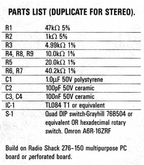
|
|
This simple audio booster amplifier raises the amplitude of a signal up to 15x, and, in a stereo configuration, allows individual adjustment when R and L channels are not equal in level.
Consider this scenario: A user had a signal source connected to the AUX input on an integrated amplifier that had a consistently lower level than the other sources. This made it necessary for the user to advance the loudness control higher to compensate and then experienced “blasting” when setting the input selector to another source. It wasn’t feasible to attenuate the louder sources, so a simple preamplifier was deemed necessary.
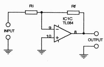
FIGURE 1: Inverting opamp amplifier. Gain factor =Rf/Ri
A physically small preamplifier that would fit the back of the equipment rack was needed. It required that the gain be adjustable from 1 to 15 (22dB). You may wish to plug a different signal source in and adjust the gain accordingly. When the user reconnected the original source, he wanted a way to repeatedly restore the original gain setting.
It is easy enough to design a simple amplifier given the present state of technology But what is the best way to adjust the gain? Memories of pots with pointer knobs and scales and impreciseness come to mind. A 10- or 15-turn trimmer pot would give resolution but no repeatability.
SOLUTION
In dealing with op-amp theory, the inverting configuration in Fig. 1, the expression for the stage gain, directly, relates to Rf/Ri, which is the value of the feedback resistor divided by the value of the input resistor. This is true because the inverting input is held at OV by the action of the op amp and feedback resistor.
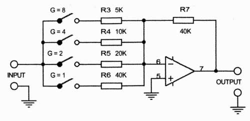
FIGURE 2: Four different switched gain resistors weighted 8-4-2-1.

FIGURE 3: Final amp schematic.
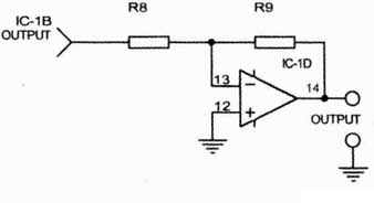
FIGURE 4: Adding former non inverting output.
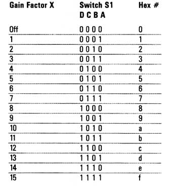
TABLE 1: GAIN SETUP.
In other words, you can change the gain either by holding the input resistor constant and changing the value of the feedback resistor or holding the feed back resistor constant and changing the value of the input resistor.
In Fig. 2, it follows that four different gain selections are possible using four switches and four different input resistors with a single feedback resistor. With the inverting input at 0V, the gain set ting resistors R3 to R6 can work without interaction.
If you select more than one feedback resistor, the overall gain is equal to the contribution of each resistor; i.e., for all switches closed:
Gain = R7/R3 + R7/R4 + R7/R5 + R7/R6
If R6 is 40k (the same value as the feedback resistor), gain = 1, R5 = 20k, gain = 2; R4 = 10k, gain = 4; R3 = 5k, gain = 8.
With this scaling, it is possible to select gain factors from 1 to 15 by set ting various switches to the On position (Table 1). Gain selection can be made a step easier by substituting a hexadecimal-coded rotary DIP switch (Omron A6R-162RF). Codes 10 to 15 are labeled abcdef. This switch will select the proper input resistors for each gain setting.
The final schematic is presented in Fig. 3. The first stage IC-la is a buffer used to isolate the loads presented by R3 through R6 from the input. R2 and C2 form a simple RFI filter to prevent a local A1VI radio station from getting through. C1 removes any DC bias on the input signal. You may add IC-1c after IC-1b for a non-inverting signal output.
Regulated ±12 to ±15V power supplies are required, 10mA maximum; in this situation, the power was tapped off another piece of equipment.
COMPONENT SELECTION
I chose a TL084 quad op amp based on the need for a medium quality amplifier for use with a mid-level signal (0.1 to 1V RMS). You can use low noise or low offset op amps, depending upon your requirements.
The gain setting resistors are 1%, al though you can use 0.5% or 0.1% units to give more precise gain steps. The amplifier is inverting; you may prefer to add A1-C (Fig. 4) to re-invert the signal.
CONSTRUCTION
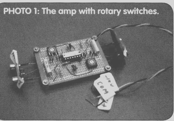
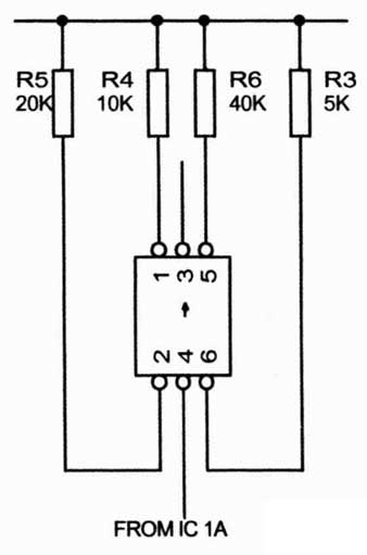
I used standard construction techniques, building a two-channel inverting output unit using two sections each of a TL084 DIP. You may construct version 1 using DIP switches or version 2 using rotary switches (Photo 1). Version 2 requires a different layout of the gain select resistors (Fig. 5) to match the pin layout of the rotary switch.
I built my prototype using a Radio Shack 270-150 multipurpose board, mounting resistors R3-R7 vertically to save space and to minimize the area that IC—1B input includes. You can install the completed circuit board into a small metal enclosure to minimize interference pickup. You can make 1/8” holes to facilitate adjustment of the switches.
USAGE
With the amplifier installed and power applied, start with gain of one and in crease to the desired level on each channel. The frequency response is 10Hz to greater than 20kHz. Distortion measurements were not available.
