With the tremendous interest in High Fidelity, it is obvious that there is a need for a comprehensive handbook with practical plans relating to loudspeaker enclosure construction.
Suitable enclosure design for High Fidelity reproduction has always been an art combined with a certain amount of science and loudspeaker manufacturers usually make available one or two suggested enclosure designs.
However, there has not been any guide available offering such a wide choice as the present volume.
The author would especially like to thank the following U.S.A. companies for making available their suggested designs enabling him to present a range of models from the simplest and smallest to complicated multi- speaker enclosures, suitable for large halls.
One reason for selecting American Designs is because the major loudspeaker factories and acoustical laboratories in the U.S.A. spend a very much larger proportion of their budget in research in this field than is the case in the UK:
ALTEC-LANSING CORP
ELECTRO-VOICE INCORP.
GENERAL ELECTRIC CO.
JENSON MANUFACTURING CO.
KLIPSCH AND ASSOCIATES
JAMES B. LANSING SOUND INC.
RACON ELECTRIC CO INC.
STROMBERG-CARLSON CO.
UNIVERSITY LOUDSPEAKER INC.
UNITED SPEAKER SYSTEMS
CLASSES OF ENCLOSURE
The loudspeaker unit itself is one of the most important links in any High Fidelity chain, but without a suitable enclosure there is no point in installing a high grade unit because without this vital ancillary the loudspeaker is incapable of proper reproduction.
There are many classes of enclosure, of these the most important are the horn, and the direct radiator. Naturally, there are many variations of both of these and plans of an extensive range of both types has been included.
With the horn system, the speaker diaphragm is linked to the air via an impedance structure, i.e. the horn itself. Whereas with direct radiators the speaker diaphragm itself is directly coupled to the air without an intermediate step. Horn enclosures are capable of superb reproduction, but to get a full frequency range, a very large structure is necessary.
This makes them much more expensive than the direct radiator, which can itself, prove to be a very effective design. They reproduce at nearly as high an efficiency and with practically as wide a frequency range as the horn enclosure with the advantage of much lower cost and more important still, much more compact and presentable form.
Correctly designed horn radiators produce no transient generation over a very wide frequency range, resulting in much higher acoustical efficiency than is possible with a direct radiator . In other words, a comparatively low power is required to feed a horn radiator compared to a direct radiator working at the same acoustical level. However, by careful design direct radiator enclosures can be made free of transient generation. An Important feature of the horn radiator is the low distortion factor due to the low power required to load It effectively. Amplifier distortion is likely to be less at a low power level. However, to offset these advantages, the horn enclosure demands much more critical construction than the direct radiator and If required to cover the lowest audible frequencies their physical size tends to become unrealistic. The horn reproducer is used mainly in theatres and large auditorium Installations, where its large size is of no consequence.
Direct radiator enclosures are available in various form such as the infinite baffle, folded baffle, flat baffle, base reflex or labyrinth. Horn enclosures are also found in various forms such as the straight horn, single and double folded horn. Klipsch horn, multicellular horn, etc.
It is possible to utilize combinations of both types of enclosure, such as a direct radiating high-frequency and mid-frequency speaker combined with a rear folded horn radiator operating from the back of the speaker to make the most of the low frequencies.
This guide covers both of these principle types, together with as many variations as possible. No special recommendation can be given for using any special design in preference to another.
Reproduction of sound is very similar to the enjoyment of food, that which suits one listener's ear may not please another persons hearing. However, each of the designs included in this guide have been tried cither by the author and his friends, or by various research institutes and loudspeaker manufacturers, in every case results have given satisfaction to the majority.
It is pointed out at this juncture that most of the designs described are patented and It must therefore be clearly understood that because a design is shown in this guide it does not Imply a license to manufacture for re-sale. Single hand made copies of the suggested enclosures should not, in the opinion of the author, contravene any patent granted to the original designer.
Much of enclosure design is based on complicated mathematical formulae. Because the average constructor has no desire to be taught or reminded of advanced mathematics, the technical reasoning why various dimensions are chosen has been omitted as this is better explained in the learned works available in the field of acoustical engineering.
Bass-reflex enclosures are amongst the most popular types used for High Fidelity reproduction. The critical factors of this design are the port or air gap calculation and the overall enclosure dimensions. These measurements are controlled by a number of factors, the most important are the resonant frequency of the loudspeaker and the physical area of Its cone. These standard factors result from the original work of Helmholtz, etc. and to save readers extensive calculation, a number of tables have been included showing; the port size and length of tunnel dimensions, for a range of loudspeaker sizes with various resonant frequencies. Ideally the proportions of a bass-reflex should be in the ratio of 2 : 3 : 4 with respect to depth, width and height, two extensive tables covering this data are included. It is strongly urged that after constructing any bass reflex enclosure It should be carefully tuned to the speaker or speakers fitted. Tuning means making the port larger or smaller to cope with individual loudspeaker variations. This can be easily effected by means of temporary sliding doors on the ports to permit experimental variation of their physical size. See section on tuning.
TABLES
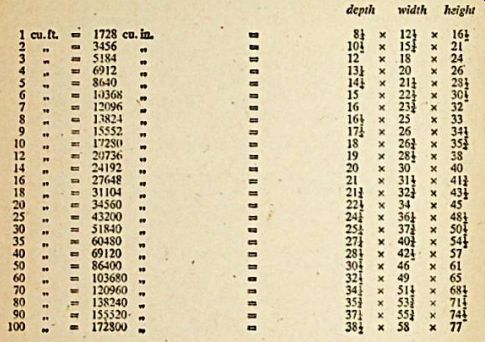
Table A, gives the required dimensions in the ratio of 2 : 3 : 4 that will be needed to construct an enclosure with a volume of any desired number of cubic feet.
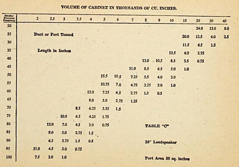
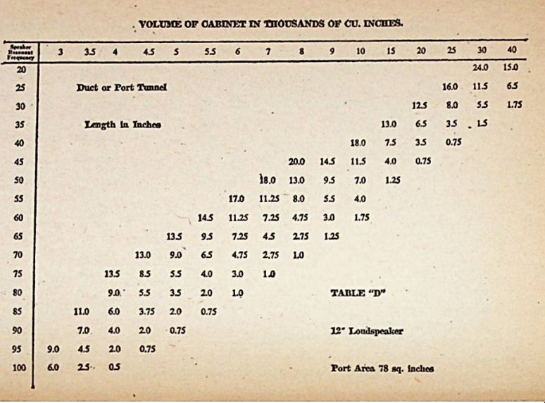
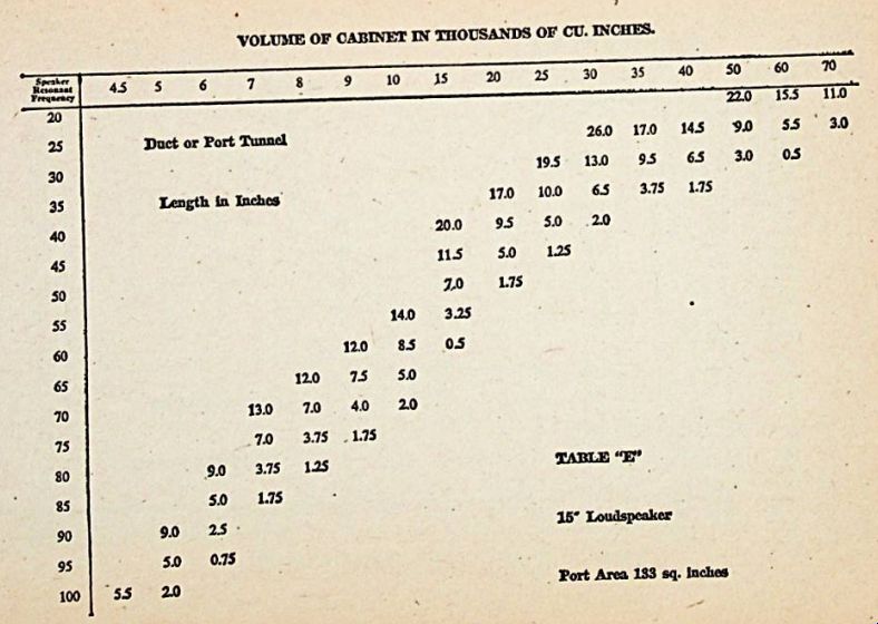
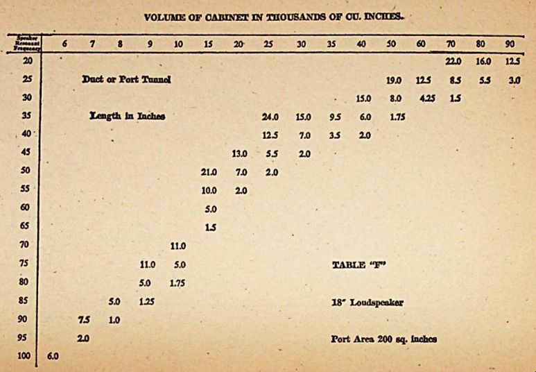
Table B, is similar to Table A except that the required volume is shown in cubic Inches Table C, D, E and F arc to enable the reader to assess the cubic capacity required for an enclosure depending on the resonant frequency of the speaker to be used. At the same time, the actual port area and port depth or tunnel length is shown. These four tables cover 10, 12, 15 and 18" loudspeakers.
Further Information on using these tables is given in the section headed USING TABLES A - F.
Many of the designs in this guide use more than one speaker, this is because even the most perfect loudspeaker can produce only a limited range of frequencies. High Fidelity reproduction over the useful audible frequency range, i.e. from 30 hz. to 17,500 hz., require a combination of two or more loudspeakers. A bass unit covers the low frequency band, i.e. 30 hz to 5,000 hz and a high-frequency tweeter to reproduce 5,000 hz upwards. Sometimes the audible range is split up between three speakers . In this case, a medium size loudspeaker is used in addition to give brilliance to the middle register say from 1,000 to 5,000 hz.
When selecting a loudspeaker, particular attention should be given to the size and weight of the magnet used. A large heavy magnet is necessary for high acoustical efficiency. Readers should not be misled by advertisement claims of very high gauss, unless combined with very heavy magnet weight i.e . in the case of a 12" speaker a recommended minimum weight of at least 48 ozs of magnet is suggested.
Checking this point is especially Important as many manufacturers simply give the magnetic flux density, but do not state the actual weight of magnet used in the speaker. This is often as low as 4 to 5 ozs. 8" speakers require a minimum magnet weight of 16 ozs., tweeters of 2" to 4" diameters, 4 ozs.
Timber choice is left to the constructor, however, a thickness less than that recommended should not be considered. Experience has proved that high grade bonded ply is one of the best types of material available because it does not suffer from distortion or warping and is usually well seasoned before delivery to wood merchants. Much experimenting can be carried out to improve the response and to eliminate transients on bass-reflex or direct radiation enclosures with damping materials, such as fiberglass, thick felt, blanketing etc.
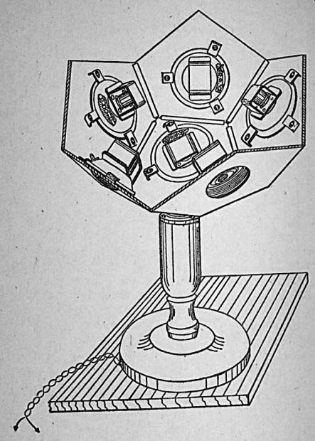
Fig. 1. For the first time a practical spherical tweeter reproducer is
shown. A working model of this assembly was demonstrated at the Hanover
Fair in 1956 and aroused considerable Interest. Since then, descriptions
have appeared in German and French radio publications. Twelve tweeters
arc used and sound dispersion is completely omni-directional.
The finished appearance is rather similar to a sphere of 14" dia. Mounting can be effected in a number of ways, either on a lamp standard, so that it is placed above the main middle and bass enclosure or alternatively, particularly effective results are achieved If the unit is suspended from the ceiling, as though It were a pendant lamp.
------
TABLE "A" DIMENSIONS IN INCHES TO GIVE REQUIRED ENCLOSURE VOLUME IN CUBIC FEET.
TABLE "B" DIMENSIONS IN INCHES TO CUT
-----
-----12
-----13
-----14
Wood used for the original model was 1/2" ply and all 12 pentagons fixed together internally in the form of a sphere by using Inexpensive miniature hinges, thus making a most effective unit with a minimum of labor and at low cost. See Page 40 to 42.
It is very Important that the Impedance combination be calculated to suit the impedance offered at the output of the amplifier. A series-parallel arrangement is necessary.
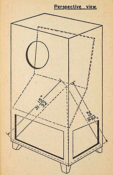
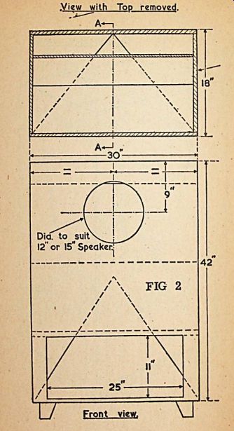
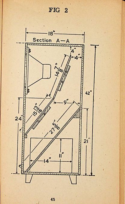
Fig. 2. Particularly recommended for superior performance where 12" or
15" bass speakers are used and is a combination of bass-reflex with
all the assets of a horn reproducer combined. Constructional details are
clearly shown, of special interest is the pyramid reflector in the bottom
portion of the unit, which provides perfect diffusion. See Page 43 to
45
Fig. 3 Recommended where overall size is an Important factor as with the modern living room. It is a true example of the tuned port bass reflex cabinet, and should be built of seasoned timber, minimum thickness 7/8". Alternatively, good quality ply of similar thickness can be used. The base legs can be made to suit Individual tastes.
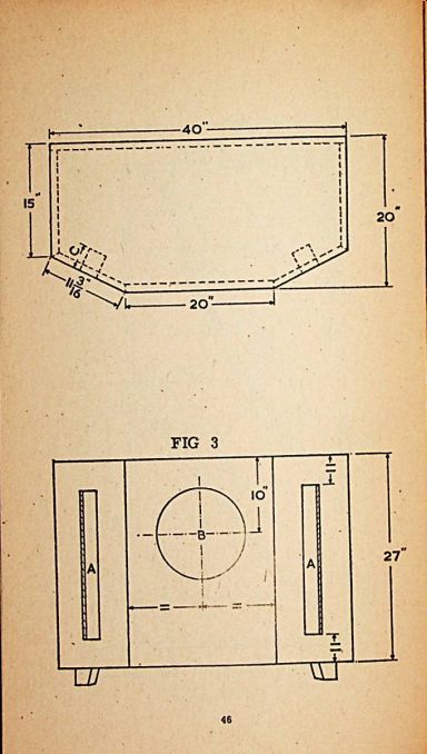
Height from the floor should be approximately 3". Originally this enclosure was constructed for use with a 12" speaker, but with the changes in the port size it is also suitable for speakers of 10" or 15" diameter. See Page 46.
Dimension A = 13" x 2" for 10" loudspeakers
Dimension A * 13" x 3" for 12" loudspeakers
Dimension A = 13" x 5j" for 15" loudspeakers
Dimension B = Cut to suit speaker size
Dimension C = is obtained by reference to depth of port tables on Page - according to speaker size.
This dimension is also dependent on the fundamental resonance of the speaker used and the tables cover this requirement.
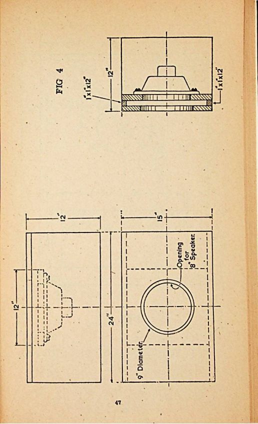
Fig. 4. The "Library Enclosure". This is an efficient tuned
port bass-reflex enclosure of high quality. It is designed for use
with a good quality 8" loudspeaker, resonance about 75 cycles. From
the dimensions of this enclosure It will be seen that It has been specially
designed to fit into book selves without being obtrusive. See Page
47.
It is very simple to construct, but essential that all timber used should be a minimum thickness of relevant dimensions are clearly shown on the diagram. Particular care in fitting should be taken with the back, top, sides and front which should be made as airtight as possible.
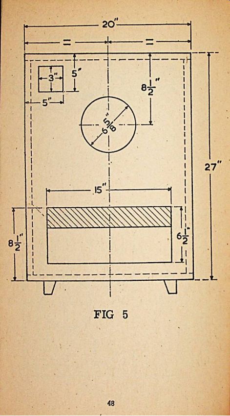
Fig. 5. This miniature horn loaded reflex enclosure is eminently suitable
for small installations where space is limited. Genuine High Fidelity
is satisfactorily achieved using a loudspeaker of 8" diameter. Due
to the unique horn loading and the tuned port, reproduction from this
enclosure will delight the most critical listener. Because of the small
physical size, It is stressed that the minimum thickness 6hould be for
all timber used for this model. See Page 48 to 49
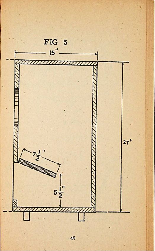
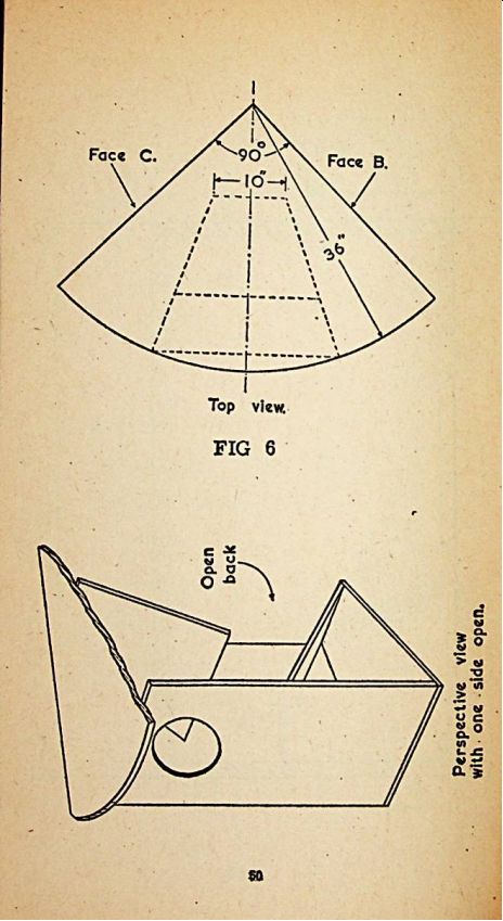
Fig. 6. The 12" Mini-horn.
A horn radiating unit which eliminates any tendency to transient generation,
it has very extended frequency range and high acoustical efficiency. The
major asset is that the minimum quantity of timber is used in construction
because two walls of the room arc used to form the major sides of the
horn itself.
Particular care roust be taken when building this enclosure to see that the top is exactly 90° or ¼” circle in order to (It into the room walls. It is suggested, that to obtain optimum results, (aces "B" and "C" should have a small strip of felt attached to form an air seal. Because o( the high acoustical efficiency a 10" speaker is quite suitable, though a 12" unit can be used by increasing the size of the aperture. Other dimensions remain as shown in the diagram. Timber used for this enclosure to be of minimum thickness of 1" because the frequency range is extended down to 30 cycles. See Page 50 to 51
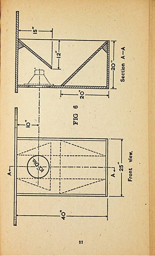
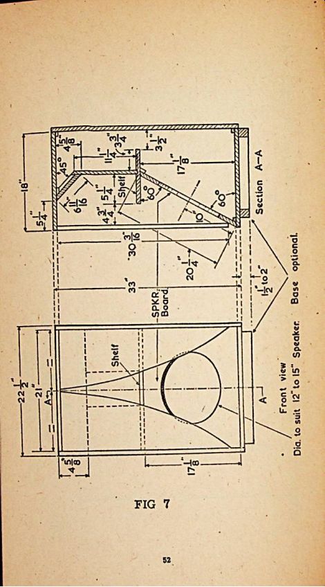
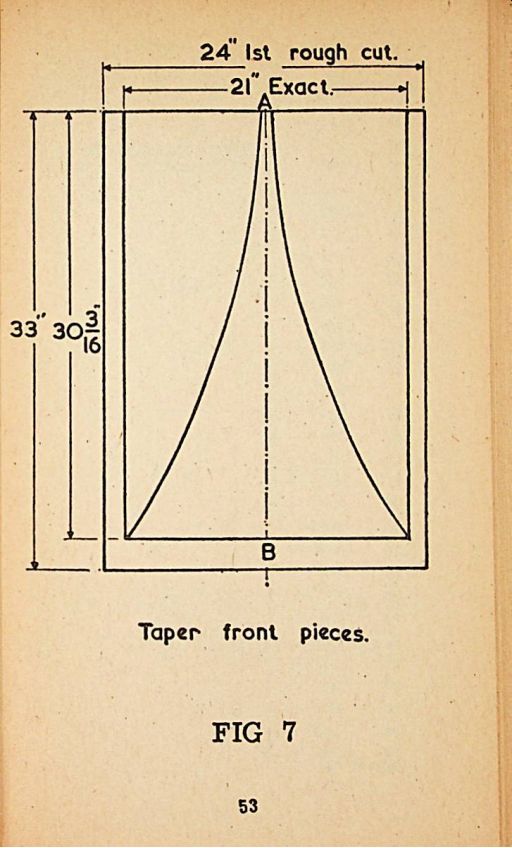
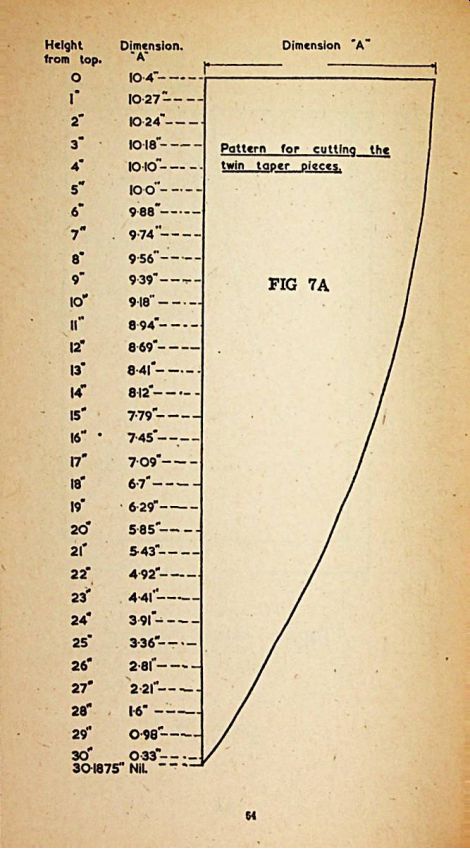
Fig. 7. Here is one of the most popular
types of enclosure. Originally designed by John E. Karlson (recognized
to be a leading authority in this Held). Results from the Karlson enclosure
undoubtedly exceed the expectations of the most severe critic and fully
warrant the considerable amount of time taken up in construction. See
Page 52 to 54.
Timber must have a minimum thickness of 1", the only critical items are the twin taper front pieces, which are mathematically calculated and these dimensions must be maintained within + 1 /32 inch. To aid construction the curved shape of these pieces is carefully dimensioned, in Fig. 7a. It is suggested that a full size paper pattern be made from the diagram and two pieces of wood cut at the same time thus ensuring that both pieces arc identical.
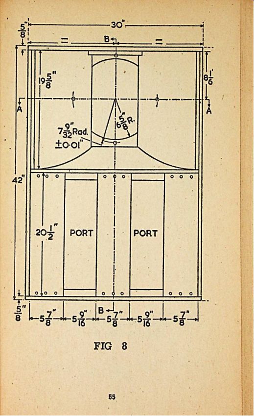
Fig. 8. This enclosure was designed by the Altec Lansing Corporation
of America and Included many of the best techniques for a semi-folded
horn, using tuned ports and a Hatred neck. It is a large enclosure Intended
(or use in small halls, auditoriums or very large rooms. When used with
a 15" speaker as recommended, High Fidelity reproduction down to
20 cycles may be achieved. All paneling to be of a minimum of 5/8" thickness,
unless otherwise shown, and all joints must be glued and screwed unless
required to be removable.
7.5" x 16" fiber glass, 1" thick, should be placed on the inside of each side panel, on the Inside of the top of the cabinet and at the rear of the speaker. This is where the 16" dimension is shown in section B-B. A dynamic high-frequency tweeter should be used with this enclosure in a separate mounting so that full range response may be effected.
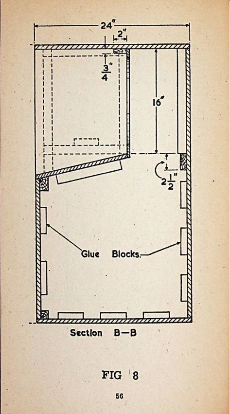
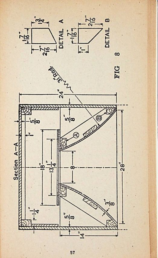
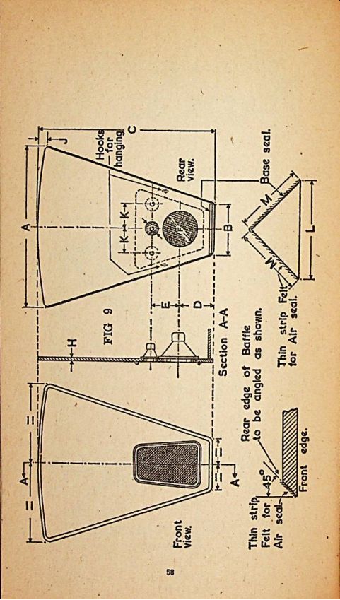
Fig. 9. The Infinite Wall Baffle. A unique design having the great advantage
of taking up no valuable space in the modern small living room, because
in use it is suspended from the picture rail in a right-angled corner
of the walls.
Where a dl-axial speaker is used, omit opening G, as the tweeters are mounted on a bridge across the front of the main speaker. With ordinary 12" bass speakers it is essential that two tweeters be fitted as per dimension K. See Page 58.
The following table of dimensions is Included to enable constructors to build the Infinite Wall Baffle using either 8", 12" or 15" speakers: See Page 55 to 57.

--------- Speaker Dimensions
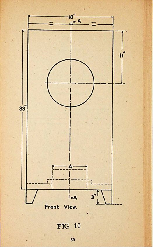

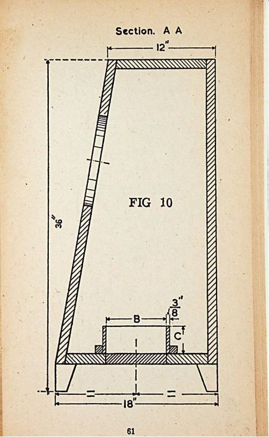
Fig. 10. A modem bass-reflex enclosure with bottom fitted tuned port.
This enclosure takes full advantage of the natural baffling qualities of the room flooring because the tuned port is placed in the base of the enclosure.
Because of this, better equalization and response distribution is obtained.
Timber of not less than 1" thickness must be used, so that all unpleasant resonances are eliminated. The Inner back wall, Inner top and inner two side walls are lined with thick felt or fiber glass for damping purposes.
Critical Dimensions
See Page 59 to 61
For 10" speakers "A" = 7"
For 12" speakers
"A" = 8 7/8"
"B" = 8 7/8"
"B" = 7
Dimension "C" varies according to the resonant frequency of the speaker.
10" Loudspeakers
70 - 90 hz. Dimension "C" = 1/4 " 65 hz.
60 hz.
55 hz.
Dimension "C" = 3"
Dimension "C" = 4i"
= 7j"
Dimension "C"
12" Loudspeakers
Dimension "C" = i"
Dimension "C" = 2}"
Dimension "C" = 6"
Dimension "C" = 10i"
80 hz.
75 hz.
70 hz.
65 hz.
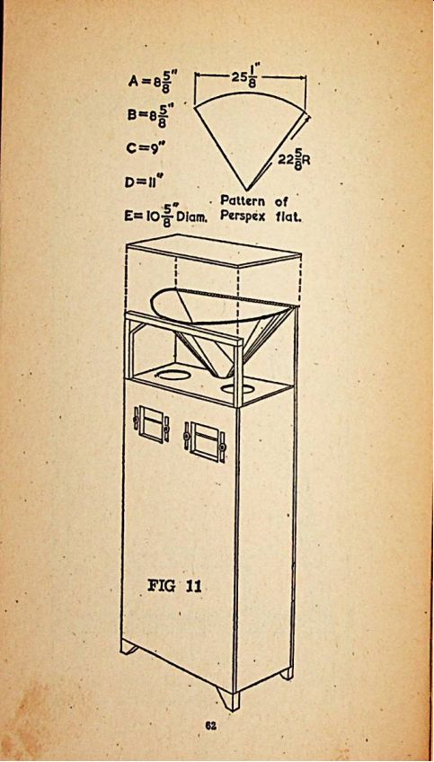
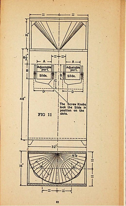
Fig. 11. A large enclosure with dual column reflector system based on
certain patents. Unique in as much as that it produces complete 180° balanced
reproduction, it is eminently suitable for large rooms or halls.
It is for use with a 12" speaker and variable tuned ports are arranged on the front of the enclosure, these are separately tuned acoustically to suit the pair of loudspeakers used. It is vital that the two units are correctly phased. The top semi-circle reflector is made of two pieces of 1/8" thick perspex bent into a cone shape and held by strips of wood. The resulting cavity should be filled with plaster of paris and allowed to set.
This is to eliminate any sympathetic vibrations in the most important part of the enclosure, the reflecting unit. Smaller loudspeaker units may be used, if required, reduce these dimensions in the ratio of 5 : 6 for a 10" unit and 2 : 3 for an 8" loudspeaker. See Pago 62 to 63
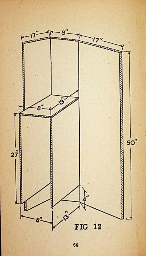
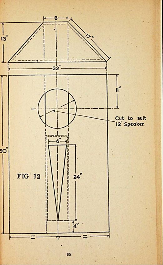
Fig. 12. Corner fitting long channel horn enclosure utilizing any
two walls at right-angles to one another as the main enclosure walls.
The main advantage of this design is the long path formed for the sound
to travel before emerging so that particularly good response is achieved
at bass frequencies. Physically, very little room is taken up because
of the corner fitting. Timber of not less than 1" thickness must
be used and to avoid any resonant effects it is suggested that fiber glass
or thick felt 1" thickness be tried in various positions at the rear
of the enclosure. It is impossible to specify just where to dampen the
enclosure because this factor is dependent on the loudspeaker unit selected.
See Page 64 to 65.
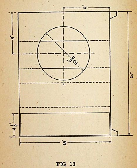
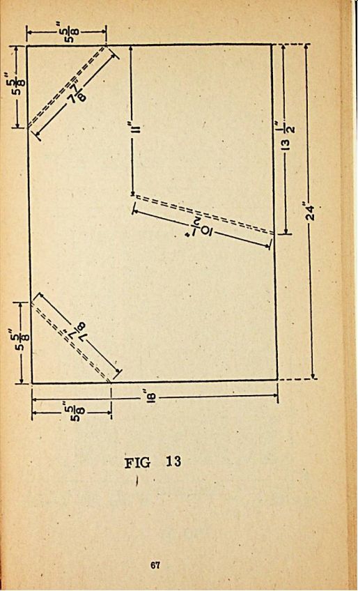
Fig. 13. Long channel enclosure for a 12" loudspeaker. An attractive
model designed with minimum dimensions. Simple to construct and in spite
of its small size, capable of providing good quality reproduction over
a wide range. It compares very favorably with much more elaborate and
expensive enclosures. See Page 66 to 67.
Efficient, acoustically, because a comparatively long path is secured for the rear loading of the speaker. Timber for this enclosure can be 5/8" thick provided the interior is well strutted to obtain extra rigidity. By using 1/4" timber the necessity for strutting can be avoided.
If it is required to use an 8" speaker, reduce all dimensions on the diagram in the ratio of 2 : 3. Damping the interior will improve results.
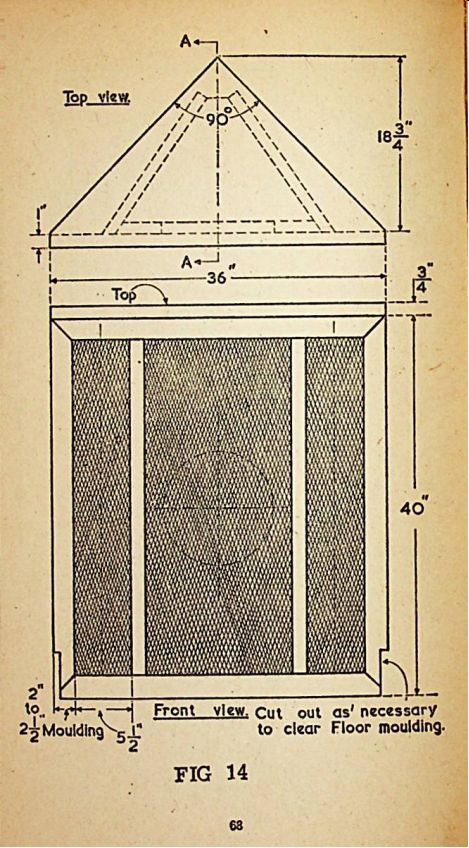
Fig. 14. This is a rear large horn slot loaded corner enclosure intended
for use with 12" or 15" speakers. It will reproduce with clarity
and true fidelity down to the lowest audio frequencies. This design
relies on two right-angled walls of the room to form the balanced porting
and outer walls of the enclosure. Because of the generous size of the
unit, it is recommended that it should only be placed against walls which
are of solid brick or concrete structure. It must not be used against
thin partitioning which would set up unpleasant resonances, see Page 68
to 70
All timber to have a minimum thickness of
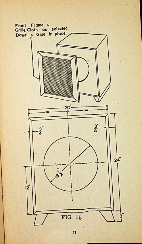
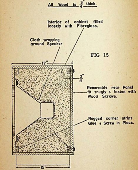
Fig. 15. Probably the
smallest enclosure that will give proper reproduction with 12" and
15" loudspeakers.
Its remarkable results are due to pneumatic suspension but perfect
results are only obtained provided the whole of the interior is loosely
filled with fiber glass wool thus giving the effect of a much larger enclosure
without extra cost. Dimensions are for a 15" unit, if a 12" speaker
is to be used, reduce the dimensions in the ratio of 4 : 5. See Page
71 to 72.
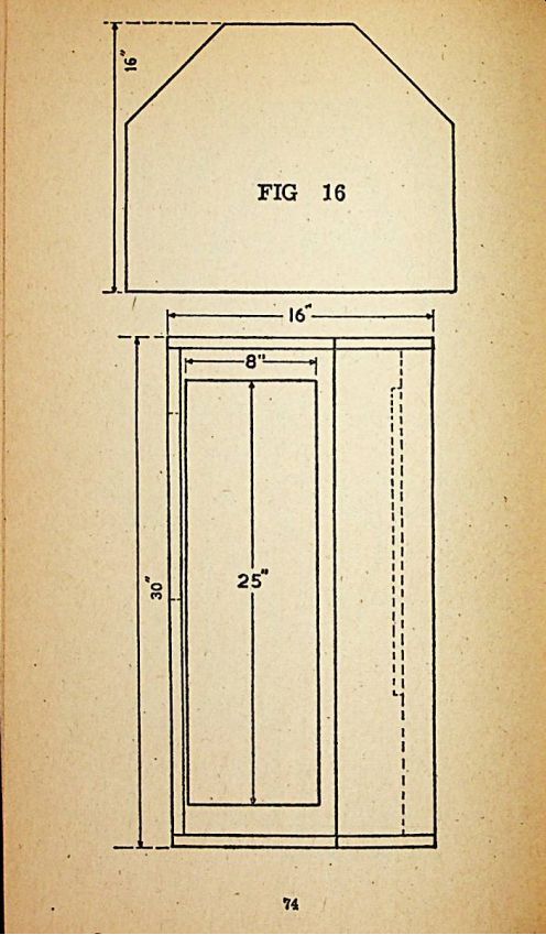
Fig. 16. A novel sealed cabinet design, which has the advantages of the
standard bass-reflex combined with the long path of horn type enclosures.
Sound distribution is effected as follows, direct radiation from the front and back loaded output from the two side ports. Measurements shown on the drawing are Intended for use with a 12" loudspeaker. If required with a 10" unit reduce dimensions in the ratio of 5 : 6 or 2 : 3 for an 8" loudspeaker. One inch timber is used throughout, see Page 73 - 74
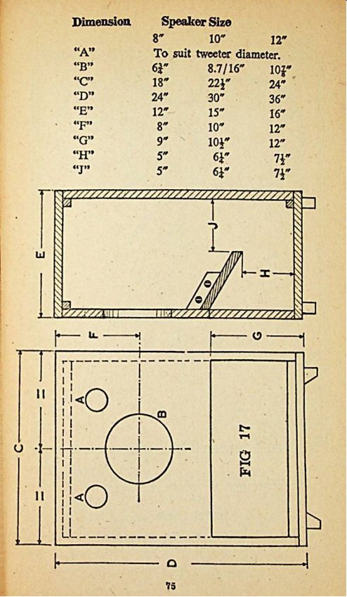
Fig. 17. Rear horn reflector enclosure suitable for the small
home, designed for use with 8", 10" or 12" loudspeakers.
A very simple design that is not at all critical in assembly and will
provide pleasing results with the minimum outlay in time and expense.
Timber used, J" throughout. See Page 75.
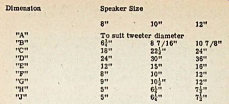
Tweeter apertures "A" are used only when two separate tweeters are fitted. These apertures are not required if a di-axial speaker with bridge mounted tweeters is fitted. The faces of apertures "A" must be centralized in relation to the size of the bass speaker. Detailed is a table of dimensions for use with the three recommended speaker sizes
-----Dimension | Speaker Size
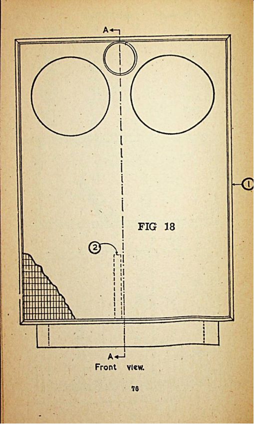
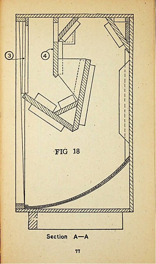
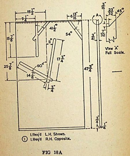
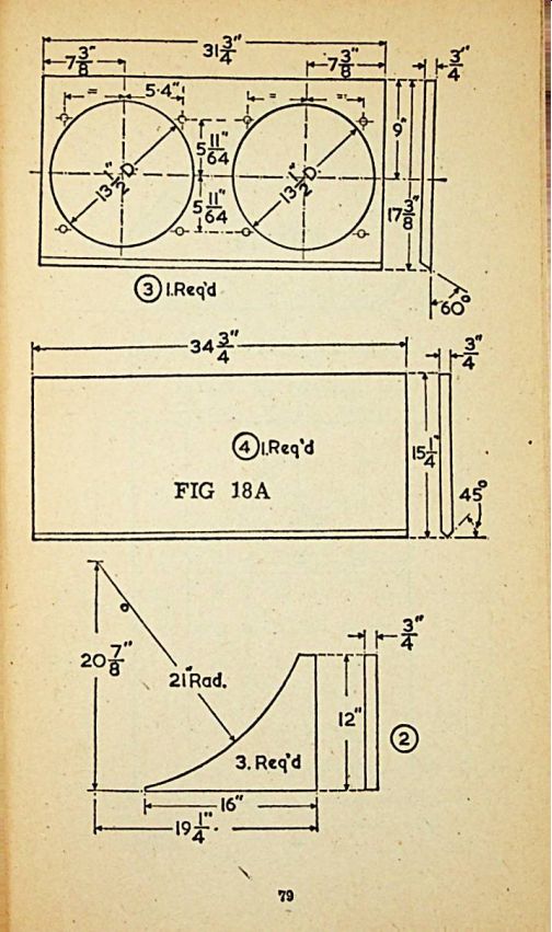
Fig.
18. For outstanding reproduction and where cost is not a vital factor,
this folded horn design will satisfy the most exacting requirements.
Two 15" speakers are used and careful assembly is most Important
as the rear loading has been mathematically and acoustically calculated.
Irrespective of size or price, it would be difficult to improve on the
results obtained from this design. Adequate Interior damping must be provided
by using fiber glass of not less than 1" thickness, firmly secured
to the rear wall of the circular sloping exit chute. Unless the prospective
constructor is an expert wood-worker, the author suggests that this design
be given to a professional cabinet maker to construct, as perfect rigidity
must be secured. See Page 76 to 79
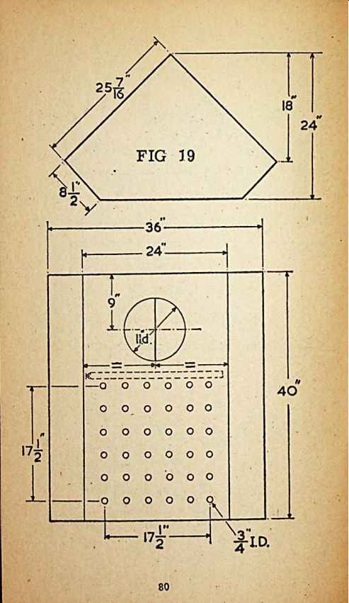
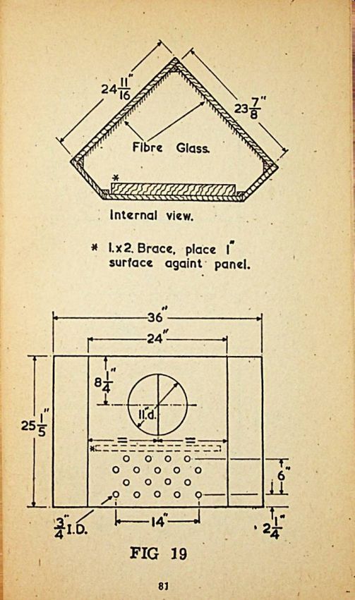
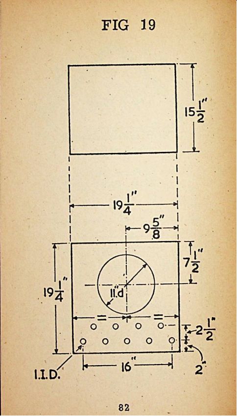
Fig. 19. One of the latest developments in High Fidelity
is the distributed port enclosure. A " Distributed Port" enclosure
is a reflex in which back and front radiation are added at low frequencies.
Low frequency response and the power handling ability are both improved
by using this system. It differs from most reflex enclosures in that the
response and impedance characteristics are controlled by the addition
of a specific amount of acoustic resistance.
There is no cancelling between the front and back radiation at high frequencies due to the fact that the reflex action has an inherent back radiation high frequency cut off characteristic.
Three models are shown, ten six and three cu. ft. capacity, respectively. Plywood of not less than 4" thickness is used for the 3 and 6 cu.ft sizes and 5/8" for the 10 cu. ft. model. Line the back, bottom and one side of the 3 cu.ft. enclosure with 1" thick fiber glass or good quality felt. Line bottom and two rear sides of the 6 and 10 cu.ft. enclosures with 2" thick fiber Glass or equivalent acoustical damping material. Glue and screw all joints and make the front or back removable, if the speaker is to be mounted on the inside surface of the mounting board. The 1" x 2" brace is to prevent reverberation in the front panel which would ruin the low frequency performance. The shape of the enclosure may be altered to suit the user, provided the Internal volume and configuration of the front panel is maintained. This enclosure has been designed to use speakers up to 12" diameter, if a larger unit is used, the power handling capacity will rise, but poorer low frequency response will result. Speakers of smaller diameter will give a better low frequency response but poorer power handling capacity. Loudspeaker units exceeding 12" diameter should not be in the 3 cu.ft. enclosure, neither should units less than 12" diameter be used with the 10 cu.ft. enclosure, see Page 80 to 82.
The original development work on this remarkable design was carried out by the Audio Engineering Division, T.V. Dept., GE of America, America.
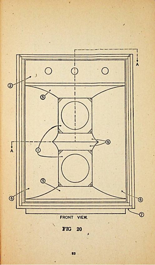
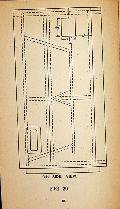
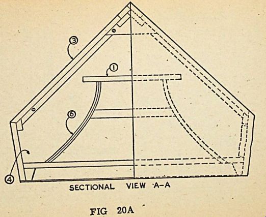
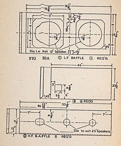
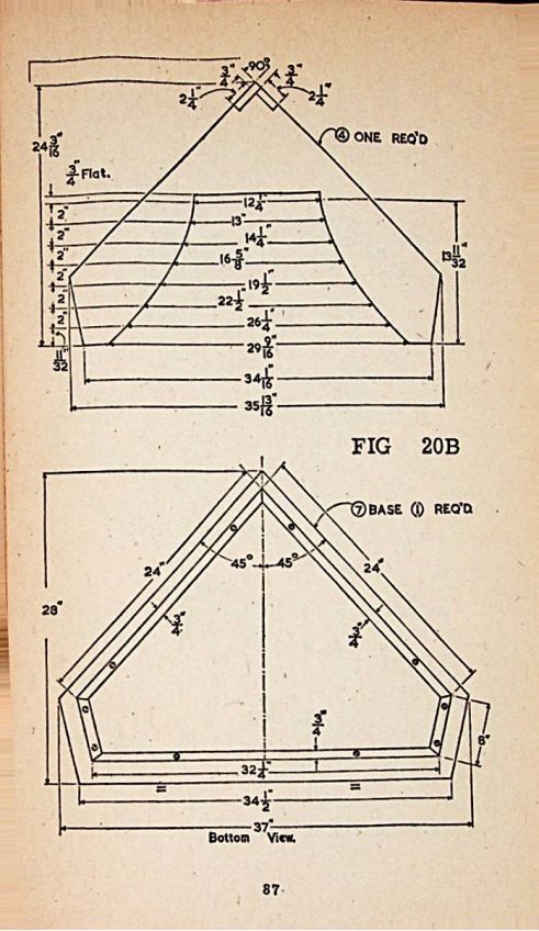
Fig. 20, 20a and 20b. This is a large design recommended for multispeaker
installations for use in large halls, auditoriums and theatres, etc.,
the design uses two 12" speakers for bass reproduction, and three
tweeters to take care of the upper register. Constructors who wish to
build this model, will have no difficulty in following the three drawings
provided, which are self explanatory. See Page 83 to 88.
USING TABLES A TO F
Tables C, D, E and F enable constructor to design ducted bass reflex enclosures. Loudspeakers of 10", 12", 15" and 18" diameters are covered by these tables. To use these tables, first ascertain the resonant frequency of the speaker to be used. This may be obtained from the technical data Issued by the maker. From the table it will be noted that there is a choice between various enclosure volumes and duct lengths, e.g. on table 1 with a 10" speaker with a resonant frequency at 50 hz choice is available from 5,000 to 10,000 cubic inches volume with the duct lengths from 15j" down to 3" respectively. If a small enclosure is required, the duct length will be longer in proportion. Essentially, the duct length must not approach the back wall of. the enclosure nearer than half the diameter of the speaker used.. Because of this, the first choice of cabinet volume and duct length may have to be revised, to ensure that these conditions are met . Interior dimensions of the bass reflex enclosure may be selected from tables A or B, which enable constructors to check if there is sufficient room for the required duct length.
The tables give the required height, width and depth in the ratio of 4:3:2, which is the most suitable acoustically. Table A covers capacities of 1 to 100 cu. ft. Table B from 500 to 40,000 cu inches.
GENERAL CONSTRUCTION HINTS
Perhaps the most Important single factor in loudspeaker enclosure construction is rigidity. Loudspeaker baffles are not sounding boards as used on pianos or violins and Intended to amplify sound, they are Intended to control the sound waves created by the loudspeaker unit.
Any vibrations in the cabinet structure absorb power and re-radiate spurious sound waves at certain frequencies. Rattles or at least response variations due to interference patterns will result and adequate use of bracing cleats of solid timber is suggested. The plans specify 0.25" or 1" plywood for all enclosures except the small ones using 8" speaker units where 1/2" material will usually suffice. Bracing cleats should be fastened securely with glue and screws. The best test for adequate rigidity is to thump the center of all panels with clenched fist; a vibrating panel will quickly reveal its existence by the hollow, drummy sound indicating that further bracing is necessary.
All enclosure Joints should be air-tight. Recommended procedure is liberal use of glue and woodscrews for pulling joints tight. This is particularly important in horn type enclosures. Caulk all Joints after the enclosure is completed with a material such as linoleum cement, which will not become brittle with age.
Avoid any restrictions, cavities or openings which are not specifically called tor in the enclosure plans, because these create resonance effects which destroy realism. Enclosures of peculiar shape may have resonance effects often called organ pipe effects at some frequencies, these are the result of "standing waves". Proper use of absorption material (specified in some plans) will eliminate any ill effects. Absorption material should be located at the ends of the longest dimension which forms the "organ pipe". No absorption material is necessary or desirable in horn enclosures.
Enclosure Interiors may be treated with a sealing medium such as shellac to prevent moisture absorption and thus prevent warping and splitting.
No other finish is necessary on the cabinet. Fasten the loudspeaker unit tightly to the speaker outlet so that no air can leak through from front to back. Most speaker units arc provided with a felt surround to implement this procedure. Flexible mounting supports should not be used for the loudspeaker unit. If feedback is encountered, either mechanical or acoustical, use shock mounts for equipment other than the loudspeaker unit. Shock mounts or the existence of an air leak around the speaker unit will substantially impair the performance characteristics of any good enclosure.
Note that the loudspeaker enclosure is a very definite part of the reproducing system at low frequencies and the particular design is directly related to the loudspeaker unit. The performance of high frequency units is essentially independent of the enclosure except for secondary effects.
EMBELLISHING SPEAKER ENCLOSURES
Without ornamentation the loudspeaker enclosure is nothing more than a plain simple box-like structure that could hardly be considered a piece of furniture. However, with a little patience and skill it is possible to make it attractive and to harmonize with other room furnishings.
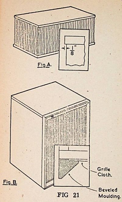
One way is to cover the front and sides with grille cloth, as shown in Figure 21a. This is most practical on small cabinets, especially where the cabinet has been made of plywood since the cloth covering conceals all exposed joints and edges. See Page 89 to 90.
Neatest finish is obtained by extending the top and bottom 1/8" beyond the sides and front during construction. This 1/8" overhanging lip conceals the edge of the cloth top and bottom, thus making an exceptionally neat job.
Should the enclosure have been built with the top and bottom, flush with the sides and front, separate moulding can be fixed to the edges of the top and bottom to create an overhanging lip. Paint, stain or varnish can be used to provide a finish for the top and bottom.
Grille cloth can also be used to cover the entire face of a cabinet even though the speaker opening occupies a relatively small area of this panel.
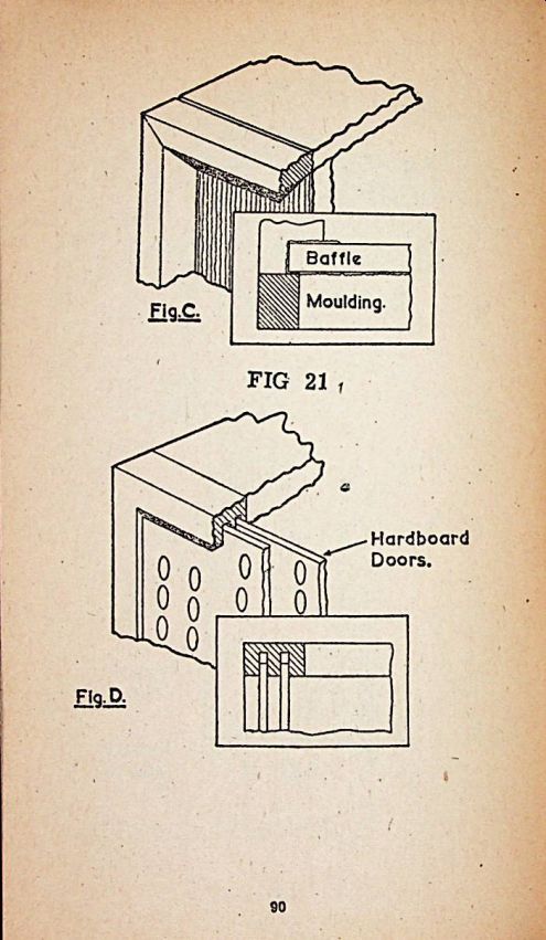
Wooden moldings are available in many forms and can be used to add finish to a plain cabinet. Figure 21b shows the addition of a heavy bevel moulding to the front of a cabinet. Such moulding can be made by cutting diagonally a square section after which a shallow groove is formed on the back before the ends are mitred. It is assembled like a picture frame.
The grille cloth is mounted on the front of the cabinet before the frame is attached, the rabbet being just deep enough to accommodate the grille cloth. For modern effects, bevel and square moldings are perhaps the best. More ornate forms may prove useful with certain cabinet styles.
Generally, choose small moldings for small enclosures and heavier ones for the larger variety.
Moldings must not encroach on the required openings in an enclosure . In some cases the space is not adequate to permit their use. One method o( obtaining additional space to support a suitable moulding is to add a second layer of plywood, in other words, a double top.
A sunken effect similar to the beveled moulding effect may be obtained adding a plain 1/4 " frame to the front edges of the sides, top and bottom as shown in Figure 21c. This permits the grille cloth to be wrapped around the speaker baffle, tacked on the back and then Inserted in place against the projecting front frame.
A similar effect can be achieved by allowing the sides, top and bottom to project forward ahead of the cabinet front by about one inch. Then the grille cloth can be stretched over a light frame work which will just slip Inside the projecting edges against the front panel. This frame can be tacked to the cabinet front with small finishing nails through the openings of the grille cloth.
With some installations, sliding doors of perforated hardboard will prove very helpful. These impart a modern appearance to grouped wall units.
They are particularly useful for amplifier storage units and other types of equipment such as record storage cabinets. Figure 21d shows how sliding doors of this kind are installed. Use care in planning the cabinet arrangement when using them because only halt of the door area can be open at one time. Careful thought will solve this problem for example, the record storage space and a television receiver can be behind a pair of sliding doors since the one will never be used when the other is in operation.
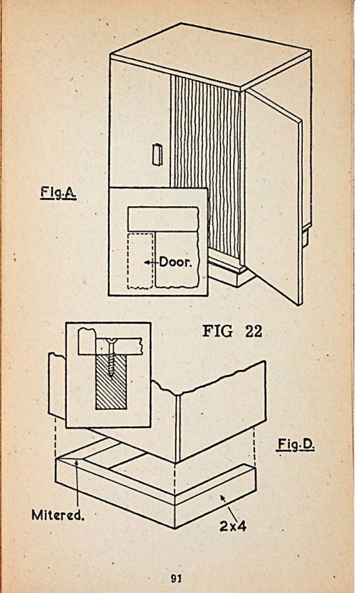
Figure 22a shows how full length hinged doors of veneered plywood can be fitted to individual cabinets. These are more suitable for elaborate expensive cabinets. Both top and bottom of the cabinet project at the front and the doors hinged to the top and bottom with special flat pin hinges. Properly fitted, these doors can swing around against the sides of the cabinet. See Page 91 to 92.
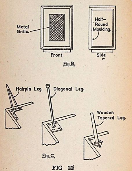
...in many cases picture-frame type overlays of flat and half-round moldings will Improve a plain cabinet. These can be applied to the sides as well as to the front in the manner suggested in Figure 22b. A number of Interesting possibilities of this kind exist.
Perhaps the most important contribution for the home workshop in recent years has been the durable, decorative laminates (often known as counter-top material) available in rich, simulated wood grains. A plain plywood cabinet can be made Into a reasonable piece of furniture by covering It with this material. The new contact cements make It easy for anyone to apply the laminate since clamping is not necessary.
Choice is available of several ready-made legs that will give any low-boy cabinet a smart modern look. Most popular of these perhaps is the hairpin type of wrought iron legs which can be purchased in various lengths at almost any hardware or department store . In addition to the hairpin type, there is the straight rubber-tipped diagonal leg, which like the hairpin leg is attached solidly to the cabinet bottom with wood screws as shown in Figure 22c. Wooden legs fitted with brass ferrules arc also available. These go Into separate metal mounting brackets which hold the legs at an angle and which are attached with screws, like the others.
Simple platform bases are quite satisfactory in most cases and will improve the appearance considerably. These need be nothing more than a three-sides frame attached to the bottom of the cabinet with screws.
Figure 22d shows an arrangement of this kind, 2" x 2" or 2" x 4" timber mitred at the corners is suitable for these bases.
TUNING
So that maximum benefit may be derived from a given bass-reflex enclosure it is necessary to tune it to suit the particular loudspeaker unit employed. Firstly, it is necessary to know the fundamental resonance of the loudspeaker and for this purpose an audio oscillator, amplifier and AC voltmeter are required.
Place the loudspeaker unit on the table cone facing upwards, no baffle of any description is used. Connect speech coil to amplifier through 100 ohm 1 watt resistor, that is, a resistance of 100 ohms is in series with loudspeaker and amplifier see Fig. 23. Across the speech coil a low reading AC voltmeter is wired, 0-5 or 0-10 volts is suitable . Inject a 100 cycle note from the oscillator through the amplifier and adjust to 1 volt. Now slowly sweep the oscillator frequency downward toward zero frequency. At the resonant frequency of the loudspeaker unit there will be a considerable rise in voltage, this will be observed on the voltmeter and the cone movement will also register a large increase in movement. The resonant frequency can be read off from the oscillator and noted. Mount the loudspeaker in the enclosure and set up the measuring apparatus as before. It will be observed that the large peak has disappeared and in its place two peaks, one on cither side of the original, and of much lower amplitude are present. See Page 93.
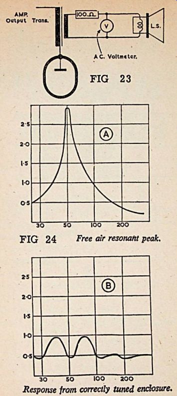
Tuning can only be considered accurate when the two peaks arc of equal amplitude and are equally displaced on either side of the free air resonant frequency originally measured.
By closing off part of the port opening it will be found that it is possible to vary the amplitude of one peak against the other. Port area should be artificially reduced until the conditions of correct tuning are approximated, port size can then be made permanent (See Fig. 24A and B). See Page 93.
CRITICAL DAMPING
Obtain a 4.5v torch battery and some cloth the latter to be of similar texture to that exhibited by cheap handkerchiefs. Connect one side to the battery to the loudspeaker, make provision for easy connection and disconnection for the remaining side. Make and break contact.
A sound resembling a “bing and bong" will probably result. Connect a single layer of cloth tightly across the port opening and repeat the test.
Continue adding layers of cloth and repeating the test until both "bing" and “bong" have been reduced to "click" and "click". Make sure that both “bing" and 'bong" have gone, one may disappear before the other but do not add more layers of cloth than necessary because over damping will cause inefficiency.
Critical damping properly carried out will ensure that the loudspeaker system is free of undesirable transient generation.
CROSSOVER FILTERS
Most readers will appreciate that a single loudspeaker unit cannot satisfactorily cover the entire audio spectrum. Usually two or more speakers are used and the audio spectrum is spilt up between them by means of an LC network commonly referred to as a crossover filter. Such a filter is normally situated in the speech coil circuit (or reasons of convenience and adaptability. It is possible to use an electronic crossover network at the front end of the audio system and two separate amplifiers.
This system is superior to the first method but of course, more costly.There are a number of low impedance networks suitable for Inclusion in the loudspeaker circuit perhaps the most popular are the quarter section series and half section parallel. Figs. 25 a and b show circuits and component values for both of these types.
Method of operation is simple to understand, the capacitor reactance increases as frequency is lowered, therefore, a capacitor in series with a speech coil will attenuate low frequencies. On the other hand,, a parallel capacitor will pass low frequencies but attenuate higher frequencies. The effect of the Inductance is the reverse of this. From this it will be apparent that the response of a given system can be adjusted to almost any requirement. Power loss with either circuit of Fig. 25 is not serious, about 1 dB for the quarter section and 2dB for the half section.
Both networks of Fig. 25 are designed for 15 ohm loudspeaker units and for a crossover at 2000 cycles. It is a simple matter to change the crossover frequency or to make the units suitable for loudspeaker units of lower impedance. Divide 15 by the voice coil Impedance of the loudspeaker unit to be used and multiply all L and C values by the quotient. If It is required to crossover at a different frequency and the crossover point is lower than 2000 cycles, divide 2000 by the required frequency and multiply all C and L by the quotient. Should the cross over frequency be above 2000 cycles divide the crossover frequency by 2000 and divide all L and C by the resultant. Conversion to a three speaker system is quite easy. A high frequency dynamic tweeter is fed via a high-pass filter consisting of a 2 mfd. capacitor across the existing treble unit.
In practice the capacitor is wired in series with the tweeter and the combination wired in parallel with the existing treble unit. With such a system It is easy to obtain an overall response from 20 to over 17000 cycles. Capacitors for crossover units should normally be of paper construction, use of electrolytic components can under certain conditions Involve considerable power loss. See Page 94.
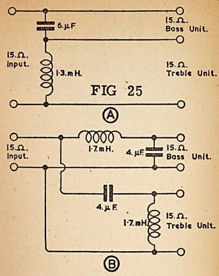
Coils or Inductors are normally home constructed and air-cored. For the Inductance values quoted in Fig. 25 their resistance should not exceed 0.6 ohm Mr. G. A. Briggs in his excellent book "Sound Reproduction" has given useful Instructions for constructing air-cored coils and the original coils for both filters in Fig. 25 were based on Mr. Briggs recommendations. Coils were wound to the following specification, 18 swg cotton covered enameled copper wire, 1" dia. wooden former provided with end cheeks, 32 turns per layer. For a 1.3mH Inductor 265 turns are necessary the 1.7mH coil will need 300 turns.
If Inductances of 2.6mH or 3.4mll are required, turns necessary are 365 for the former and 410 the latter.
It is not claimed that these specifications will provide the exact theoretical inductance required but errors of 10% are not serious with crossover networks and coils wound to the above specification are in use by the author.
PHASING LOUDSPEAKERS
"Phasing" is concerned with the utilization of two or more loudspeakers in such a way that the sound from any one loudspeaker does not cancel the sound from other units thus creating a dead area between them. This is an Important consideration where loudspeakers face the same direction. Connections to the voice coils, whether series or parallel, must be made in such a manner that at any one Instant all diaphragms are moving in the same direction.
If two driver units arc connected to a single horn It can be clearly understood that, If our of phase, the resultant pressure where the sound of the two units meet in the Horn would be completely cancelled and no sound would result. For parallel operation, the like terminals of each unit must be connected together, but If the loudspeakers are wired in series, two unlike terminals must be used as a junction . In-phase connections can be checked very easily, all that is required is a torch battery. Temporarily, wire up the loudspeaker in the manner to be used for final operation, i.e. series or parallel. Connect the terminals of the torch cell to the resultant two leads, a click will be heard and the cones will move in or out of the gap. Connections to the loudspeakers must be so arranged that all cones move in the same direction.
Phasing is of least importance where two loudspeakers are some distance apart or pointing in opposite direction, as the loudspeakers are brought closer together in small angular relationship, the necessity for in-phase operation becomes increasingly important.
Now it is very important to note that one class of loudspeaker unit is definitely excluded from the above remarks: the high-frequency tweeter.
Firstly, the question of phase is of no importance at the frequencies handled by this class of unit. Secondly, the application of a battery across a tweeter would not produce any noticeable movement but the unit might well be ruined. Briefly, phasing is only Important when low frequencies are being considered.
What is Genuine. Pseudo and Quasi Quadrophony?
And what also goes by that name Quadrophony - a new technique or a promotion stunt by smart publicity people? This is a question which is being heatedly discussed by music enthusiasts everywhere in the two years since tills term came Into acceptance in the 'High Fidelity world". Quadrophony, claimed by its Inventors to be "the perfection of music reproduction", reached the European continent almost simultaneously from the U.S.A. and from Japan.
"Four channel reproduction technology; quadrophony, now converts your living room into a real concert hall. The filling of your room with sound from four loudspeakers, one in each corner, gives one the fascinating impression of sitting in the middle of the orchestra" -- may be read in the advertising brochure produced by a well-known manufacturer. But what is this new technology in actual fact? A retrospective look at the almost 100 years of history of the record and apparatus Industry enables the development to be seen.
As is known the phonographs constructed by Edison in 1877 were the beginning. A metal foil-covered roller was the first acoustic sound carrier, which was further developed ten years later by Emil Berliner to a waxed, circular zinc plate - the forerunner of the present day record. The shellac record arrived at the beginning of the 1920s and was noted for its fragility and Its comparatively heavy weight. Nevertheless, this sound carrier lasted for around 30 years until It was replaced by the synthetic record.
However, a new development soon came on the scene: whereas up to 1959 exclusively monaural, i.e. one channel records could be manufactured, in Frankfurt, Germany, at the radio and T.V. exhibition held at that time the first stereo, i.e. two channel records were Introduced. A sensation for the professional world and a new kind of listening experience for music enthusiasts. On the occasion of the 1963 radio and T.V. exhibition in Berlin the "Sender Freies" Berlin radio station transmitted a program in stereo for the first time (using the pilot sound procedure), which was received enthusiastically by the majority of those in possession of the right equipment.
Further Developments in Stereophony in the middle of the 1960s - again an import from the U.S.A. - high fidelity technology found its way onto the European market. Experts worked out the technical data for the individual apparatus groups which, after years of preparation, found expression in the international quality standard DIN 45 500. These standards, developed by German Industry, have been the subject of world wide Interest. The view appears Justified that they will achieve recognition in the regulations of the International Electrotechnical Commission (IEC).
In the meantime, a new development has taken place of Importance to both the record and to play back equipment: Quadrophony.
The first attempts at a theoretically worked out basis of four channel recording converted Into an acceptable sound extend back to 1970. Quadrophony can be more or less regarded as a further development of two channel stereo, which after some years of being regarded in a skeptical light by listeners can demonstrate Its great advantages to all.
A Technical Trick , Nevertheless -- in stereophony there are two different procedures; first we have pseudo-stereophony, in which the sound emitted into a room comes through a mono channel over several loudspeakers. The acoustic reproduction creates a "spatial" feeling - contrary to monophonic (also called monaural), reproduction, in which the sound radiation is also achieved over one channel but whereby only one loudspeaker is used. One talks of genuine two channel stereophony when the sound radiates from two different channels, Installed on a stereo basis. Proceeding from this two channel technique technical experts developed four channel recording, termed quadrophony. Additional sound information is Included in the grooves in such a way that the wave trains are no longer vertical to the groove axis, as was previously the case, but are now inclined at an angle. With the aid of a coder four channel recordings can be converted into a two track sound signal. This two track signal is reconverted from the receiver side by a decoder back Into its original four signals. This technical trick makes a separate sound omission possible from four channels through four Independent loudspeakers.
Not all procedures are "genuine".
----
At present the argument as to which is the best system is a matter of opinion. For even in expert circles quadrophony is regarded in varying lights, the more so because the systems known at present have not completely left the development stage yet. At this moment in addition to the pseudo and quasi quadrophonic reproduction there is a choice of two "genuine" quadrophonic procedures, which ought to characterize the rapid development of this technical Innovation best. The individual procedures differ roughly as follows: -
Pseudo quadrophony branches certain information from the right and left channels, which is emitted through two additional loudspeakers.
Quasi Quadrophony
This is a definite further development of pseudo stereophony. With this system new signals are formed out of the right and left channels.
The engineers responsible for development differentiate between five different types in this group along (quadro-sound, analyzer, Hafler, 4D and multi-sound).
The main difference between these two procedures and that of genuine quadrophony is basically that in addition to the four reproduction channels there are also four separate recording channels. With the first procedure of this type, the matrix system, the four channel recording is encoded onto two channels and, on the receiving side, decoded again into four channels. Within this system there are different types too, SQ, QX, X4 and QS, but space does not allow us to go into more detail.
The other "genuine" one of its type is the discrete quadrophony. Whereas with discrete four track tape reproduction no special technical measures are necessary, in the case of discrete record reproduction the four channels must be converted by the multi-flex process via subcarriers and for the actual reproduction it must be led back to the original four signals.
Thus, with the corresponding investment of times and materials the higher values for the separation of the channels is achieved.
Still No Broadcast Quadrophony
It is Important for music enthusiasts to know that all music reproduction equipment suitable for stereo records is equally suitable for matrix quadro records. With regard to the distortion, noise and interference ratios there is no difference in the reproduction of quadro records. On the other hand a compatibility exists so that stereo records can be played over four channel equipment. So far as can be seen the financial cost of matrix quadrophony ought to remain within a reasonable range, making quadrophony available to a wide cross section of buyers. Quadrophonic broadcasts, however, as has been stated by the broadcasting authorities, are unlikely to come into being in the foreseeable future.
Nobody, from among the ranks of the experts, will be able to forecast which quadrophonic system will become established. It will be the world market which decides this.