Most transmission line enclosures involve a lot of tricky woodwork so that many speaker builders with only modest woodworking skills are deterred. With the Kapellmeisters, although quite a lot of woodworking is needed, none of it is difficult, mostly it consists of cutting straight edges. These MUST be straight though, so if your saw cuts tend to wander, get the timber yard to cut them for you. The measurements are uniform with many pieces being identical; this helps a lot in the preparation.
Use standard 8 x 4-inch ceramic tiles, cut down to 7 x 4 inches. That is just one straight cut per tile. The exception is the top tile over the speaker which because of its different angle must be narrower, 7 x 3+ inches.
Triangular blocks are used to support the tiles as shown.
These are made by first cutting 4, 3-inch squares, then sawing diagonally to give 8 triangles. The two blocks for the over-speaker tile are made by halving a 3 x 2-inch rectangle. A standard 3 x 1 mix of sand and cement is used to fill the space behind the tiles. In some cases the cement is applied first between the blocks and the tile bedded on to it, but in others the tile is fixed first to the blocks and the cement applied at the back afterward.
In all cases screw two or three stout screws at random angles into the wood where the cement is to be laid leaving about an inch out of the wood, so that they will be buried in the cement.
These will then secure the concrete block in place when it is dry. Thoroughly wet the back of the tile before applying it to the cement. In some cases the front of the tile may need to be held in place while the cement sets, with panel pins knocked into the wooden sides. It does no harm to leave them there afterward.
All jointing is done by a strong wood glue. Evostik wood glue was used for the prototypes which is very strong and convenient to apply. It also fills any small gaps where the saw might have made a slight error. If not available, a substitute will have to be used, but make sure it is a wood glue not a general purpose adhesive. Construction must proceed in numerous stages to allow the glue and concrete to set before continuing with the next, so some patience must be exercised.
Make both speakers at the same time so that each stage can be completed on both and thus save time.
First Stage
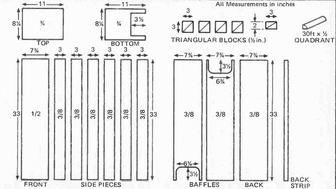
First, consult the diagram of wood panels (Fig. 42), and buy sufficient plywood for all. Remember that these are for ONE speaker, so each will have to be duplicated. As so many are just 3 inch strips, it is likely that much can be obtained as off-cuts. Most large timber merchants sell these at a reduced rate, and the color or grade doesn't matter as all are concealed except the top and bottom cheeks. The thickness should be as specified 1/8-ths for the sides, baffles and back, 1/4 inch for the front, and ¾ inch for the cheeks. It really will save a lot of time and energy if you get the merchant to cut the pieces with his machine saw.
He probably will not do the shaped lugs at one end of the baffles and bottom cheek, but this can be managed with a fret saw. It is the most difficult part, except the elliptical hole for the speaker, and fortunately, if the cut is a bit rough it doesn't matter very much. A 7.25 x 4.25 elliptical speaker hole should be cut in the front panel starting 2.25 inches from the top. It is desirable though not essential for the hole to be beveled outward.
Second Stage
Having cut the pieces, we start with the front panel. Lay it face downward supported on some scrap quarter-inch ply or hardboard. Glue the top and bottom edges and fit the top and bottom boards. The front edges of these should NOT rest on the ply supports but directly on the work surface; they will thus protrude a quarter of an inch beyond the panel. They should also be positioned to give an equal overlap at either side. The idea is for the top and bottom cheeks to overhang the front, sides and back.

Fig. 42. View of all wooden parts for one speaker. Note that each side
is in three parts, thus requiring six identical pieces for the two sides.
All pieces should he of plywood.
Weights should be applied to the free sides of the cheeks to hold them against the panel while drying. Measure the distance between the rear edges of the top and bottom cheeks to ensure that it is exactly 33 inches and therefore the top and bottom are parallel. Wait for glue to set and harden.
Third Stage
Next, fit the first pair of side pieces, gluing the ends and the edge contacting the back of the front panel; ensure the pieces are flush with the edge of the front panel. Measure across the upper edges to make sure they are 7.75 inches and so are true.
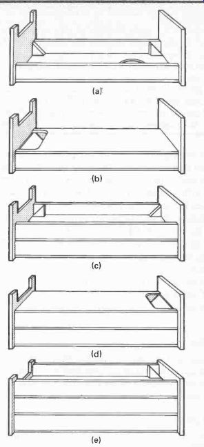
Now glue the triangular blocks in place at the bottom and top as shown in (a) of Figure 43, the top ones being the special sized ones. Glue the edges as well as the face that contacts the sides, but be careful in pressing them into place that you do not move the sides. Wait for the glue to set.
Fourth Stage
Now fit the speaker, screwing it place over the aperture, and connect by soldering, a pair of wires which are run down the panel to a hole drilled in the bottom. Leave a few inches free, and make sure both speakers are connected the same way to the color-coded wire. It is prudent to cover the front of the speaker with a piece of card secured by drawing pins to protect the cone during subsequent operations.
Fit several screws to the bottom and top cheeks between the triangular blocks, leaving about an inch protruding at different angles. These will be embedded in the concrete when it is applied and so will hold the resulting concrete wedge in place. Next fill the space between the bottom blocks with cement (not too wet) and bed the tile onto it. Place the top narrow tile on the blocks and fill in behind it with cement.
Allow time to harden; if desired a quick-drying additive can be used to speed matters up.
Fifth Stage
Saw suitable lengths of quadrant and glue into the corners between the front panel and the sides. It they are warped they should be held in place with panel pins. Glue two further strips of quadrant at the top inside edge of the sides and pin to secure.

Fig. 43. (a) First stage in construction. The front is glued to top and
bottom cheeks, using 3/8 in supports to lift front into correct position.
First pair of side pieces fitted and triangular blocks (small ones
at the top) in position. Apply concrete, fit tiles and lay wadding. (b)
Fix first baffle, gluing and pinning down to ensure close fit. (c) Fit
second pair of side pieces and four triangular blocks (all blocks from now
on are regular size). Apply tiles, concrete, and wadding.
Tuck two extra lengths of wadding through aperture into first channel. (d) Fit second baffle gluing and pinning. Aperture goes at the top. (e) Glue in third pair of sides and last pair of blocks. Fit tile and concrete, lay wadding and fit back. Double an extra length of wadding around the ends of the full lengths. Sand down, fill crevices, finish top and bottom cheeks, fit fabric and fix legs.
Cut three lengths of BAF wadding to size and lay them in the cabinet so that two start at the bottom of the speaker, and the third lies over it to the top of the case. Fill the space above the speaker with a rolled up piece of wadding. Make the lengths a few inches longer so that they bend up at the bottom over the tile. The three layers will fill the channel without compression.
Now fit the first baffle with the cut-out at the bottom, gluing to the top edge of both the sides and the upper quadrant surface. Also glue to the top and bottom cheeks.
Secure with panel pins to ensure a close fit as (b) in Figure 43.
Next, fit the second pair of side pieces and two pairs of blocks top and bottom, (see c). Fit quadrant to corners as with the first channel, also to top edges of the sides; wait for all the glue to dry.
Sixth Stage
Fit the tiles and cement as with the first pair, not forgetting to fit the securing screws to top and bottom cheeks in the area to be filled with concrete. This time the top one will be bedded and the bottom one rear-filled. Wait for concrete to set.
Seventh Stage
Cut two pieces of wadding about 18 inches long and push half the length of each up the lower channel through the cut-out, and lay the other half length back along the top channel. Now lay three full length strips over these along the complete upper channel. This gives the extra density at the first bend needed to dampen the third harmonic antinode.
Next comes the second baffle which is glued and pinned as the first but with its cut-out at the top as shown at (d). Fit the third and final pair of sides, also the last pair of blocks plus the quadrant in the corners and top edges, see (e). Allow glue to harden, Eighth Stage Now for the last tile, again not forgetting the screws in the top to secure the concrete wedge. Mount the tile on the blocks using panel pins to keep it in place; this will be easier if the enclosure is stood vertically upside down. Return to the horizontal, and fill in rear with cement. Wait until set.
Ninth Stage
Lay three strips of wadding in the channel making sure the bend is filled. Put some extra here if necessary to fill completely. Cut another strip about 24 inches long and tuck half the length under the other three at the outlet, and bring it over the top so that it covers the rough ends. Lastly glue and pin the back in place.
Tenth Stage
Now for the finishing. Sand down any ridges in the sides, but do not be too fussy, for they will be completely covered with fabric. Check carefully for any cracks or crevices in the jointing and fill with the wood glue. Sand, then stain or varnish the top cheek and the edges of the bottom one, there is no need to do underneath unless you are fussy. Paint the body with matt black including the inside rim of the loudspeaker aperture, but be very careful not to get any paint on the loudspeaker cone as this would affect its flexibility. The painting ensures that the bare wood does not show through the fabric with which the whole body excluding the cheeks is covered.
The two back strips (one for each speaker) should now be cut to fit exactly between the top and bottom cheek rear overhangs. These strips conceal the join in the fabric covering so should be about I inch to one inch wide preferably beveled at both edges to give a good finish. They should be stained or varnished the same color as the cheeks.
Eleventh Stage Obtain sufficient black speaker fabric to cover both speakers.
Any other color can of course be used if preferred and is obtainable.
Cut the fabric to the exact size to cover the body between the cheek overhangs, but leave a flap 4 inches longer and 8-inches wide, at the start. Secure the vertical starting edge at one edge of the back of the enclosure with tacks so that the flap hangs over the bottom. Then pull it around, keeping it taut, overlapping the start and securing it with one of the wooden strips down the middle of the back. This can be done with brass countersunk screws with cupped washers which give a professional-looking effect.
Next trim the flap to fit between the prongs of the bottom and fix it across the exit port with gimp pins.
Twelfth Stage
Make a pair of 2-inch high legs similar to those shown in the side-view illustration in the last section. A single rear one should be made to incline backward under the rear exit vent to give greater stability as in the illustration. They can be stained or varnished to match the rest. Pack filler around the hole in the bottom through which the speaker wire passes to make it airtight, and fit a connecting block underneath.
The Kapellmeisters are now complete and ready to go into action. So what sort of performance can be expected? Technical and listening tests were made on the prototypes and the following section describes the results.
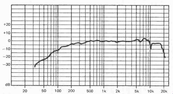
Performance As an anechoic room was not available, frequency response tests were made by means of the multiple microphone position technique. They were repeated on the second speaker in a different position, and the results were very close, so the plot reproduced here can be considered accurate (Fig. 44).

Fig. 44. Kapellmeister frequency response.
Surprisingly, the treble response is sustained beyond 16 kHz and actually continues up to 20 kHz, a remarkable achievement for a single driver speaker with no tweeter. This is a tribute to the controlled flexure of the cone and the effectiveness of the high-frequency horn. The undulations are fairly smooth, and some of the vicious peaks and dips encountered with certain multi-driver speakers are notably absent. The response is within 5 dB from 16 kHz to 200 Hz, apart from small deviations at 7 kHz and 10 kHz, There are of course no phase problems over any part of the range.
As expected, the bass is not sustained with a flat response to as low a frequency as would be obtained from a large infinite baffle or reflex enclosure. The response crosses the- 5dB level at 200 Hz and from there a very gentle descent, but audible output is maintained down to around 36 Hz, which is lower than the design brief. Actually, there is a 3 dB drop in the octave 500- 250 Hz, a 6 dB drop from 250- 125 Hz, and a 12 dB drop from 125- 62 Hz and below.
This gentle and gradually increasing slope results in a more natural and musical bass than when the roll-off is lower, but steeper. A further advantage is that this curve is ideal for applying a little bass boost at the amplifier. All bass boost controls hinge the response curve upward from a pivotal point at 1 kHz. Frequencies just below 1 kHz are hardly affected, but the amount of boost increases as the frequency drops. If bass is boosted with speakers having a steep roll-off, the frequencies just above the roll-off point are lifted to produce a hump, so resulting in a boomy effect. Here, bass boost will lift the curve to give a flatter response without boom.
Thus with a little boost in the bass, the single driver in an enclosure only 8 inches wide can be made to give a response equivalent to that of a much larger multi-driver speaker, but without the phasing problems and distortions they and the crossover network produce.
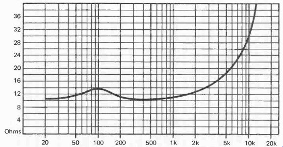
The impedance curve is also of interest and is here shown (Fig. 45). There is no large peak in the bass, just a small rise at 100 Hz, which is at the third harmonic of the transmission line resonant frequency.

Fig. 45. Kapellmeister impedance chart.
Bass peaks indicate a high back EMF generated by a large cone movement at the resonant frequency, even though the acoustic output may be damped by the cabinet design. Often these excursions may be large enough to enter the non-linear region or even strain the cone suspension. In such cases bass boost should be applied cautiously and moderately if at all to avoid speaker damage, quite apart from causing a hump in the response as noted above. Here, having no impedance peak, there is no excessive cone excursion at any frequency and no such restraint is necessary. Bass boost can thus be applied to obtain a satisfactory balance without fear of damage, providing the speaker's power rating is not exceeded.
At the high frequency end, the impedance curve gradually rises to 60 12 at 20 kHz. This is not due to increasing cone movement but the increase of the coil reactance with frequency. This means that less power is being taken from the amplifier at these frequencies. As amplifier distortion often decreases with an increase of load impedance, this should present a very 'easy' load for any amplifier, and there should be none of the unexpected problems often encountered when an amplifier takes a dislike to a particular speaker. Nowhere does the impedance fall below 10 12 Sensitivity is 90 dB for 1 watt input at 1 meter. This is higher than average and enables an amplifier of just a few watts to be used. Five watts per channel should be sufficient and well within the speaker's eight watts rating, although up to eight watts can be used for the larger listening room. This affords the opportunity to use a class A amplifier which can easily be designed for low powers such as these.
Listening Tests
Technical measurements can tell us a lot about how a speaker should sound, but they are not infallible. Some speakers that measure well sound dreadful, while others that appear unexceptional in the tests perform very well subjectively. Much of this is due to the effect of the speaker and its crossover network on the amplifier feedback circuits, unpredictable until you actually try them both together. With the Kapellmeisters of course there are no such problems Listening tests with the Kapellmeisters operating with a little bass boost confirmed all hopes. The results are not `spectacular', so those looking for thump, blast and tizz would be disappointed. Instead, musical instruments sound as if they are musical instruments. Nonetheless there is plenty to excite the ear in full-blooded orchestral climaxes.
Ambience and sense of presence was perhaps the first noticeable effect, Woodwind was clear, easily identifiable and rounded in tone. Brass was brilliant yet mellow, staccato passages really were staccato, not slurred as they sometimes sound. A recording of a harpsichord was astonishing, revealing tones and subtleties never heard before, it really sounded as if was right there between the two speakers. A solo violin sounded natural with no moments of discomfort in the higher passages. One passage in an orchestral work that always sounded as if it was performed by the 'cellos playing pizzicato, could be clearly identified as played on the lower registers of a harp.' Cellos sang, not grunted and rasped. Many recordings were really heard for the first time.
The coherent phasing and narrow sound source had their expected effect on stereo imaging. An unconventional instrumental positioning employed by a renowned foreign orchestra was instantly noticed during a stereo broadcast.
Stereo broadcast drama proved quite dramatic, with positive locational identification even in crowd scenes.
The 'hole-in-the-middle' effect whereby all the sound comes either from the left or the right and none from in between, is often obtained when the listener is too close to the line between a pair of speakers. This has not been experienced at all. In fact, listening actually on the line with the speakers on either side produces a rock-steady central image apparently right in front of the listener's face. As with most speakers the most consistent stereo effects are produced with the speakers turned slightly inward.
There are a couple of drawbacks though. One is that after becoming accustomed to the Kapellmeisters most other speakers sound rather boxy or muddy in comparison, so they rather spoil one's enjoyment of music when heard on other systems! The other snag experienced was that a large collection of recordings that formerly were considered acceptable, soon became divided into those that were really excellent, those that were reasonable, and many that were poor. The excellent qualities of the first group and the bad ones of the last had been concealed by the previous speakers. In common with all good speakers, the Kapellmeisters show up faults in the program material as well as bringing out the best in it. So be prepared to replace some of your recordings.
How Much Bass Boost?
As noted previously the response is improved with a little bass boost, but not too much. It is not easy to make an accurate adjustment with music; with the price of concert seats as they are, few of us are all that familiar with the real thing.
A better test is something we hear every day, the human voice, and in particular the female voice. Why female? Because we naturally expect bass sounds in a male voice so if we apply too much bass it may not be noticed. Tune to a f.m. radio station broadcasting a female voice, then advance the bass control slowly from the flat position. The first effect is a fuller tone which sounds pleasing and natural, but soon bass `chesty' tones will be heard which are not. Turn the control back a point from here and you will have the optimum position. Having established this you will find it gives the most natural effect with the male voice and music, thereby confirming the setting.
Treble Boost
Treble boost should not be needed unless you have thick carpeting, plenty of well-padded furniture and in particular a large area of curtaining. The latter is the factor having the greatest effect. Even then, boosting should be very limited as too much gives a hard tone which may seem bright and crisp to start with but soon produces uncomfortable moments and listening fatigue. The Kapellmeisters need very little, if at all.
Paradoxically, the best test is the male voice, which contrary to popular expectation, has more high-frequency content than the female. The reason is that although the female has a higher fundamental tone it is purer, with fewer harmonics than the average male.
Tune to a broadcast of a male speaker and listen for the consonantal sounds ch, t, d and s. Slowly advance the treble until these are heard distinctly, but naturally with no exaggeration. Any tendency to lisp shows you have gone too far.