Today we take the complex innovations of radio and television largely for granted. But it took many years and the work of countless people to develop our present system of broadcasting. Perhaps we should stop right here and explain what the term broadcasting means. Broadcasting was originally a farming term that meant spreading seeds all over the field. In radio and television, broadcasting means sending out programs through the air to everyone within reach of a station. Anyone who has the necessary equipment can listen to the programs sent out.
Some of the countless people interested in broadcasting had commercial or military interests, while others experimented with the new medium purely from academic or avocational interests. Without the work of these inventors, radio and television would not have been possible. They discovered ways to transmit coded messages, which was important to ships at sea. It was not until engineers discovered how to impress voices and music on wireless, however, that radio became popular. As industry discovered the economic potential of broadcasting to homes, a great interest in the work of these engineers developed.
This section examines how radio and television work and how the broadcast channels are divided among the various services--AM, FM, and television.
OSCILLATION
To understand radio waves clearly we must first understand the electrical impulses that create radio waves and that means exploring the concept of oscillation.
Electricity may exist in at least two forms-direct current (DC) and alternating current (AC). To understand the difference between the two, the system in which electricity flows must be examined. All such systems are closed. This means that one may start at any point and by traveling in one direction eventually return to the point of origin. Figure I-1 shows a typical circuit.
The generator pushes minute, electrically charged particles called electrons through the circuit, much as a pump pushes water through a hose. This genera tor may be a battery such as one finds in a car, or a giant atomic energy plant used by electric companies. The light bulb uses up the energy of the electrons pushed through the circuit.
If the generator pushes the electricity in only one direction, we call this pat tern of electric flow direct current (DC). DC is the kind of electric flow with which batteries, such as those in cars or flashlights, operate. When electricity flows in only one direction, all of the electricity stays in the wire and, therefore, no electrical field is created around the wire. On the other hand, if the electric flow first surges forward-we shall call this the positive direction-and then reverses itself and moves backward-let's call this the negative direction-then the current is oscillating and is often called alternating current (AC). This pat tern of electrons first rushing forward and then backward can be compared to the motion of a yo-yo. First the yo-yo races down the string, in what we might call a positive direction, only to reverse itself and race back up the string in the negative direction. AC is the type of electric flow found in the wires of one's home.
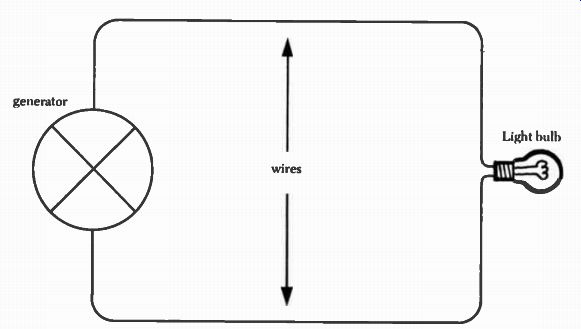
Figure 1-1. Diagram of a simple electrical circuit. The generator pushes
the electrons through the wires so that the light hull) can use the resulting
energy to produce light.
We can diagram this alternating flow of electricity as shown in Figure 1-2.
The horizontal line represents the amount of time that has elapsed and permits us to measure the amount of time required for one cycle, or one forward and one reverse motion. The length of time a cycle requires is sometimes called its period. The segment of the graph above the horizontal line represents the electricity when it is flowing in a positive direction. Then, as the electricity reverses itself and flows backwards, the graph goes below the horizontal line to indicate the negative flow of electricity. One full oscillation has been completed when the forward and reverse surges have ended.
Characteristics of an Oscillating Current
When an alternating current flows through a wire, some of the energy escapes, or radiates, into the area around the wire. With the right instruments, it is possible to pick up this energy. All alternating currents radiate some electrical energy. In fact it is this radiated electrical energy that radio stations transmit that enables us to hear our favorite programs.
Frequency
We call one complete oscillation a cycle. Electricity, like a vibrating reed or violin string, oscillates a certain number of times per second. Ordinary household current oscillates at sixty cycles per second. Radio waves oscillate much faster. We describe the location of a radio station on the radio dial (or on the radio spectrum) by the number of cycles per second at which the radio carrier oscillates. For convenience radio people have chosen to shorten the term cycles per second- to Hertz (Hz) after the German physicist, Heinrich Hertz, who conducted some of the early radio experiments.
The number of Hertz a station uses is called its frequency. Thus if a certain station operates on a frequency of 980,000 Hz it is possible to determine its location. But if you examine your radio dial, you will discover that no number as large as 980,000 appears on it.
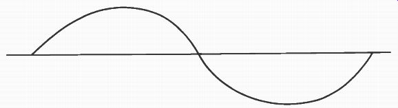
Figure 1-2. Diagram of the flow of alternating current. The top half
of this graph represents the positive flow of electricity, while the
part below the line represents the negative flow.
Because many radio frequencies are very high, (the highest are near 3,000,000,000,000 Hz) engineers have developed a numerical shorthand to refer to them.' The word kilo means 1,000; mega refers to 1 million; and giga means billion. By combining kilo with Hertz to form kiloHertz (kHz), we can now refer to the frequency of the 980,000 Hz station as 980 kHz. Or we could use the prefix megaHertz (mHz) to say that the station has an operating frequency of .98 mHz. When a dial for a new radio is printed, the prefix which makes the numbers on the dial easiest to read is used.
Waves
Although we will discuss radio signals as waves, a modern branch of physics theorizes that radio signals are actually quanta or bursts of energy sent through the air. The wave theory regards radio signals as continuous waves of energy while the quantum theory regards radio signals as bursts. In our discussion we will think of radio as a wave and we will examine this most closely. It is important, however, to remember that both are theories used to explain a concept that we can only partially understand at present.
Radio waves emanate from a transmitting antenna very much as waves radiate from the point at which a rock falls in still water. The waves of water resemble the diagram of a cycle in Figure 1-2. Water waves have hills and valleys that correspond to the high and low points in a radio wave. Further, the water waves radiate from the rock in ever expanding circles. In just such a way radio waves emanate from the radio tower. Of course radio waves travel in all directions--up, down, horizontally--while water waves appear to travel only across the surface of the water.
Just as an ocean wave can be modified or stopped by a rock or beach, so radio waves can be modified or stopped through contact with mountains or buildings. You may have watched a wave encountering a pier or other solid object and then seen the wave reflected by the object back towards its source.
Similar things happen when radio waves hit solid objects. This is why we some times see two images of a television picture on our screen. The second image is the result of the reflected wave reaching our television set.
Most radio signals radiate out from the radio tower in a circular pattern just as the water waves radiate in a circular pattern. Sometimes stations use several radio towers arranged in a straight line. When this is done radio waves radiate in a figure eight pattern as shown in Figure 1-3.
Wave of different lengths behave differently and can have an important impact on how radio waves travel. Long waves at low frequencies-below the AM broadcast band-tend to travel long distances and will bend around the earth.
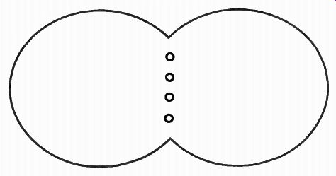
Figure 1-3. Pattern of radiation for directional station. The figure
eight pattern of a directional station is the result of the special arrangement
of multiple towers and the way radio waves are fed to each tower.
Medium-length waves travel around the earth somewhat but will not travel as far as long waves, and short waves-those above the broadcast band-will not bend around the earth and are dependent upon waves that are reflected back to earth by a band of electrically charged particles, called the ionosphere, that surrounds the earth. However, very short waves are not bent back to earth but pass through the ionosphere and consequently can be picked up at only short distances from the transmitter.
This behavior of radio waves can be understood by an illustration involving light, which is a radio wave. When a beam of sunlight passes around a sharp surface such as a thin key, the key tends to bend the light waves slightly so that the light waves, which were traveling parallel before reaching the key, are bent slightly and no longer travel parallel. Thus the image of the key on a wall will be somewhat fuzzy. (See Figures 1-4 and 1-5. )So long as the thickness of the key is less than the length of one wave, this bending will occur, but when the thick ness of the key becomes greater than the length of a wave, then it is unable to effect any bending.
Rays of light
Small object in the path of parallel rays of light
Screen or other target upon which light rays fall
Sun or other distant source of light
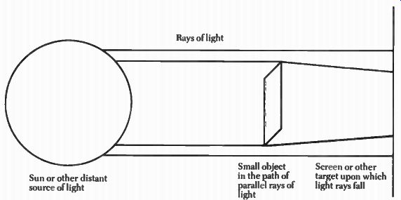
Figure 1-4. When rays of light impinge on the edge of a thin object
like a sheet of paper or a key, they are bent slightly by the object
as is noted by the two lines representing rays of light that touch the
object above. Notice how they converge towards each other while the two
lines representing rays of light which do not touch the object continue
in a straight path. As long as the wavelength of any wave is longer than
the thickness of an object with which it comes in contact, the object
will bend the wave somewhat.
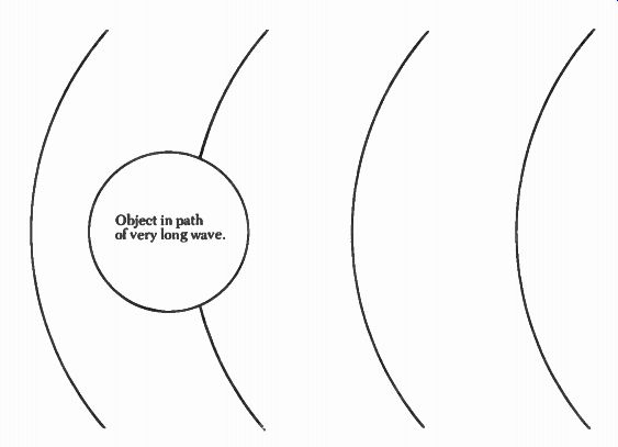
Figure 1-5. Peaks of waves. When one drops a rock in still water waves
flow out from the point of impact as shown by the partial circles above.
If the waves are much longer than the object is thick, then the waves
will flow (or bend) around the object as shown above almost as if the
object were invisible to the wave.
Both ocean and radio waves have a length, which is called their wavelength.
Wavelength represents the distance from the beginning to the end of one complete cycle. As the frequency of a radio wave increases, the length of the wave decreases. Thus, very high frequencies have short wavelengths and much lower frequencies have long wavelengths.
The reason for this relationship between frequency and wavelength relates to the distance a radio wave travels in a second. All radio waves travel the same distance in one second; that is, about 186,000 miles. As the number of cycles crowded into one second of travel increases, each cycle must become shorter so that all of the cycles can be crowded into one second. The extremely long waves at frequencies below the standard broadcast band are sometimes several miles in length. A building, a tree, a hilltop, or a water tower are all relatively short compared to one wavelength and thus almost anything can cause these waves to bend. As a result, long waves readily travel around the surface of the earth.
When a wave clings to the earth it is called a ground wave.
As waves get shorter, the ability of the earth and other objects to bend them becomes less and so shorter waves tend not to follow the contour of the earth as well. This problem becomes pronounced near the middle of the AM broadcast band, with the result that lower frequency AM stations tend to enjoy the benefits of waves bending around the earth while higher frequency stations do not. Thus, some of the AM channels in the higher ranges depend heavily upon being bent back to earth by the ionosphere.
The ionosphere is thinner than most waves up to about 30 mHz and consequently does a pretty good job of bending radio waves back to earth up to that frequency. However, the ionosphere changes thickness from day to night and during different parts of the year, so it is impossible to name an exact upper frequency at which it will no longer bend waves. These radio waves that travel out through space to the ionosphere are called sky waves.
Radio waves above about 30 mHz can neither be bent around the earth by objects on the ground nor back to earth by the ionosphere. Transmitters operating above 30 mHz must depend upon a third type of waves for reaching receivers-line of sight waves. These line of sight waves travel straight from the transmitting antenna to your television or FM radio antenna. This is why television antennas are often placed on top of houses. The higher they are, the greater distance the antenna can be from the transmitter. Of course, tall buildings and other objects prevent these radio waves from reaching your antenna and so in large cities like New York many people complain about television reception problems.
Amplitude
Amplitude and the more popular term volume are the same. When you turn up the volume on your radio set you are increasing the amplitude of the sounds you hear. Amplitude can be understood by thinking of how one might play middle C on a piano. By hitting the key hard, one produces a very loud sound, by only lightly tapping the same middle C, a low sound is produced. The same note has been played, but the volume or amplitude has changed. Just as sound waves have amplitude, radio waves have amplitude and we have diagrammed the difference in amplitudes of two waves in Figure 1-6.
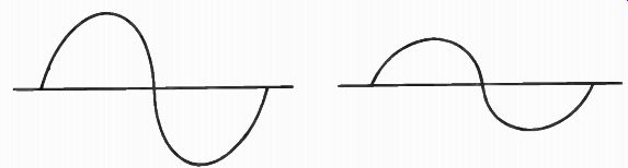
Figure 1-6. Comparison of two waves with different amplitudes. The wave
on the left has a much greater amplitude than the wave on the right.
Attenuation
As a radio wave travels through the air some of the signal is absorbed or lost in a process called attenuation. As a result, the radio wave gets weaker and weaker as one gets farther from the station until it is impossible to hear the station.
Let's return to our example of striking middle C. If we were to place a piano in an open field and strike middle C, we could hear the note clearly near the piano. But if we were to stand 300 feet from the piano, we would not hear the note as clearly. Finally, if we were to walk far enough away, we could not hear the note being played at all. This attenuation of sound waves limits the distance we can be from the sound source to still hear it.
All radio frequencies are attenuated as they travel through space; the very highest radio frequencies are absorbed very rapidly in the atmosphere. Of course there are other factors that attenuate radio waves such as rocks, mountains, and buildings. But, in fact, it is this rapid absorption of radio waves at the highest frequencies that limits the usable frequencies.
Electromagnetic Spectrum
Radio waves are only part of a much larger range of waves called electromagnetic waves. Electromagnetic waves include cosmic rays, X-rays, light, and radio waves. Thus, light waves and radio waves are both part of the same spectrum of electromagnetic waves. They differ only in the frequency at which they vibrate. The lower frequencies of the electromagnetic spectrum are occupied by radio waves that can send signals through the air. Just above the radio waves are infrared or heat waves; then come light waves, ultra-violet rays, X-rays, gamma rays, and cosmic rays. Figure 1-7 shows the distribution of the different kinds of waves.
The range of radio waves has been arbitrarily divided into subgroups for convenience. In the early days of radio only the lower frequencies could be used, but as equipment became more sophisticated higher and higher waves became usable. As noted earlier, the highest frequencies are absorbed almost as soon as they leave the transmitter so that, at present, the highest usable frequencies are about 3,000,000,000,000 Hz.

TABLE 1-1. Division of Radio Spectrum.
Source: Frederick Emmons Terman, Electronic and Radio Engineering, (New York: McGraw-Hill, 1955), p. 3.
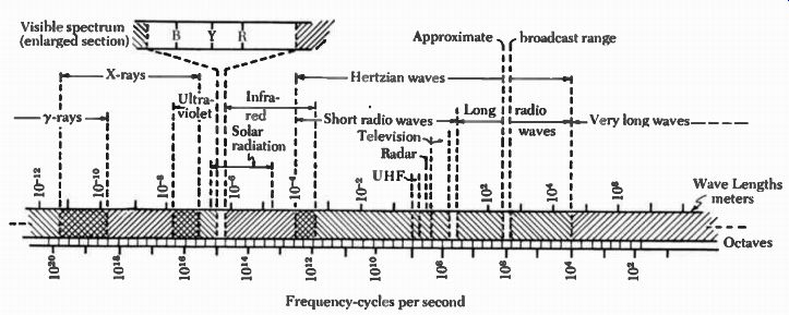
Figure 1-7. Wave distribution. Source: Donald G. Fink and David M. Lutyens,
The Physics of Television, Garden City, N.Y.: Doubleday and Company,
Inc., 1960, p. 30.
THE MANIPULATION OR MODULATION OF RADIO WAVES
No one would be interested in simply sending a radio wave out into the air without sending some information with it. In the earliest days, radio waves were turned on and off to transmit coded information. This on and off keying of a radio signal allowed experimenters to send the Morse code letter "s- across the Atlantic (1901). It allowed ships at sea to communicate with land, but code was of little interest to the general population.
Many wanted to impose voices, music, and pictures on the radio waves. The process of adding sounds and pictures to a radio wave is called modulation. We can draw a rough analogy between modulation and the function of a truck; that ...
--------------------
GALLOPING TECHNOLOGY
New innovations seem to be appearing at an increasing rate, for example, optical fibers. These fibers are small filaments similar to wires, but they conduct light rather than electricity. Light holds more promise for carrying many signals than does electricity. While cables and wires carry telephone and telegraph wires, the potential of optical fibers is so much greater than wires that picture phones may be a real possibility. The only problem is that AT & T has such a great investment in wire and cable systems that it is unwilling to adopt the new technology.
---------
---------
TYPES OF ENERGY
Scientists have found only a few different kinds of energy. The first was heat energy derived from burning coal, oil, and wood. Heat powers cars, heats homes, and keeps airplanes in the air. The second form of energy-electricity-lights homes and powers factories. The third form of energy, magnetism, has uses ranging from magnetic toys to powerful industrial machines. Electricity and magnetism often operate together as is the case in radio waves. The fourth source of energy, the atom, provides power for bombs and modern electric plants.
----------------------------
... is, our radio wave serves the same function as a truck in that it has no real use unless something is hauled. Indeed radio and television waves are often called carriers because they are used to carry pictures, music, sounds, and speech to the listener and viewer. When one thinks of a radio carrier as a truck and the sound, music, and pictures as the cargo, modulation is the process of loading the cargo onto the carrier. There are several methods for modulating a radio carrier, but three provide the major methods used by commercial broadcasters-amplitude modulation (AM), frequency modulation (FM), and television (TV). The first two provide only sound signals while the third, of course, provides both sound and picture signals.
Amplitude Modulation (AM)
The AM process of modulating a radio carrier is essentially one of varying the amplitude of the radio wave to conform to both the amplitude and frequency of the sounds one wishes to broadcast. This is much like using a water faucet to modulate a stream of water. A trickle of water corresponds to soft sounds, while water flowing fully from a wide open faucet resembles the effect of loud sounds on an AM radio wave. Thus, in AM, the sound wave works as a valve controlling the volume, or amplitude, of the radio wave forcing it to conform to the volume and frequency of the sound wave. The process of amplitude modulation is shown in Figure 1-8.
Size of an AM Channel. The process of modulating sounds on a radio wave requires a large band of radio frequencies. The actual number of frequencies is dependent upon the quality of sound one wishes to broadcast. The human ear can hear sounds whose frequencies range from a low of about 20 Hz to a high of about 20,000 Hz. If we wanted to modulate all of the sounds we are capable of hearing on a radio wave, our wave would have to carry sounds ranging from 20 Hz to 20,000 Hz. However, AM radio stations can only broadcast frequencies from about 100 Hz to about 5,000 Hz. 2 Although this limited range includes voices and most musical instruments, it does not include many complex nuances of music that make for "high fidelity" reproduction.
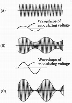
Figure 1-8. Diagram of radio wave modulated by AM. Source: Doug DeMad,
ed., The Radio Amateur's Handbook (Newington, Conn.: ARRL, 1970), p.
235.
To broadcast the sound frequencies between 100 Hz and 5,000 Hz, an AM station must have a band of radio frequencies that is 10 kHz wide. When an announcer tells you that a station is operating on 600 kHz, only the center of the station's channel is being described. It actually extends from 595 kHz to 605 kHz.
The AM Broadcast Band. Originally, the Federal Radio Commission made the AM broadcast band as small as possible in order to accommodate other services. It extended from 550 kHz to 1,500 kHz.3 AM broadcast band is a term that refers to the standard broadcast band. Although standard broadcast band is the more technically correct term, we use AM broadcast band since it seems to be more common. The current AM band occupies the frequencies between 540 kHz to 1600 kHz. Since each channel is actually 10 kHz wide, the first channel extends from 535 kHz to 555 kHz. The highest AM channel extends from 1595 to 1605 kHz. There are 107 AM channels. Nationally, nearly 8,000 AM stations occupy those 107 channels. Thus, many of the AM channels have a number of stations on the single band of frequencies.
Factors Affecting the Coverage of AM Stations
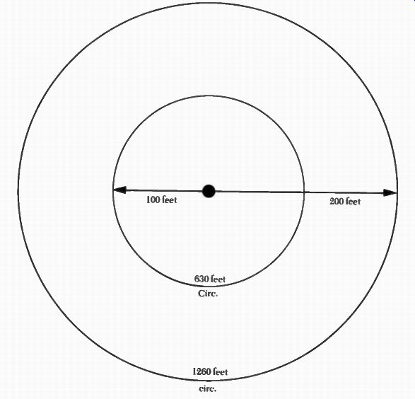
Figure 1-9. Illustration of how power from a radio station must spread
over increasing distances as it travels away from the radio tower.
Power. Power is an important factor in determining the size of the area in which a radio station can be heard. Once a radio wave leaves a station's tower no new power can be added. Thus, if the station has a power of 100 watts and if one measures all of the power at any distance from the station, it will not exceed 100 watts. At the antenna all of a station's power is concentrated in a very small area but as the radio wave moves away from the antenna, the station's power spreads over larger and larger circles of area just as a circle of water becomes larger and larger as it radiates from the point at which a rock enters the water.
Although the radio wave still contains most of the power it had when it left the radio antenna, the power is spread over larger and larger areas as the wave gets further and further from the antenna. For this reason, there will be less power available as one moves away from the antenna. See Figure 1-9.
For a receiver to pick up a station's signal, a minimum amount of power must reach the receiver from the station. This minimum will vary from receiver to receiver. Eventually, when one gets far enough from a station, the amount of power from the station that reaches the receiver's antenna will become so low that it is impossible to receive the signal. For the same reason the peaks on the water waves get smaller and smaller as the wave gets farther from the point at which it originated. The wave still has about the same amount of energy, but it is diffused over a larger area.
However, if a station were to increase its power, the amount of power at any distance from the antenna would be increased in direct relation to the increase in the station's power. Therefore, the distance at which a receiver could detect the station's signal would be increased. The higher power stations often reach an entire state or more, while the 250-watt stations rarely reach more than a small city and perhaps the surrounding county.
Clear Channels. Forty-five of the 107 AM channels have been designated as Class I clear channels. Some of the clear channels are used by stations in the United States, while others are used by Canada and other nations. In the United States, the FCC has authorized one or two high power stations to operate on each Class I channel. It should be noted that international treaties designate which countries have control over various clear channels--and, for that matter, all other radio and television channels.
The FCC intended that the high power stations would serve large cities. In addition, the stations were to broadcast to large rural areas that were unserved by other local or lower power stations. Most of the clear channel stations have a power of 50,000 watts, and none use less than 10,000 watts.
The FCC has designated secondary stations, which share a channel with the class I stations. This secondary category, class II stations, also serve large areas including major cities and often rural areas that are nearly as large as the primary station sharing the channel. When a "secondary" station shares a clear channel with a primary station, the secondary station's signal must not interfere with the primary station so that Class I stations can readily reach large areas. Like the class I stations, class II stations may have up to 50,000 watts of power, but they may have power as low as 250 watts. There are 29 channels designated as class II channels.
Regional Channels. Regional stations or, as the FCC calls them, class III stations serve a city and its neighboring rural area. The FCC has allocated 41 channels for use by class III stations. Several stations may occupy each of the class III channels, and stations with this classification may have a power ranging from 500 to 5,000 watts.
Figure 1-10. The complete AM radio circuit including the ground. Part of an AM wave flows through the air but an important part flows through the ground. The better the ground, the further an AM signal will reach.
Local or Class IV Channels. The FCC set aside six channels for purely local service. The FCC hoped that these stations would supply the needs for local news, sports, and entertainment. On each of these six channels there may be as many as 150 stations. These local stations may not have more than 1,000 watts during the day and 250 watts at night. 5 Location of Antenna. The location of an AM station's antenna can be more important to its coverage than its power. One half of an AM station's antenna is the type of tower you sometimes see dotting the landscape. The other half of the antenna is buried in the ground and is extremely important to the distance the station can cover. To cover the most distance many stations locate their antennas near water. Engineers have found that a 250 watt AM station with its ground wires buried in swampy soil sometimes has greater coverage than a 50,000 watt station with its ground wires buried in dry, sandy terrain. 6 A grounding system is important to an AM radio signal because, like all circuits, AM radio signals are "closed." As we noted before, closed means that electricity which starts at one point in a circuit can travel around the circuit and return to its point of origin. In the same way radio waves that leave the radio tower above the ground travel through space and then return to the under ground wires of the radio station to complete the circuit (see Figure 1-10). As with all circuits, the better the connection, the easier it is for electricity to flow.
Time of Day. AM stations can cover greater distances during the night hours than during daylight hours. This is because of the unique relationship of `ground," "sky," and "line of sight" radio waves. In Figure 1-11 we can see the relationship of each kind of wave. Ground waves tend to follow the curvature of the earth and, as such, bend around the earth. Line of sight waves are those waves that travel straight from the transmitter to your receiver. Therefore, as soon as you get out of sight of the transmitting station, line of sight waves no longer exist. Sky waves emanate from the transmitter towards the sky at an angle. Some distance above the earth these sky waves are reflected to earth by the ionosphere.
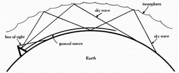
Figure 1 -11. Relationship of sky, ground, and line of sight waves.
During the day, AM stations depend largely upon line of sight and ground waves because the sky waves penetrate the ionosphere and are not reflected back to earth. Ground waves reach about the same distance during both light and dark hours and provide AM stations with a dependable coverage area. At night the ionosphere becomes more dense than it is during the day. Consequently, it reflects the sky waves back to earth so that people can receive AM stations at night that they would never be able to hear during the day.
Because radio signals cover greater distances at night, the FCC has decreed that some stations must turn off their transmitters at night. Other stations must reduce their power at night so that they will not interfere with the stations that remain on the air.
Noise. AM stations have a major problem that they have never been able to solve-noise. During lightening storms, an AM listener is often plagued by distracting loud pops and crackles. In fact some storms create so much noise that listening to an AM station becomes virtually impossible. This happens because lightening-or for that matter many other sources of electrical noise-can change the amplitude of an AM radio wave. The change in amplitude, of course, introduces undesirable noise onto the AM radio wave. The AM stations have found no solution to the problem of noise picked up from the atmosphere.
FM was to provide the answer.
Frequency Modulation. Frequency modulation (FM) broadcasting has the same goal as AM broadcasting-impressing sounds on a radio wave so that the sounds can be heard at great distances from the transmitter. But while AM stations vary the amplitude of the carrier in unison with the sounds to be transmit ted, FM varies the frequency of the radio wave. The FM radio wave wobbles up and down the radio spectrum in much the same way as water wobbles out of a hose when you shake it. The sound waves do not change the amplitude of the radio wave in any way when the radio wave is modulated.
Since FM radio does not depend upon the amplitude of the radio wave for modulation, atmospheric noises can not add noise to FM radio waves. Of course, these atmospheric noises do change the amplitude of the FM signal, but your FM radio does not detect the noises. The listener of FM, then, is not bothered by the usual AM static and crackle.
Size of an FM Channel. To make FM sounds particularly good and to afford opportunity to carry extra programs, the FCC created very wide FM channels.
Each channel has a 200 kHz band of frequencies. This is twenty times greater than a single AM channel of 10 kHz. This wide band of frequencies allows for high fidelity broadcasting. In fact, FM stations are required to keep their programming free from distracting noises. In addition, an FM station must be able to broadcast sounds up to 15,000 Hz, which is three times the range of an AM station.
Besides carrying high fidelity programs, FM can also carry second and third channels of programming on its radio wave. For example, many FM stations now broadcast stereophonic programs. Some FM stations also carry a separate music program-for public broadcasting in stores, for example. The commercial music cannot be picked up by your home set without special equipment. Broadcasting background music has saved many FM stations from financial ruin, because the music is sold to stores who wish to subscribe. (See Figure 1-12.)
FM Broadcast Band. The band of frequencies allocated to FM broadcasters extends from 88 to 108 mHz. This allows for 100 different FM channels. The first twenty channels were specifically set aside for educational users while the other 80 channels were open to anyone who wished to use the channels. FM stations do not generally cover areas as large as the larger AM stations so the FCC was free to place many FM stations on each of the 100 channels. To guide in the placement of FM stations, the FCC drew up a table indicating geographic areas where applicants might build a station.
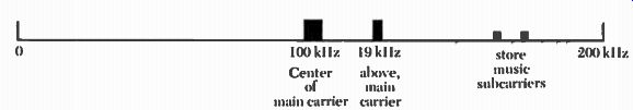
Figure 1-12. Diagram of an FM channel. An FM channel as authorized by
the FCC is 200 kHz wide.
When the FM carrier is being modulated at full volume (100%) the FM carrier shifts 75 kHz above and below the center frequency. An FM station that programs in stereo has a 19 kHz carrier modulated on to the main carrier. This stereo subcarrier (as it is called) is separated from the main carrier by the equivalent of about two AM channels. In addition, a FM station may add up to two additional subcarriers for carrying music for stores. These subcarriers are more than 60 kHz above the main carrier frequency. This is the equivalent of more than six AM channels. These subcarriers are modulated by AM and the design of FM receivers prevents picking up all subcarriers at once.
Factors Affecting the Coverage of FM Stations
Unlike AM broadcasting, FM signals cannot travel far beyond the horizon.
Thus there are no "clear channel- stations in the FM broadcast band. The two factors that govern the coverage of an FM station are the height and type of the antenna and the power of the transmitter.
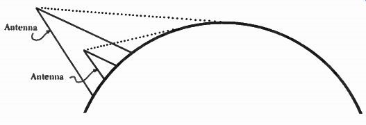
Figure 1-13. Effect of two different antenna heights on FM coverage.
Antenna Height. More than any other factor, antenna height dictates an FM station's coverage. The very high frequencies (VHF) assigned to FM perform much like light in that they travel in a straight line with FM ground and sky waves of little importance. FM sky waves are not reflected back to earth as are AM waves so they are of no consequence to the listener of a FM station. FM ground waves are also insignificant since they are unable to bend around the earth as are AM waves. For these reasons FM stations are totally dependent upon the waves that travel straight from the FM station to the listener's receiver.
The higher a FM station's antenna is above the average ground level the greater these line of sight waves will travel before the curvature of the earth cuts off reception. Notice in Figure 1-13 how raising the antenna to a greater height causes the waves to reach farther around the curve of the earth. As with AM stations, there are classifications for FM stations and these classifications dictate the height of an FM antenna. Class A stations may erect an antenna that is 300 feet above the average elevation of the land around the station. Class B stations may go to 500 feet and class C stations to 2,000 feet. 8 Power. Although FM broadcasting is limited to line of sight reception, the power of a station can improve reception in distant areas. The FCC has adopted maximum power limitations for stations in each of the above three classes: class A-3,000 watts; class B-50,000 watts; and class C-100,000 watts. Therefore the FCC authorizes the combination of high power and tall antenna to some stations and low power and short antenna to other stations.
CONSEQUENCES OF ENGINEERING DECISIONS
The FCC seldom makes an engineering decision on technical considerations alone. When the FCC decided on the location of the AM or FM bands, it did so after considering the conflicting demands of several groups of people and companies. The FCC must consider the economic consequences of different decisions and it must evaluate the effects of a decision on the long range development of radio. When the FCC-and before it the FRC--considers a new engineering rule or regulation, companies with an interest in the decision rally their forces to influence the FCC to rule in their favor. This kind of situation arose first when the FRC considered what to do with AM stations. Later, when the FCC contemplated FM channels, the same types of forces came to bear on the FCC. In both cases the parties with the greatest influence appeared to win.
When the FRC was allocating AM frequencies to different station operators, commercial broadcasters wanted all of the channels. Although there were more than 171 educational AM stations before 1925, only about two dozen are still on the air. 9 Educational institutions did not have sufficient assets to operate their stations and when commercial broadcasters agreed to provide free air time to educational users, most educational stations were sold to commercial operators.
The FRC exhibited no interest in maintaining certain channels for educational use and willingly accepted the solution suggested by commercial radio.
Although commercial stations had promised extensive educational programs, very few stations carried out their promise.
Of more severe consequence was the decision to create class I, H, III, and IV stations. The clear channel stations, which are usually located in large markets, have been able to make large amounts of money while many of the class IV stations have had great difficulty in breaking even. Indeed the FCC's classification virtually guaranteed that some stations would become rich while other suffered. The favored status of the class I stations is so great that they have formed an association to protect their position. This clear channel association spends much of its time lobbying before the FCC in the interests of the clear channel stations.
The history of the FCC's handling of FM radio is fraught with what appears now to be some misjudgments. The development of FM came just as large corporations like RCA were trying to exploit the commercial possibilities of television. Consequently, RCA wished to stall the development of FM while it contemplated television. Both FM and television were unable to develop during World War II. Then in 1945, as the war was ending, development of television and FM became an issue again.
Prior to 1945, FM had held the frequencies between 43 and 50 mHz." In 1945 the FCC adopted a rule which ordered the change in FM frequencies to the present 88 to 108 mHz. The FCC declared that its decision was based on a long-range concern for the development of FM. A military engineer who testified before the FCC argued that sunspots might damage performance of FM broadcasting in the 43 to 50 mHz frequencies. Although the engineer's data was classified by the military and thus not open to examination, a group of companies including RCA, Philco, Crosley, and Motorola agreed with the engineer in asking the FCC to change the FM band to higher frequencies.
These companies were committed to speedy development of television and thought the lower frequencies would be particularly good for television broadcasting. FM, they thought, should use the higher and less desirable frequencies. The television group thought that the lower frequencies would permit television stations to have greater reach than they would have at higher frequencies.
Moving FM to another channel space damaged its development because it had already become established in its 43 to 50 mHz band with some 47 stations on the air and 500,000 receivers in operation. Moving to new frequencies required the construction of new transmitters and receivers-an expense neither the stations nor the public was willing to incur. Indeed proponents of FM had argued vigorously against the move to higher frequencies, but their arguments went unheard.
The development of FM was effectively stopped until the 1960s by the decision to move FM to higher frequencies. The FCC's own 1949 annual report indicates a leveling off of FM applications and a great increase in television applications. Those with the funds to fight the FCC--in this case the television interests led by RCA-won a substantial victory at the expense of FM." However, the FCC did decide to allocate twenty channels between 88 and 108 mHz for education, which was fifteen more than had been available in the lower FM frequencies. Even this partial success was largely ineffective because educators did not have the money to buy new transmitters.
TELEVISION
While radio provides only sounds, television adds a picture to those sounds. Al though experimenters were trying to develop television before 1900, it did not reach the public until the late 1930s and the early 1940s.
Since television has two channels of information, picture and sound, a tele vision station must duplicate all equipment except the transmitting antenna.
There are two transmitters in the station and usually two control rooms. The station generally employs an individual to control the flow of sounds to the transmitter and another person to control the pictures that are broadcast.
The television picture is impressed upon a radio wave by amplitude modulation while the sound is frequency modulated on another radio wave.
The process of modulating the sounds, therefore, duplicates the methods discussed under frequency modulation radio. Although the picture uses amplitude modulation, the process of placing a picture on a radio wave is more complex than the process of modulating sounds. We shall examine how television pictures are created and how they reach the radio wave. But first we must discuss some aspects of pictures that affect how television images are created.
Picture Quality
Newspaper pictures, television images, even photographs are comprised of thousands and thousands of microscopic dots of color. To our eyes these dots appear continuous, but if we had microscopes or even good magnifying glasses, we would quickly find that the pictures result from a composite of small dots.
No one has yet discovered a method to create a perfectly continuous picture, so pictures are made up of rows and rows of small dots. Since our eyes cannot perceive the many small dots, we see the picture as a continuous whole. But when the dots of the picture become too big, our eyes have difficulty discerning a picture.
The term resolution refers to the picture quality associated with the number of dots used to construct the picture. As the number of dots in the picture increases, the resolution of the picture improves. On the other hand, as the number of dots decreases, the picture becomes unsatisfactory.
A television picture contains about 367,000 dots. 12 These dots are divided into neat rows that run horizontally across the face of the television screen. In fact there are 525 rows of dots in an American television picture. The FCC decided that this number of dots and rows was the best compromise between good resolution and the limits on the amount of channel space that could be allocated to television broadcasting. Each horizontal row of dots in a television picture is often called a line. Thus there are 525 lines of dots on a television picture tube face. This sometimes gives rise to the term "line system" in referring to the system of television scanning. Not all television systems employ 525 lines. In fact, most European nations use a different number of lines such as 625. Therefore, in this section when we refer to 525 lines of resolution we are referring to the American system of television.
Television and the Illusion of Motion
Although we see television and motion pictures as moving images, in reality they are a series of stills projected rapidly upon a screen. If you examine a piece of motion picture, you find that it is composed of many still photographs placed in a row on the film. Each photograph is called a frame. When the film is projected, we see not a series of still frames, but a continuous moving image.
Although the image of many still pictures reaches our eyes, we are unable to see single frames and because of the phenomenon of persistence of vision, we subconsciously blend the slight jerks together and perceive a continuous and moving image.
Persistence of Vision
We have discussed the fact that the eye tends to blend still photographs, but we still have the problem that the screen has no picture about half of the time while a new frame is moving into place. The projector contains a shutter that interrupts the light while a new frame is pulled into position, leaving the screen dark during this time. Each picture frame remains motionless while it is being projected-the time when the shutter is open.
We do not perceive the screen as being dark because of persistence of vision. Perhaps you have been in a dimly lit room when someone photographed you using a flash attachment. You may remember that the image of that flash was 'burned' into your eye for several seconds after the picture was taken. This capacity to retain images on the eye is called persistence of vision and is essential to our viewing of film and television.
Just as you saw the flash for a short time, so you see the projection of a film frame for an instant after it has vanished. This slight delay on the part of the eye can cause the viewer to think that there is always a picture on the screen.
Without persistence of vision, television would appear. Without persistence of vision, television would appear to be a long series of disjointed still photographs and it would be impossible for us to enjoy motion pictures or television as they now exist.
Experimenters have found that for the human eye to perceive the projection of a picture as continuous motion about eighteen frames of pictures must be projected each second. However, if only eighteen flashes of light, fall upon the screen, the eye will see a flickering picture. To reduce the flickering each frame of film is projected twice. In television where there are thirty frames projected each second, each frame is scanned twice. In one scanning only the odd lines such as one, three, and five are scanned while in the second scanning only the even lines are scanned.
Mechanics of Television Picture
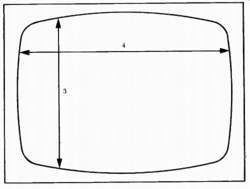
Figure 1-14. Dimensions of a television screen.
Aspect Ratio. Television pictures are always projected in a horizontal shape which is about four units wide and three units high as is shown in Figure 1-14. This shape conforms to the original shape of motion picture screens and has long been accepted as the most comfortable for the eye to view.
Image Size. While the rectangular shape of the television picture has been fixed, the dimensions of the border have not. Early sets were very small, with diagonal measures of only six to nine inches. Modern sets have diagonal measures ranging up to 25 inches, and projection television sets may project images up to six or eight feet across. No matter how large or how small the size of a picture, all television pictures contain the same amount of resolution or picture information. There is no way that one can project more than 525 lines of dots onto an American television screen. Thus, large screens will not give better pictures than small screens.
How a Television Camera Works
The television camera is the device that picks up the television picture and converts the picture into electrical signals so that it can be imposed on a radio wave by means of amplitude modulation. The important element in the tele vision camera is a pickup tube that receives light focused upon it through a lens and converts the light into an electrical image. Within the camera tube is a light sensitive plate akin to light sensitive film in a film camera. This plate is composed of about 367,000 small light sensitive dots deposited in orderly rows on the plate. These dots release electrons-electrons are negatively charged particles--when light falls on them. Each dot releases a quantity of electrons corresponding to the amount of light falling on it. A bright spot would release more electrons than a dark spot.
The electrons released from the light sensitive plate travel a short distance to another small glass plate called the target. Like the original light sensitive plate, the target has some 367,000 dots and the electrical charge that reached the target from the light sensitive plate creates a corresponding--but larger-- charge. Thus, on our second plate we have an electrical equivalent of the picture appearing on the original light sensitive plate. Our problem is to lift this image from the target and send it on to the transmitter.
---------------------
THE SEVEN FOOT TELEVISION
At least one manufacturer, Advent, is producing a television set that will project a seven foot (diagonal) picture upon a wall screen. The set throws a beam from a control unit eight feet to a screen mounted on a wall. Although the cost is well above that of conventional sets, its manufacturer predicts that large screen television will shortly start coming down in price. The unit, its maker says, requires no more power than a conventional set.
Source: "Wall-Size TV: The Ultimate Idiot Box," by Andrew Tobias, New York (August 4, 1975), p. 32.
-------------------------
An electron beam is projected from the back of the pickup tube towards the target. This beam wiggles back and forth, up and down so that it can scan (or impinge upon) each of those 367,000 dots. As the beam scans each of the thou sands of dots, it picks up the free electrons and carries them back to the rear of the pickup tube. The magnitude of the beam is varied in relationship to the intensity of light falling upon the original plate. When it reaches the bottom of the picture, the scanning beam moves back to the top of the picture and starts the process again. This scanning (sometimes called scansion) of the target is set up in such a way that each dot is scanned thirty times every second and is synchronized with a similar beam of electrons in the television set in your home.
This individual scanning of each dot occurs because a television channel is unable to transmit the output from all of the dots at one time, therefore, each dot must be read in its turn. In this way each dot in your television is illuminated in its turn. In addition to the picture information, synchronizing and blanking impulses are sent. Let's use a typewriter to illustrate the need for synchronizing and blanking impulses. Suppose two automatic teletypewriters are connected, one generating information and the other typing the information out. You know that it is necessary for the sending and receiving ends to keep in step so that when the end of a line comes at the sending end, it will be matched by the end of a line at the receiving end. In addition it is necessary to cause the carriage to move from left to right and from top to bottom. The same thing is necessary in television, and it is the role of the synchronizing and blanking impulses to control how each of the dots is scanned.
Just as the pickup tube in the television camera has a mosaic (light sensitive plate) and an electron gun, your television picture tube has its own electron gun and something related to the mosaic. Behind the face of a picture tube there are many thousands of dots of phosphorus material-one dot to match each dot on the mosaic in the pick-up tube. These phosphorus dots can be illuminated by electrons-the more electrons hitting the phosphorus material, the brighter the light.
Let's suppose all we are going to see is a picture of a large, black X against white background. The electron beam in the camera will sweep across the mosaic from left to right and top to bottom. While tracing the white area the camera will have a high output, but when it hits the dark X the output will go down.
Now let's consider what happens at the television receiver. When the electron beam is scanning the part of the television screen that corresponds with the white area, many electrons will be hitting the phosphorus dots and they will glow brightly. However, almost no electrons will reach the screen when the electron beam is scanning the area where the X appears. The television set has shown an image of a black X on a white background.
Of course, if the electron beam in the camera doesn't scan its mosaic in just the same way the electron beam in your television set is scanning the screen, then the picture begins to roll or straight lines become curved. When this hap pens, a readjustment of the set is called for.
Scanning Patterns. One complete scanning of the mosaic plate in a pickup tube is called a frame, and it compares to a single picture or frame of a motion picture. Just as the motion picture frame is really a still photograph, so a single frame of television is only a still picture. The assembling of many still television pictures into a sequence gives the illusion of motion in the same way that the illusion is created by motion picture frames.
The electron beam scans the mosaic thirty times every second, which means that television broadcasts thirty frames per second. But your television set and the camera are so constructed that the electron beam scans only every other line. Thus lines one, three, five, and so on are scanned first. Then when the electron beam has reached the bottom of the picture it returns and scans the lines that were missed the first time. On the second scanning the electron beam covers lines two, four, six, and so on. Although the electron gun scans the entire picture only thirty times per second, it appears that the number of scannings have been doubled to sixty. This apparent scanning frequency of sixty corresponds to the frequency of ordinary house current, which has a frequency of 60 Hz. Engineers found it desirable to relate the number of frames per second to the frequency of house current because they found that when the television frame frequency was different from that of house current the picture would flicker and make television viewing impossible. (See Figure 1-15.)
Camera Pickup Tubes. Valdimir Zworykin invented the earliest television pickup tube and called it the kinescope (see Figure 1-16). Newer, more sensitive tubes and cameras have since replaced the kinescope. More sophisticated ...
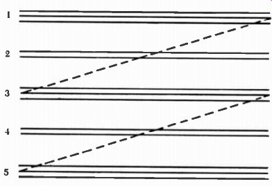
Figure 1-15. Diagram of scanning pattern used in American television.
On first scan the odd-numbered lines are eliminated by the electron beam.
On a second pass, the even rows are eliminated. This gives the illusion
of two frames for each complete scanning.
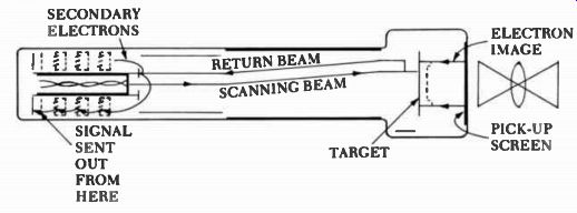
Figure 1-16. Diagram of a television pickup tube.
... cameras include the image orthicon camera, the plumbicon camera, and the vidicon camera.
The image orthicon camera which was invented before the vidicon or the plumbicon is the standard television camera in most broadcast operations for two reasons. First, because it requires less light than other cameras, it can be used in very low light situations. The image orthicon derives its sensitivity be cause as electrons travel from the light sensitive plate to the target, the electrons gain so much speed that they dislodge many electrons in the target, making the tube particularly sensitive. The second advantage of the image orthicon is its excellent picture detail. The small dots of the light sensitive plate and the target tend not to release their electrons to adjacent dots. By keeping the electrons from jumping from dot to dot, smearing of the image is reduced and the picture quality is enhanced. The major drawbacks of the image orthicon camera are its cost and its sensitivity to physical vibration.
More recent was the invention of the vidicon camera which is smaller, cheaper, and less fragile. The combination of low cost and ruggedness made the vidicon camera immediately popular for educational use and for people with limited funds. But the vidicon suffers from inferior picture quality and it lacks the low light sensitivity of the image orthicon camera.
The plumbicon camera improved the vidicon in that it was able to respond to low light situations like the image orthicon while having the ruggedness of the vidicon. The plumbicon camera receives extensive use in portable or mo bile applications. Today, these three tubes are the only ones used in educational and broadcast television.
Channels for Television Broadcasting
Like radio, television broadcasting requires a band of frequencies to accommodate all of the information that must be transmitted, but the band of frequencies needed to contain all of the picture and sound information must be quite large. If a high quality picture is to be transmitted, then a wide band of frequencies must be allocated for each television channel. In addition, the quantity of radio frequencies needed for television broadcasting would increase ...
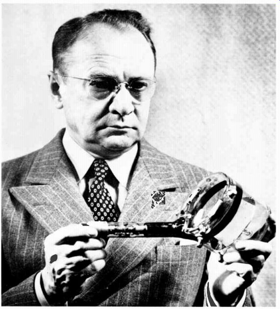
Vladimir Zworykin is holding a kinescope tube he used for picking up
pictures and converting them into electrical images. As you can see,
the tube is quite large, but it made possible the kind of television
we enjoy today. (Culver Pictures.)
... as the number of channels increased. Consequently, the FCC was confronted with the complex tasks of providing an adequate number of channels large enough to transmit pictures with good resolution as well as providing for the needs of radio users. When the FCC first confronted the problem of television channels, the technology for using UHF (ultra high frequencies) had not been fully developed. The FCC was limited to using VHF (very high frequencies) for any television allocations.
From its hearings the FCC decided to allocate thirteen (later reduced to twelve) channels for commercial television broadcasting. This decision rested upon the belief that thirteen channels would satisfy the current needs of television broadcasters. Later, when UHF developed, the FCC expanded the existing channels to include sufficient UHF channels to satisfy any additional demand.
In deciding on the size of a television channel, the FCC settled on a six million Hertz band of frequencies for each television channel. This choice made it possible to broadcast most of the 367,000 dots of picture information that a television camera produces along with the synchronizing, blanking, and sound information.
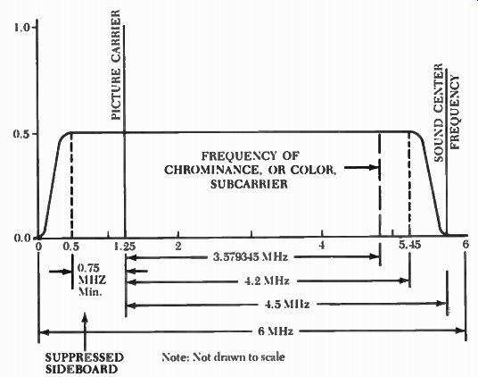
Figure 1-17. Idealized picture transmission amplitude characteristic.
Source: FCC § 73,699, Figure 5.
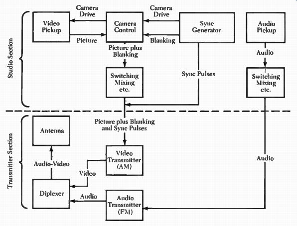
Figure 1-18.
The use of a television channel is shown graphically in Figure 1-17. The bottom frequency of a television channel is designated by zero and the top by six megaHertz. Note that the carrier frequency for the picture is located 1.25 mHz above the bottom of the channel and the radio wave, which carries the sound, is located .25 mHz below the top of the channel. These are the locations of the two carriers when no picture or sound is being transmitted.
When modulation occurs most of the six million Hertz must carry sound and picture information. As the amount of information that must be carried on a radio wave increases, the number of frequencies used must be correspondingly increased. To conserve channel space all of the picture information that is modulated below the radio wave or carrier is suppressed before the television picture is broadcast. Since the information modulated on each side of the radio carrier is identical, no picture information is lost. Of course the process of eliminating some information is not perfect, so the FCC left some frequencies between the radio carrier and the bottom of the channel for the remnants of the suppressed waves. A total of 1.25 mHz was set aside for this purpose. Thus the actual picture information uses the frequencies from 1.25 mHz to 5.25 mHz. As you can see, a great many frequencies must be used to transmit a television picture.
Transmitting a Television Program
As we noted earlier, there is separate equipment for sound and picture in both studio and transmitter equipment at a television station. Figure 1-18 shows typical television station equipment. In the audio or sound portion of the station there are microphones, tape recorders, and turntables to provide sources for sound. All of these components come together in a control board that permits the appropriate sources to pass to the transmitter. From the control board the sounds travel to a FM transmitter where they are modulated onto a radio wave.
The picture portion of the television station is more complex. First, there are lights, television cameras, video tape recorders and film projectors, and slide projectors providing pictures-the video tape recorders and film projectors also provide sound to the audio control board. Obviously, if all of these picture sources were permitted to travel to the transmitter without any control, we would have a jumbled mess of pictures. For this reason a control board, often called a switcher, selects the sources to be transmitted. This switcher may make rapid cuts from one picture source to another, it may fade out of one camera and into another, it may dissolve from picture to picture, or it may create a vast number of complex special effects. The results of the switcher are sent to the visual transmitter.
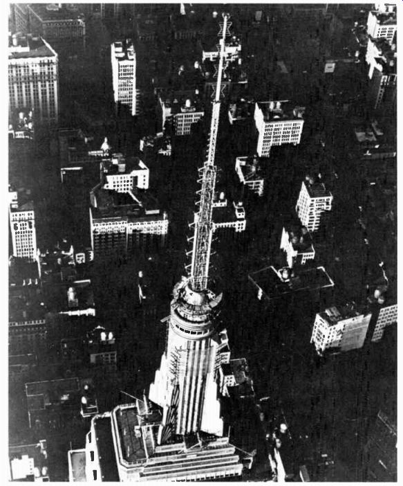
------- An antenna used by television stations in New York City
to send television pictures through the air.
This antenna is located on the Empire State Building. ( Courtesy Empire State Building.)
Color Television
As yet little is known about how people see color, but enough has been discovered to make it possible to transmit color pictures via television. Although there are many colors, it is necessary to transmit only the three primary colors to see a full color image. These primary colors are red, blue, and green. With this in mind, color television is really three complete television systems-one for each of the primary colors.
In the color television camera there are actually three pickup tubes. As light enters the camera it is split up according to its color. Some is sent to a green tube, some to the red tube, and some to the blue tube. These three color signals have two important qualities-hue (color) and brightness (intensity). It is necessary to combine all of this picture information on a radio wave just as we once combined black and white colors on a radio wave.
The brightness part of the color signals are modulated onto the radio wave in much the same way as brightness is modulated in black and white television.
Thus there are three brightness components combined on the radio wave.
The hue or color information is modulated onto a separate radio wave that is attached to the main radio wave. This separate radio wave is called a subcarrier and acts in a way that is similar to the way FM stations broadcast a stereophonic program. At the receiver, all of this information is disassembled and used to control three color electron beams that scan the face of the picture tube.
Unlike black and white television sets, which have many phosphor dots that become white when hit by the electron beam, the color receiver has many dots that become red, blue, or green when hit by electrons. For every single dot in a black and white set, there are three dots in a color set. One might expect to see three separate colors because of the three dots, but this is not the case. Our minds like things to fit together neatly, and because of the small size of the dots, the brain merges the three dots into a single dot the color of the combined the light which escapes from the three individual dots.
When a black and white picture is being transmitted and a color set is receiving the picture, the same color dots produce a picture that your eye perceives as a black and white image. The design of the present system of color television is compatible with existing black and white television sets and transmitters so that no television sets became obsolete with the advent of color television.
ENGINEERING DECISIONS, ECONOMICS, AND TELEVISION
As mentioned earlier, the FCC allocated thirteen VHF channels for television broadcasting in 1945 hoping that these would satisfy the demand for television channels. The FCC knew that it would be unable to allocate any more VHF frequencies for television broadcasting because it had to accommodate the demands of FM broadcasters, radio amateurs, and many others who wanted part of the VHF spectrum-the FCC later reduced the original thirteen channels to twelve. In 1945 the FCC believed that if there ever was additional demand for television channels, the channels could be placed in the UHF region of the radio spectrum. In 1952 the FCC decided that it had not allocated enough channels for tele vision broadcasting and so introduced UHF television by establishing channels 14 and above. These UHF channels were added both to markets that already had VHF television channels and to markets that had no television channels at all. But UHF television has two major disadvantages. First, UHF signals do not travel as far as VHF signals; second, most television sets do not have the capacity to receive UHF television stations. Consequently, UHF television faced crippling competition from its VHF counterparts. In fact the competition was so great that many UHF television stations were forced out of business. The FCC engineering decision permitted an economic environment that virtually guaranteed a monopoly for VHF television stations.
Not until 1962, when the United States Congress passed a law requiring all television set manufacturers to include tuners that could pick up UHF television stations on all new television sets, did UHF have a chance. Although UHF now makes some profit, the large VHF stations still dominate television broadcasting.
A similar conflict arose when the FCC considered color television. Several companies had plans for color television systems including Columbia Broadcasting System (CBS) and Radio Corporation of America (RCA). During the late 1940s and early 1950s, when the FCC considered color television, the RCA system was more developed than the CBS system. Also, it should be noted that the RCA system was compatible with the existing black and white television system while the CBS system was not. The FCC approved the RCA color system in 1953 and rejected others. At the time, the question was raised whether the CBS system might produce better color pictures than the RCA system. Whatever the case, RCA and the National Television System Committee--an industrial group formed to promote television development--urged the FCC to adopt the RCA system. When the FCC accepted the RCA color system, it gave RCA a monopoly on color television patents and required CBS and ABC to purchase the rights to use the patents from RCA. This gave RCA a very desirable market position for years. In fact RCA and its network, NBC, were the earliest broadcasters of extensive color television programs.
Many years later, the United States government used the CBS color system to broadcast color pictures from the moon. Presumably, they selected the CBS system because it was superior to the RCA system.
NETWORK RELAY SYSTEMS
Almost from the beginning of radio, broadcasters realized that they needed some way to unite various stations for simultaneous airing of programs. They found that producing their own programs was too expensive for the amount of advertising revenue that individual stations could acquire. They concluded that a central source of programs would benefit a number of stations at once.
Wire Relays
Early broadcasters experimented with connecting stations by wires owned by American Telephone and Telegraph Company (AT&T) since they were readily available. In fact years before broadcasting began, AT&T had connected much of the nation by telephone wires. These wires provided the basis for the first radio interconnections. Also, Western Union provided wires for early radio connections. Although broadcasters found that these wire connections were particularly successful, they felt that sounds were not reproduced with sufficient clarity. AT&T, along with new network companies, began experimenting with different systems of interconnection.
Coaxial Cable
An invention that made possible the transmission of both high fidelity sounds and television pictures was the coaxial cable. As can be seen in Figure 1-19, coaxial is in reality a wire within a wire. The inner wire is suspended by an insulator inside a cylindrical wire shield. Although the coaxial cable requires considerable service, it is used to connect television and radio stations into net works. Coaxial cable is the basis of cable television systems, and network hookups.
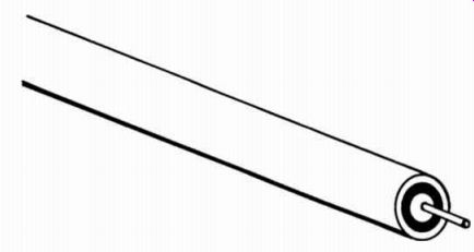
------ Figure 1-19. Diagram of coaxial cable. The outer surface
is an insulating material which protects a cylindrical metal shield just
under the insulator. Separating the metal shield and the inner wire is
another insulator. Thus, a coaxial cable is really a wire that completely
surrounds another wire.
Microwave Relays
By using transmitters tuned to radio frequencies well above the television broadcast bands, engineers found that they could relay television pictures for ...
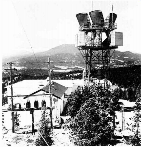
-------- This microwave tower can send pictures, computer
data, and telephone calls through the air in a very specific direction.
This made possible coast-to-coast network television. (Western Electric.)
... distances of at least thirty miles. Microwaves, as these high frequencies are usually called, may be focused in the same way as light from a high power flashlight. This focusing allows for the transmission of radio and television signals from one microwave tower to another across the United States. Like light, microwaves travel in straight lines and cannot bend around the surface of the earth.
AT&T found that by using a combination of microwave transmission and coaxial cable, it could create a link for television that crossed the United States.
Their first transcontinental hookup, which had the ability to carry television pictures, was finished in 1951. But microwave connections could not span oceans, nor could they be used effectively in mountainous areas.
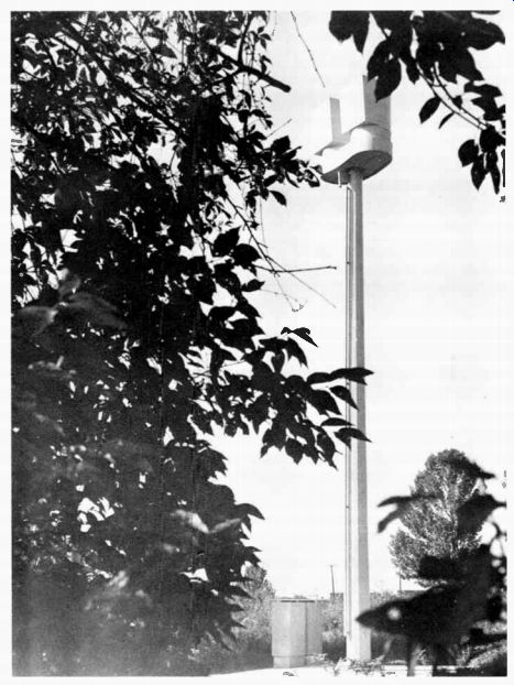
--- This is a more modern version of a microwave tower and
antenna capable of transmitting many signals. ( Bell Laboratories.) Although
microwaves do not bend around the surface of the earth, they are scattered
by the ionosphere and other elements in the atmosphere. This means that,
through scattering, a small amount of the microwave energy returns to
earth many miles beyond the usual thirty mile limit. In 1955 the Canadians
began experimenting with picking up these scattered waves. Their successful
experiments led the United States to similar experiments in 1957.
Using very sophisticated equipment it was discovered that microwave links
could be used over 600 mile distances.
Satellite Links
Most of the earlier links required ground equipment in the forms of coaxial cables, amplifiers, or microwave stations every thirty miles or less. Satellites solved most of these problems by making possible transmissions over great distances without the need for frequent ground stations. In fact one satellite permits coverage of fully one-third of the earth's surface.
The earliest satellites did not have transmitters or receivers, but were merely reflectors that worked as giant mirrors in the sky. These satellites, which were made of metal coatings on large plastic balloons, were of limited value. Later experiments led to satellites which had their own transmitters and receivers. These satellites received a signal from earth and retransmitted the same signal back to earth. Some of the more sophisticated satellites can handle several television pictures in addition to hundreds of telephone conversations.
Satellites hold the greatest promise for inexpensive interconnection for net works. In fact Home Box Office (HBO), which is a company supplying movies to subscribers in return for a fee, already uses satellites to connect some of its systems. As satellite systems develop further, more and more network pro grams will undoubtedly be sent to stations and cable systems by satellite.
DISTRIBUTION SYSTEMS
Cable Television Cable systems are able to distribute a much greater variety of programs than radio and television stations. Radio and television stations are limited to the number of channels that the FCC has authorized to each of many different services that wish to use the radio spectrum. In the case of cable systems, usually the programs are carried to homes by a wire and do not travel through the air. Consequently, the cable programs do not compete for limited radio frequencies. Cable operators may put as much or as little on the cable system as they desire without competing with any other radio or television use.
--------------
THE ULTIMATE VIDEO FREAK
The choices to the video freak are rapidly becoming endless.
Besides a moderate selection of through-the-air television channels, there are a variety of special services. Some cable stations now offer well over twenty channels. Often the same program can be seen on two or more channels.
If the cable system basic service isn't enough, many systems now offer Home Box Office or another pay television channel. These channels provide commercial movies and sports. There are video tape recorders, video disc machines, small televisions, and wall televisions. And you may purchase your own television camera to produce your own video when all else becomes boring.
-----------------------
Cable was originally envisioned as an auxiliary service to broadcasting, and cable systems were constructed in areas not served by television stations.
When people discovered that cable could bring more channels than could broadcasters, cable began extending into markets already served by television stations. Besides offering more programs, cable can bring clearer pictures to more homes than can be received out of the air. In New York, for example, skyscrapers obstruct the travel of television waves, but cable systems are not affected by the buildings. Subscribers thus receive much clearer pictures than do those with regular antennas.
Translators
Television stations sometimes use translators to send their signals into areas blocked off by mountains. These translators are low power transmitters that receive a signal from the main transmitter and rebroadcast it into those areas not reached by the main signal. Mountains cast shadows which prevent television pictures from reaching into valley areas. The low power transmitters operate on a frequency other than the frequency used by the main transmitter so that the two transmitters do not interfere with each other. On occasion, translators have been used to carry the signal of a television station beyond the reach of the primary transmitter.
Short Waves
Originally explored as a method for interconnecting radio broadcasting stations, short waves have proven most effective in broadcasting programs across international boundaries. The United States, and almost every other nation of the world, uses short wave broadcasting to send and receive information and propaganda. The use of short wave broadcasting is outside the scope of most commercial broadcasters in this country and, therefore, is of little concern to them.
NOTES
1. Richard Brown, Media Technology (New York: Broadcast Institute Of North America, 1974), P. 28.
2. Frederick E. Terman, Electronic and Radio Engineering (New York: McGraw Hill, 1955), p. 8.
3. Walter B. Emery, Broadcasting and Government: Responsibilities and Regulations (East Lansing: Michigan State University Press, 1971), P. 30.
4. FCC, "What You Should Know About the FCC" (Washington, D.C.: FCC, 1973), pp. 41, 42.
5. Ibid., p. 22.
6. Terman, op. cit., P. 923.
7. FCC, op. cit., P. 26.
8. Ibid.
9. Ibid., p. 23.
10. Erwin G. Krasnow and Lawrence D. Longley, The Politics of Broadcast Regulation (New York: St. Martin's Press, 1973), pp. 86-91.
11. Ibid.
12. FCC, op. cit., P. 29
13. This section is based upon a written but unpublished explanation by Glen Bishop.
14. FCC, op. cit., p. 33.
15. Krasnow and Longley, op. cit., P. 96.
16. FCC, op. cit., P. 34.
17. Keith Henny, ed., Radio Engineering Handbook, 5th ed., (New York: McGraw Hill, 1959), P. 18-1.
Also see: DIY low-power transmitter projects ; Radio Communications Receivers -- A guide to radio receiver design and technology
FM by Transmission and Reception (1954)