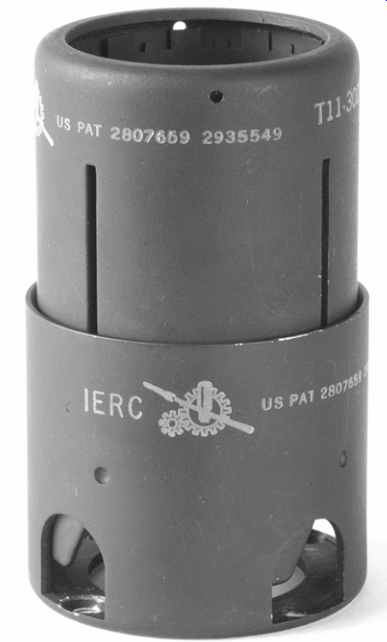
From left to right
The first ''screening can'' was actually manufactured as a heat sink, and slightly reduces envelope temperature. All that is needed to turn it into a screen is a short wire to bond it electrically to the chassis. The dungaree screening can is a bayonet fitting onto a skirted base and has holes to allow air to flow, which reduces its screening efficiency and temperature rise. Note that the inside of the can is painted matt black to absorb radiant heat from the valve, which is then reradiated by the black outside surface. The third can is for small-signal tubes only as airflow is very restricted, but the black paint inside and outside assists cooling. The fourth can is an abomination and deserves to be crushed because not only does it restrict airflow, but it insulates the radiant heat from the valve.
Very occasionally, screening cans are deliberately made to aid heat losses, and have fingers to contact the glass envelope (see FIG. 17).
Input sockets
Input sockets should be kept apart from mains wiring (hum) and loudspeaker terminals (instability), but as both of these problems are caused by capacitance from the input socket to the offending connectors, screening the input socket cures the problem easily if space is limited.
An extremely useful facility on a power amplifier is to add a muting switch that applies a short circuit to the input of the power amplifier (see FIG. 18).
Not only does the muting switch enable the amplifier to be plugged to different sources without having to switch it off and then on again, but it is very handy when the amplifier is being tested. The 1 kOhm resistor protects the output of pre-amplifiers, etc. from the short circuit.
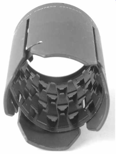
FIG. 17 Screening can with internal fingers to aid heat dissipation
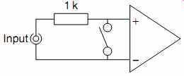
FIG. 18 This muting switch at the input of the amplifier enables audio
leads to be swapped without the necessity of switching the amplifier off
Mechanical/safety
The purpose of the chassis is to support the components mechanically, some of which are heavy, and to enclose all the dangerous voltages, thus eliminating the risk of electric shock.
The safest form of chassis for the home constructor is the totally enclosed grounded metal chassis. Placing a mains transformer in the center of a chassis made of folded aluminum is asking for the chassis to sag. Heavy items should be placed towards the edges, where the nearby vertical section adds substantial bracing.
If a heavy item must be moved towards the center of a chassis, a bulkhead or two can be added across the chassis to brace it, giving the further advantage of breaking the inside of the chassis into electrostatically screened compartments. This allows noisy circuitry (rectifiers and smoothing) to be placed in a ''noisy'' compartment, and sensitive audio in a ''quiet'' compartment (see FIG. 19).
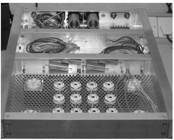
FIG. 19 Chassis bulkheads allow segmentation into ''dirty'' or ''clean''
compartments
When planning the positions of the major parts, it is important that one part should not obscure electrical connections or securing screws of another unless it can be easily moved aside to gain access. Think carefully about accessibility of screws and nuts.
It's time to reconsider if you can't easily fit a spanner or nut driver onto a nut, or a screwdriver into a screw head. If there's really no choice about nuts being inaccessible, consider securing the part with a single 3mm plate having tapped holes in lieu of individual nuts. Failure to observe these considerations can make subsequent maintenance extremely difficult. Typical consumer electronic design places maintainability very low on its list of priorities, but not only do you want to be able to maintain your creations, you also want to be able modify them as your knowledge expands or when better parts become available.
It is often useful to take a modular approach. If a block such as a complete heater supply including mains transformer, rectification/smoothing and regulation is made as a module on a sub chassis, it can be conveniently built and tested outside the main chassis, then installed when ready. A printed circuit board (PCB) is another example of this technique.
Components directly soldered to tube (valve) sockets and tags are known as hard-wired, and a less obvious technique for power amplifiers is to hard-wire the entire driver circuitry onto a small rectangular plate that fits over a correspondingly sized hole in the main chassis. The great advantage of this technique over mounting valve-holders directly into the main chassis is that a complete driver redesign requiring a different number of tubes bases of different types simply means replacing the small plate.
Even better, the plate can be made of perforated aluminum to assist cooling.
Bear in mind that some components can be quite large. Capacitors vary greatly in size depending on the choice of dielectric, so 100 nF could range from the size of a fingernail to the entire finger! (see FIG. 20).
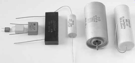
FIG. 20 A selection of 100nF non-polarized capacitors. Left to right:
63 V polyester, 400 V polyester, 630 V polycarbonate, 200 V silvered mica,
1500 V polypropylene, 500 V polytetrafluoroethylene, 2000 V mixed dielectric.
Although we will look at electrical safety in detail later, electrolytic smoothing capacitors should be considered during planning. The voltage on the can of the capacitor is indeterminate, but is generally near to the potential on the negative terminal. Although the can could be bonded to chassis if the negative terminal is at 0V, this invariably causes a hum loop, so the can is usually insulated from the chassis. The capacitor therefore has only a single layer of insulation between the HT supply and the outside world, but safety calls for either a double layer of insulation, or one layer plus an grounded metal shroud. (See later for explanation of Class I and II equipment.) Preventative maintenance means being able to see the signs of impending failure, and catching it before it goes bang. This is one reason for having all the power tubes clearly visible - if you spot a red-hot anode, you probably can get to the ''on/off '' switch before the fault destroys even more components. Intern ally, if all the components are clearly visible, you might spot a charring resistor or bulging capacitor before it destroys other components in addition to itself at the first application of power.
A rather more depressing aspect of preventative maintenance is to consider the consequences of failure of specific components.
When traditional electrolytic capacitors fail, they spray soggy paper and foil from their bases. Although modern capacitors are rather tamer and vent in a more controlled fashion, it is a good idea to consider where any vented material might land. It would be unfortunate if a failed LT capacitor vented a conductive spray over a perfectly innocent (powered) HT regulator PCB. Similarly, silicon rectifiers can sometimes fail explosively, and it would be particularly poor planning if the short-lived volcano was directly under a complex wiring loom. Although the author has not tested carbon resistors to destruction, industry wisdom is that they also fail pyrotechnically.
When you work on the amplifier, you will inevitably turn it upside down, so it is helpful if the taller and heavier components can be arranged so that they allow the chassis to stand firmly without rocking, and without tipping onto the delicate tubes.
Acoustical
It is unusual to consider acoustical problems in a power amplifier, but the input tubes are microphonic, and a flimsy chassis does not help. The author favors a rigid chassis with plenty of bracing, held together with plenty of large screws, even if the result is somewhat stronger than strictly required by the supported weight.
Tubes are microphonic because any movement of their control grid structure alters the local electric field and therefore the number of electrons reaching the anode. When the grid structure is placed closer to the cathode to increase mutual conductance, the same movement becomes relatively greater, so these tubes are intrinsically more microphonic, although their more rigid frame-grid structure often tames the problem.
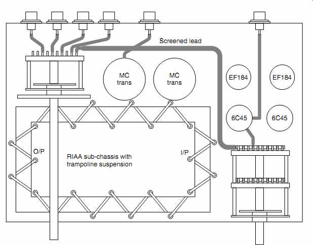
Pre-amplifiers may need deliberate acoustic isolation from structure-borne vibration, and anti-microphonic tube (valve) sockets with integral rubber suspension mounts used to be readily available. However, we still need to take wires to the tube (valve) base, and unless these are flexible, they form an acoustic short-circuit. A more effective way of achieving isolation uses knicker elastic to float a sub-chassis supporting an entire circuit in the same way that a trampoline is supported. Each anchoring point requires a small rubber grommet to prevent chaffing of the elastic and to prevent the elastic slapping metal when the sub-chassis moves (see FIG. 21).
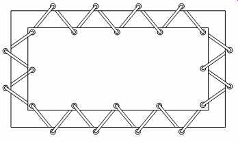
FIG. 21 Trampoline suspension of sub-chassis using knicker elastic
The internal mechanical resonances of a tube (valve) are typically above 500Hz [4], so these are the frequencies that need to be isolated. The suspended sub-chassis is effectively a 12 dB/oct low-pass filter with f_3dB at the resonant frequency of the suspension, so if it resonated at 63Hz (three octaves down), it would theoretically attenuate by 36 dB at 500Hz. In practice, damping in the springs reduces this figure, but best acoustic isolation is still achieved by minimizing the suspension resonant frequency. The resonant frequency is given by the standard resonance equation:
f = 1 2_
???????? Cm p
Where:
C=suspension compliance
m=suspended mass
Thus, deliberately adding mass (perhaps lead sheet) to the sub chassis can improve isolation. Although the resulting suspension is likely to be stiffer than an anti-microphonic tube (valve) socket, it is still important to minimize the number of wires to the sub chassis, use flexible wires, and dress them in loops that are large enough to avoid short-circuiting the suspension acoustically.
Air-borne vibration is far harder to eliminate. The ideal solution would be to enclose the circuitry within a solidly built closed box, internally lined with an acoustic absorbent such as bonded acetate fiber (BAF) or fiberglass building insulation. Unfortunately, there would then be no way for the heat to escape.
Aesthetic
Although placed last on the list, this consideration is probably close to the forefront of your mind as you will want to be proud of the results. The finished project does not need to look like a collision between a rat's nest and a supermarket trolley. Glowing glass is pretty, so almost all power amplifiers have their tubes at the front where they can be seen. And rightly so.
Form follows function, so right-handed people place the most important control (volume) at the right. Symmetry is usually pleasing, so a rotary input selector switch could be placed at the left. ''Retro'' looks are currently very much in fashion, so moving coil meters and hexagonal bakelite knobs are popular.
Blue LEDs are currently popular and will doubtless be considered to be deeply embarrassing in twenty years time. The author is rather fond of dual- color LEDs (red and green) with relative currents adjusted to give the same orange glow as a tube (valve) heater. If the green LED is powered from the heater supply, and the red from the HT, the LED performs a useful monitoring function as well as being pretty.
Practical examples
Application of the previous rules is best demonstrated by examples. Bear in mind that there are many ways of skinning cats, so if you can find a better solution, use it.
Power amplifiers
Let us suppose that we want to make a mono push-pull EL84 amplifier, perhaps a rebuild of a Leak TL12 +.
The major items to be positioned are:
- Mains transformer
- Output transformer
- Rectifier tube (valve)
- HT reservoir capacitor
- Output tubes
- Driver circuitry
Although negative feedback reduces hum, it would be best if there were no hum induced into the output transformer from the mains transformer. If we draw a line between the centers of the two transformers, and rotate them so that their coils are at 90 degr. to each other, this minimizes hum (see FIG. 22).
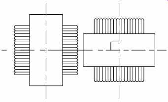
FIG. 22 Planning a layout: A. Output transformer and mains transformer
at right angles to minimize coupling.
We can also reduce induced hum by spacing the two transformers apart. As soon as we separate major parts, we ought to think about whether we can use the space in between them, perhaps for the HT reservoir capacitor. The reservoir capacitor draws current through the rectifier from the transformer in a train of 100Hz high current pulses (see FIG. 23).
The resistance of the capacitor/rectifier/transformer wiring loop should be as low as possible, so the ideal position for the rectifier tube (valve) is adjacent to the mains transformer, with the reservoir capacitor nearby. The center tap of the output transformer needs a low-impedance HT supply, so it should be close to the smoothing capacitor. If the HT capacitor is the traditional dual capacitor, it now makes sense for the two transformers to be moved apart just sufficiently that the rectifier and capacitor can be fitted in between with adequate room for cooling (see FIG. 24).
The capacitor is heated by radiation from the rectifier, but provided that there is a little separation between the two, the capacitor can cool by convection and only receives radiation proportional to the angle of arc subtended by the capacitor (see FIG. 25).
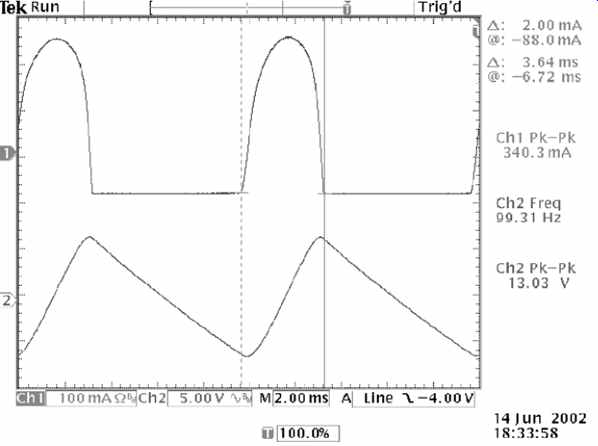
FIG. 23 Capacitor ripple current is typically 4-6 times DC load current
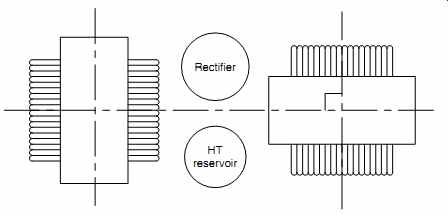
FIG. 24 Planning a layout: B. Adding rectifier and reservoir capacitor
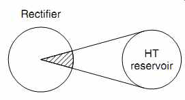
FIG. 25 Planning a layout: C. Radiated heat from rectifier to capacitor
The output tubes must be able to cool, so they should be separated by a distance of one and a half times the tube (valve) envelope diameter. But they also need to be reasonably close to the output transformer, and it would be convenient if they were also reasonably close to the driver circuitry. The logical position for the output tubes is thus on the side of the output transformer opposite to the rectifier, with the driver circuitry a little further beyond. The driver circuitry is now as far as possible from the mains transformer, and is partly screened from it by the output transformer. The two transformers have their coils aligned at 90 degr. to one another, but this can be achieved with either the coil of the mains transformer or the output transformer pointed at the driver circuitry.
Because the output tubes are widely spaced, even if the output transformer's coil axis is pointed away from them, they are likely to be in the leakage field from the edges of the coil. A separation of one tube (valve) envelope diameter from the output transformer significantly reduces the localized leakage field from the edges of the coil. This generalization works because larger tubes produce higher power and require a larger transformer. If the output tubes were beam tetrodes such as KT66, an even greater spacing might be desirable.
Given the previous caveats about output transformer orientation, it makes sense to align the mains transformer's coil at 90 degr. to the audio circuitry.
The tubes in the driver circuitry should be separated from the output tubes in order to keep them cool, and room is needed for their associated components, so moving them to the edges of the chassis allows their heater wiring to be pushed into the corners of the chassis, and coupling capacitors (which can often be quite large) can be conveniently placed between driver and output tubes. We have now arrived at the final layout (see FIG. 26).

FIG. 26 Planning a layout: D. Final layout
Readers who are familiar with the Leak TL12 + will recognize that this layout is much longer and slimmer than the original Leak. The Leak layout requires longer wires, but a square chassis is more accessible for wiring, so the reduced wiring time would have cut production costs.
Meters and monitoring points
Power tubes are inevitably used by circuits capable of destroying them. To illustrate this point, consider the output tubes in a power amplifier. They are connected to a substantial power supply via an output transformer having low DC resistance. If the tubes are cathode biased, the cathode resistor will protect them in the event of a fault, but grid bias provides no protection. Grid bias inevitably requires some means of monitoring cathode current.
If you are in a ''retro'' mood, you will fit a handsome round black moving coil meter and a rotary switch with a black pointer knob allowing each individual cathode current to be monitored, and if you are feeling really keen, you will add positions on the switch allowing key HT voltages to be monitored. The monitoring is important, so you will want to fit the meter and associated switch towards the front of the amplifier.
The meter has a stray magnetic field, so you won't want it to be close to beam tubes such as KT66, 6L6, KT88, or 6550 because it might affect screen grid current. The switch needs to be operated easily without obscuring the meter, and its selection and the meter reading need to be seen simultaneously, so they have to be mounted on the same plane. If you decide to put a meter and switch on the top of the chassis, make sure there's room to operate the switch without your fingers being burned by a nearby (hot) output valve.
Another possibility is to fit 4mm chassis sockets as low-voltage monitoring points, and it makes sense to put these sockets as close as possible to the voltage being monitored. Again, make sure you don't put them so close to hot tubes that you burn your fingers when connecting the lead from your DVM. If the amplifier is push-pull, output currents must be balanced, and you will probably want to be able to connect two DVMs simultaneously, so remember to provide a 0V test point for each DVM.
Alternatively, the traditional method was to use one meter to measure total current, and one to measure imbalance. Finding two suitable moving coil meters is tricky, but postage stamp sized DVMs that only need a ¼” hole for mounting are now readily available, so they can be fitted far more easily than a moving coil meter, or you could simply provide dedicated test points for total current and imbalance.
Sympathetic power amplifier recycling
Rather than build an amplifier from scratch, you might prefer to recycle an old amplifier's chassis and transformers, but use driver circuitry of your own design, saving an awful lot of metalwork (but not much money). If you take this approach, please do it sympathetically. Randomly gouging holes and leaving others unused looks unsightly - if it's worth doing to please the ear, it's worth taking a little trouble to please the eye (see FIG. 27).
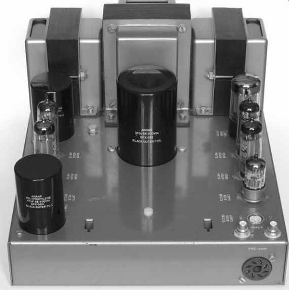
FIG. 27 Sympathetic recycling allows a new amplifier to retain its classic
looks
The amplifier started life as a Leak Stereo 20, but the coupling capacitors were leaky and the electrolytics had dried out, so the author decided to recycle the chassis with a simpler driver stage, using one less valve. This left a vacant ¾” hole, which was conveniently filled by a threaded DIN socket mounted on a small plate which was secured by the holes for the original B9A tube (valve) socket. Similarly, the holes for the original dual electrolytic capacitors were carefully enlarged for their polypropylene replacements, and a hole was punched in front of the mains transformer for the third polypropylene capacitor. The transformer links for selecting mains voltage and loudspeaker impedance were hardwired and their connectors replaced with blank panels. The transformers were mounted on 1/16-inch paxolin board to prevent leakage flux from reaching the (steel) chassis.
Classic amplifiers invariably had appalling connectors, ranging from lethal mains plugs to awkward loudspeaker connections, and this Stereo 20 was no exception. Fortunately, the hole for the large 3-pin Bulgin connector could be enlarged to take a flange mounting IEC inlet with integral fuse, and the hole for the mains outlets was enlarged to take an IEC outlet. Once unscrewed from the chassis, the tinned brass tags on the loudspeaker outlet boards were removed by squeezing their inside retaining lugs together using a pair of heavy duty pliers, allowing three-way binding posts to be neatly fitted. A blanking grommet masked the hole for the original mains fuse, and the hole for the switch cable was opened out to take a mains switch (see FIG. 28).

FIG. 28 A little ingenuity allows the fitting of safe and convenient connectors
Output-transformerless (OTL) amplifiers
The significance of an OTL amplifier is that the absence of an output transformer forces the output tubes to pass significant currents, and that these amplifiers often employ substantial global feedback, requiring unwanted voltage drops and stray capacitances to be minimized to ensure stability. The combination of these two factors requires true star grounding encompassing the entire amplifier and power supply, and this dominates mechanical design. As an example, a generic OTL headphone amplifier known at the Headwize forum as the Broskie-Cavalli Jones (BCJ) will be considered (see FIG. 29).
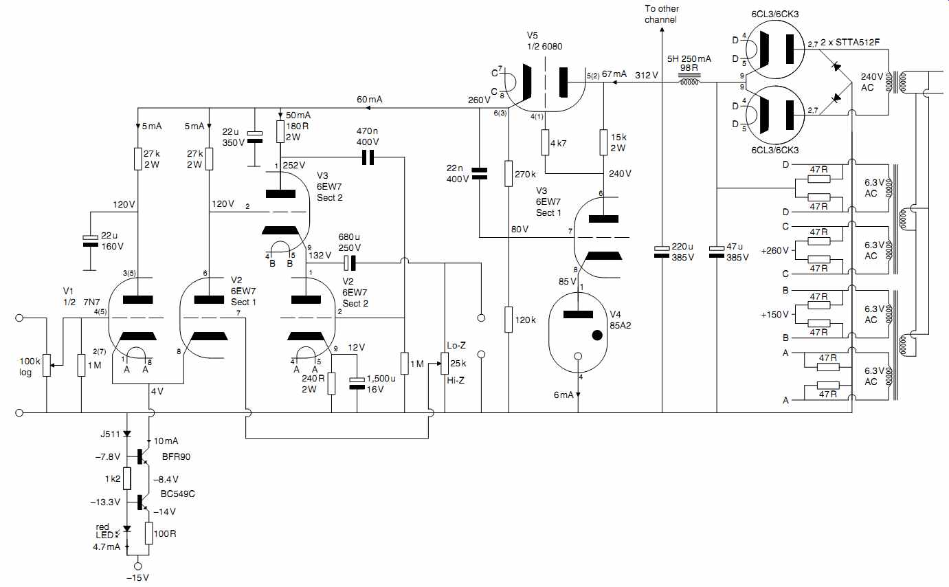
FIG. 29 Output-transformerless headphone amplifier
Despite initial appearances, the first two tubes are not a differential pair because the first tube (valve) has its anode decoupled to ground by a capacitor. The first stage is a cathode follower with a semiconductor constant current sink as its load. The output of the cathode follower is direct coupled to the cathode of the common grid stage, which is direct coupled to an optimized White cathode follower output stage [5]. User-adjustable global feedback to suit the particular headphone in use is taken from the output terminals of the amplifier to the grid of the common grid stage [6].
Because optimized White cathode followers develop their correction voltage across the series combination of the intentional regulating resistor at the anode of the upper tube (valve) and the output impedance of the supply, a regulator is almost mandatory, and because the 6080 is a twin triode, a separate regulator can easily be used for each channel.
All 0V connections from the amplifier and power supply must be brought back to the single star ground and each channel's regulated HT supply must also be a star point. These two requirements enforce a circular layout and all other design considerations are secondary (see FIG. 30).
The tubes must lose considerable heat, yet they are close together. The only way that this can be achieved is by mounting them on perforated sheet.
Pre-amplifiers
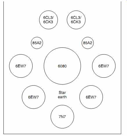
FIG. 30 Optimum star grounding dominates mechanical planning
Pre-amplifiers present different challenges from power amplifiers. It is unusual for the power supply to be on-board, and heat is far less of an issue. Conversely, signal levels are far lower.
A typical pre-amplifier might have five inputs selected by a front panel rotary switch. The traditional solution was to mount the switch on the front panel, and take each input up to the switch with screened lead (unscreened wire would cause hum and crosstalk problems). This was a very poor solution. Screened lead is expensive to buy and to fit, yet with five inputs, this solution only ever uses a fifth of the wire at any given time. The place for the input selector switch is on a bracket at the back of the pre amplifier, sufficiently close to the input sockets that unscreened wire can go directly from each socket to switch contacts.
The output of the selector switch feeds the volume control, so the obvious position is nearby, but it is often best positioned diagonally opposite (see FIG. 31).
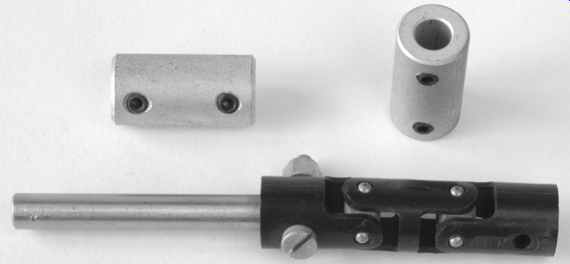
FIG. 32 Shaft couplers allow potentiometer or switch shafts to be extended
cheaply
The layout assumes a right-handed operator, so you might want to mirror it if you are belligerently left-handed. The selector switch is mounted at the back left, and extended to the front with a coupling and a length of 6mm or 1/4" shaft as appropriate. (13" lengths of stainless or silver steel rod are cheap at engineering suppliers.) If necessary, a coupling could be bodged from a short length of motorcycle fuel hose and associated Jubilee clamps, but a proper coupler is better (see FIG. 32).
This pre-amplifier has buffering between the volume control and its output, so this circuitry is logically best positioned at the back right, forcing the volume control towards the front of the chassis. This layout also assumes a moving coil RIAA stage using input transformers, and since they generally have flying leads, it makes sense to position them between the input sockets and the first gain stage, because it allows their (flexible) leads to link the (floating) sub-chassis to the connectors on the (fixed) main chassis. The RIAA stage is suspended on knicker elastic, and the necessary gap all around its sub-chassis allows cooling air past its tubes. The stage runs from right to left, so its output is close to the selector switch. The output of the selector switch to the volume control is a comparatively long run, so screened lead is necessary. An electrostatic screen could be added between the RIAA stage and the volume control, but this is probably unnecessary.
Umbilical leads
Since a pre-amplifier almost invariably has a remote supply, it needs an umbilical lead to connect the two together. To allow either item to be moved, the umbilical needs to be unpluggable.
The obvious solution is to provide a connector at each end of the umbilical lead. Once you have seen the cost of multipole connectors, you will quickly decide that a connector is only needed at one end of the lead. The problem is to decide which end of the lead should have the connector.
It makes better sense to make the lead part of the pre-amplifier rather than the power supply. The reason for this is that a pre amplifier tends to be designed for a specific application, per haps to match a particular cartridge in a particular turntable, and to drive particular power amplifiers. That being the case, its proposed physical positioning is also known, so required lead lengths are also known. The previous argument also applies to its audio leads, so why not hard-wire the outputs, rather than adding expensive and unnecessary connectors? Personality
A typical power supply provides a HT supply, one, or more LT supplies, and some means of remote power switching. All pre amplifiers need some, or all, of these facilities, so it would be very useful if a given power supply could be used by any pre-amplifier.
A pre-amplifier could then be quickly and easily replaced with out having to modify the power supply. One obvious consequence of this approach is that the power supply's multipole connector must be chosen so as to leave pins for future expansion and that extra connectors for future pre-amplifiers must be readily available at a later date. Thus, if you spot a bargain connector, buy as many cable plugs to fit the chassis socket as you think you will need for future pre-amplifiers. (Remember that the power supply's chassis connector must be a socket to make it impossible for your fingers to contact potentially live pins.) Pre-amplifiers often need elevated heater supplies to keep Vhk within acceptable limits in circuits such as cathode followers or cascode where a cathode could easily be at 200V. The required elevating voltages are determined purely by the pre-amplifier, so any circuit for elevating the heater supplies should be within the pre-amplifier chassis, not the power supply. In this way, the power supply's personality is determined purely by the pre-amplifier plugged into it, and it remains universal. Thus, all individual supplies (whether HT or LT) within the power supply should float from the chassis, so that their connections to chassis and to one another are determined purely by the associated pre-amplifier.
Mains/chassis ground has to be carried from the power supply to the pre-amplifier, and it is vital that this connection is reliable and of low resistance. If at all possible, use more than one pin on the connector to carry this connection -- this might mean that you need a larger connector with more pins, but it's safer.
We want a low resistance bond between the two chassis, so that implies a good cross-section of copper conductor in the umbilical lead. The best way of achieving this is to use an umbilical cable having a braided screen, and use the screen as the ground bond connector. If you make up your own cables, use two, or perhaps even three, layers of screens because this will not only ensure that there are no gaps in the composite screen but it constitutes a robust cable having a low ground resistance. By the time your umbilical has all this screening, plus a protective nylon braid over the top, it will be quite thick, so make sure that your chosen connector can accommodate and clamp the cable securely.
Power supplies
Fortunately, power supply planning is much simpler than that required for amplifiers. Nevertheless, the function of a power supply is to take AC mains, rectify it and deliver clean DC to another point. It therefore makes sense to lay a power supply out so that one end is deemed to be ''dirty'' (incoming AC mains, AC outlets, and rectification) and the far end ''clean'' (regulators, DC outlets).
Regulator positioning
The ideal position for a regulator is adjacent to the load because this minimizes unwanted voltage drops, yet there are powerful arguments against this positioning, particularly if the load is a pre-amplifier:
-- Regulators are inevitably hot, and pre-amplifiers should stay cool.
-- The raw input to a regulator is noisy.
-- Tube (valve) HT regulators require AC heater wiring, which is noisy. Obviously, semiconductor HT regulators do not suffer from this problem, and can be more easily placed adjacent to the load.
-- Tube (valve) heaters draw significant current, causing a voltage drop down the umbilical cable. However, a remote heater regulator can circumvent this problem because its output voltage can be adjusted to compensate whilst measuring the voltage at the tube (valve) pins.
Once these considerations have been taken together, the outcome is generally that the regulators are typically within the power supply, even though this does not at first sight seem to be ideal.
Professional power supplies often use remote sensing, also known as four-wire connection, so that each output terminal has a ''sense'' terminal associated with it which is connected to the (remote) load, thus automatically compensating for cable resistance. Although this technique requires extra pins on the connector and wires in the umbilical lead, the extra leads do not pass any significant current (see FIG. 33).
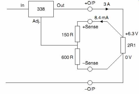
FIG. 33 Remote sensing overcomes the voltage drop down an umbilical cable
at the expense of two extra wires
Fitting mains outlets
Mains outlets are extremely useful, and allow the entire Hi-Fi to be switched on at the touch of a single switch. The most common (and safest) outlet is the IEC 10A 3 pin. The following points make life easier later on:
-- Align the sockets vertically. This uses space more efficiently on a slim chassis and allows more sockets.
-- Vertical sockets allow straight tinned copper wire buss bars to be threaded from pin to pin -- making wiring much easier and tidier.
-- Orient the sockets so that the live pin is closest to the chassis top plate rather than the open bottom. The dangerous pin is now buried deep inside the equipment where you are far less likely to touch it accidentally during testing.
-- Don't bother attempting to mark out the fixing holes. Once the hole for the body has been cut, an outlet can be inserted and you can mark the precise position of the holes with a scriber.
-- 3mm aluminum is thick enough to be tapped 4BA or M3.5 - but positioning nuts is fiddly. (Remember to lubricate the tap with methylated spirits.)
-- Provided that the holes are tapped, shuttered IEC sockets will just fit between the flanges of 200 channel if they are fitted vertically (see FIG. 34).
Fitting TO-3 regulators and transistors
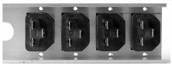
FIG. 34 IEC mains outlets will just fit vertically between the flanges
of 200 channel provided that the aluminum is tapped to take the securing screws.
Power supplies often need TO-3 style components to be fitted to the chassis. You don't need to measure and mark out all the holes precisely. Simply use the mica washer from an insulating kit as a template to mark out the holes. If you are using power transistors, they will be hot, so calculate how many watts of heat must be dissipated, assume a heatsink temperature of 50 degr. C (30 degr. C above ambient), and calculate whether you need a dedicated heatsink, or whether the chassis will do:
R theta= delta T q Where:
R theta =required thermal resistance of heatsink ( degr. C/W)
delta T=temperature difference ( degr. C)
q=power to be dissipated (W)
As an example, we might have an LM338 heater regulator passing 3A, with a drop of 6V across it, corresponding to 18W of dissipation. As a very rough approximation, if a reasonably large chassis has sides made of 2" x1" 3mm thick channel, at any given point, the channel has a thermal resistance of ~1 degr. C/W. Thus, mounting the regulator on the channel would keep the temperature rise to ~18 degr. C, resulting in a local chassis temperature of ~38 degr. C, which is acceptable. How ever, if two such regulators were nearby, the chassis tempera ture could easily exceed 50 degr. C, so it would be worth either fitting an additional finned heatsink or separating the heat sources by a few inches (50-70mm).
References
1. ''Microphone Engineering Handbook'' Michael Gayford (Editor). Focal (1994). ISBN 0-7506-1199-5.
2. ''Components Group Mobile Exhibition'' Brimar Tubes (November 1959).
3. ''Type KT66'' Osram Tube (valve) Technical Publication TP3. GEC (February 1949).
4. ''Mullard Technical Communications'' (November 1962).
5. ''The White cathode follower'' John Broskie. ''TubeCAD journal'' (October 1999).
6. A post by Alex Cavalli on page 5 of the ''Building the Morgan Jones" thread.
Further References:
''Noise Reduction Techniques in Electronic Systems'' 2nd edn. Henry W Ott. Wiley (1988).
''The technique of radio design'' E E Zepler. Chapman & Hall (1943).
''Foundations of Wireless (and electronics)'' 7th edn. M G Scroggie. Lliffe.
''Radio communication handbook'' 5th edn. Radio Society of Great Britain (1976).
''Electronic Classics'' Andrew Emmerson. Newnes (1998). ISBN 0 7506 3788 9.
