Other probes
Although the passive voltage-dividing probe reduced input capacitance from 120 pF to 12 pF, it is possible to do better.
Active voltage probes incorporate an amplifier at the probe tip and can reduce their input capacitance to ~2 pF, and because they incorporate an amplifier, no sensitivity is lost.
Current probes measure the current in a wire indirectly by measuring the magnetic field it produces, allowing current to be determined without breaking the circuit. They achieve this by directing the magnetic field through a coil of wire forming the secondary of a transformer, or they sense the field with a semiconductor Hall effect device. The passive transformer type cannot sense DC, but the active Hall effect type can sense DC at the cost of an amplifier and power.
Universal passive x10 probes are cheaply available for oscilloscopes with <250MHz bandwidth. Faster oscilloscopes need passive probes specifically designed for them if their band width is to be maintained to the probe tip, and such probes are typically ten times the price of a universal probe. Even worse, active probes are typically fifty times the price of a universal passive probe, and can be as much as two hundred and fifty times the price! Moral: Look after your probes -- the author keeps his probes in a plastic lunch box when they're not in use.
Oscilloscopes having automated measurement systems need to know that the signal has been applied via a probe. More sophisticated oscilloscopes have connectors/pins near the signal connector to set the appropriate scaling automatic ally, but some need to be told manually that a probe has been connected. Really old oscilloscopes require you to do the thinking and to remember to multiply the volts/div appropriately.
Transmission lines and terminations
The final way of connecting to an oscilloscope is via a 50 ohm RF transmission line, terminated by 50ohm at either end, and this is why faster oscilloscopes have a 50 ohm switch on their input coupling. If you accidentally operate this switch with a x10 probe connected, your signal will disappear. The other hazard with the 50 ohm termination is that the resistor has a very low power rating, so it can easily be burnt out if a large signal is accidentally applied directly to it.
Fortunately, transmission line effects do not become apparent until the cable length is a significant proportion of the length of one wavelength of that frequency travelling down the cable.
Since the velocity of propagation down most cables is 2/3 the speed of light (c=3x10^8 m/s), this means that one wavelength at 20 kHz occupies 10 km of cable. We can completely ignore transmission line effects in analog audio.
Oscillators and dedicated audio test sets
If you have an oscilloscope, you need an oscillator, but an oscillator is also very useful for supplying an external source of AC to a component bridge so that components can be tested at different frequencies. Air cored inductors are more easily measured at 20 kHz than at 1 kHz (XL =2_fL), whereas the primary inductance of an output transformer should be measured at 20Hz.
Traditional (Wien) oscillators
All analog oscillators contain three essential blocks:
-- An amplifier with positive feedback
-- A frequency-selective network
-- An amplitude stabilization circuit.
The amplifier could use tubes, transistors, or integrated circuits. The frequency selective network needs to be tuneable, and since no network can be continuously tuned over the entire 20Hz-20 kHz range, it is conventional to break that range into switched decades (20-200Hz, 200Hz-2 kHz, 2-20 kHz), and continuously tune over the resulting 10:1 ranges.
Traditionally, the most popular frequency selective network was the Wien network (see FIG.32).
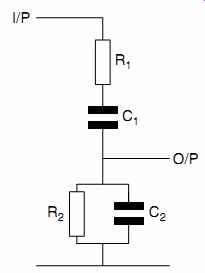
FIG.32 The Wien frequency selective network
The frequency of oscillation is given by:
In order to change frequency, we only need to change the value of one component. The loss of the network at resonance is:
The significance of this equation is that for the oscillator to maintain constant amplitude as we tune from one end of the range to the other, we must actually change a pair of values simultaneously, either the resistors must change together, or the capacitors must change together. Further, when we gang a pair of variable resistors or capacitors together, any tracking error causes the level to change with frequency. This deviation from perfection is known as range flatness. In general, it is easier to make tracking variable air-spaced capacitors than tracked variable resistors, so Wien oscillators usually use a dual-gang variable capacitor, but range flatness < +-0.1 dB is difficult to achieve. Variable capacitors can only have 180 degr. of rotation, so if you see an oscillator having a 180 degr. scale (rather than the 270 degr. achievable by a variable resistor), you can be pretty certain that you are looking at a Wien oscillator.
Although the Wien network can be connected around an amplifier, sustained oscillation requires that the amplifier's gain is only just sufficient to overcome the losses in the frequency selective network. If the Wien network uses paired components, it has a loss of 1/3, so the amplifier must have a gain of precisely 3. Although it is possible to trim the gain of the amplifier in the laboratory to produce oscillation, it soon drifts and oscillation stops. What is needed is a means of stabilizing the gain. The seminal Hewlett-Packard HP200 oscillator showed the way by using the change of resistance with temperature (and therefore applied voltage) of a fine tungsten filament isolated from external influences by placing it in a hard vacuum. In other words, it is used as a lightbulb to stabilize amplitude. At low frequencies, the temperature of the filament begins to track the waveform, increasing distortion, so thermally stabilized Wien oscillators rarely produce frequencies lower than 20Hz.
Summing up, a traditional Wien oscillator is likely to produce sine waves from 20Hz -20 kHz in three ranges with a typical range flatness of +-0.2 dB. Distortion is mainly dependent on the quality of the amplifier and can be made to be very low, although typical bench oscillators produce distortion ranging from 0.5 to 0.05% at 1 kHz, and rising at low frequencies.
Modern low-distortion oscillators tend to be based on the state variable filter.
Function generators
The Wien oscillator can produce a very low distortion sine wave, but an electronics laboratory often needs square waves or pulses. An alternative way of producing oscillations is to charge a capacitor from a constant current source (producing a rising ramp) until it reaches an upper threshold voltage, then immediately start discharging it with an equal and opposite constant current source (producing a falling ramp). When the falling ramp reaches a lower threshold voltage, we start the cycle again. The oscillator thus produces a triangular wave.
The oscillator is very versatile because not only does it produce the triangular wave, but it also produces a square wave and can produce a sine wave.
Because the sine wave is derived from a triangle wave, it always contains significant distortion, and 1% THD is typical.
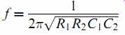
The distortion can often be seen at the tip of the sine wave, where a Norman arch appears rather than a soft arch (see FIG.33).
FIG.33 Comparison of low distortion sine wave (lower amplitude) with
sine wave generated by function generator (higher amplitude). Note the Norman
arch produced by the function generator
You might wonder why we should waste any time considering function generators for audio when they have such poor distortion, but even the very cheapest function generator has two very valuable qualities for audio:
-- They produce good quality square waves (sharp edges and negligible ringing) that are good for testing amplifier stability.
-- They do not require ganged controls to change frequency, so their range flatness is intrinsically perfect, making them excellent for critically measuring amplitude against frequency response of amplifiers.
As an example of the second point, the author was unable to detect any range flatness errors on his cheap function generator even though his dedicated audio test set can indicate 0.02 dB errors clearly.
Dedicated audio test sets
Neither a function generator nor a typical bench oscillator is ideal for audio testing. Fortunately, dedicated audio test sets are available second-hand.
An audio test set should contain at the very least:
-- A fairly low distortion (<0.05%) sine wave oscillator (typically 20Hz-20 kHz)
-- A wide-band meter calibrated for reading sine waves
-- A simple form of total harmonic distortion (THD) measurement
-- A peak program meter (PPM) for measuring noise.
Better test sets may include noise and/or wow and flutter (W&F) measurements. However, the main advantage of audio test sets is that they have meters scaled directly in dB, and can therefore measure audio frequency responses quickly and precisely.
When we looked at AC measurements, we saw that there were various options for specifying an AC waveform:
-- Rectify the waveform, apply the resulting DC to a mean reading meter, and calibrate it to VRMS of sine wave. This rectifier is ideal for driving an expanded scale having a range of only 1 dB because it averages noise to zero, improving accuracy, but it is only suitable for measuring sine waves.
-- Use a rectifier that produces an output that genuinely is proportional to VRMS and apply it to the meter. This rectifier is appropriate for power and distortion measurements.
-- Use a rectifier that captures Vpk (both positive and negative), and uses a meter with ballistics that not only display short peaks accurately (fast attack), but allows them to be read (slow decay). This approach is exemplified by the PPM and is appropriate for music and noise.
Because different measurements require different rectifiers, dedicated audio test sets incorporate all three rectifier types and they are selected as appropriate. Thus, a test set might have a moving coil meter having a sufficiently fast response time to meet the PPM attack specification (the slow decay is produced electronically) and driven by a peak-reading rectifier. To measure sine wave amplitude, a mean reading rectifier would be substituted, the meter ballistics would be slugged electronically, and the scale might be expanded electronically to make measurement easier. Finally, to measure distortion, the expanded scale and slugged ballistics would be retained, but an RMS rectifier would be substituted because this sums harmonic powers correctly.
For simple amplitude measurements, the meter section is simply a meter/rectifier preceded by a calibrated amplifier. To measure harmonic distortion, a filter must be added to reject the fundamental. We want to measure the level of the harmonics, but must reject the fundamental without affecting the level of the 2nd harmonic, which is one octave higher in frequency than the fundamental. This can be done in one of two ways:
-- Use a high-pass filter. Since the 2nd harmonic is an octave higher than the fundamental, if we want to measure THD to 0.1% (-60 dB), we need a filter with a slope of 60 dB/oct, or more. This is achievable, but not easy, and such a filter is unlikely to be tunable for different frequencies, so this approach leads to a test set that can only measure distortion at one or two fixed frequencies.
-- Use a notch filter. Active notch filters can easily achieve rejection of 80 dB, or more, at their notch frequency, but need precise tuning to achieve maximum rejection. Once auto-tuning has been added to maximize rejection, it is a small step to make the filter tuneable over a wide range, and this more modern approach leads to a test set that can measure distortion at any frequency, probably to better than 0.01% (-80 dB).
In the UK, there is a variety of test sets (mostly ex-BBC) available at prices attractive to the amateur, but it should be remembered that there is almost always a reason for test equipment being cheap:
-- BBC ATM1 plus TS10: Valve based, and both are usually lethally packaged. Don't even think about them. The Wien oscillator Tone Source (TS10) has poor distortion, The Audio TestMeter (ATM1) has superb attenuators and the (separate) mean/flat meter has very low stiction, but the amplifiers are noisy, and it can't even measure THD without external assistance. The PPM movement has incorrect ballistics, and PPM1 to PPM2 is 6 dB, rather than 4 dB.
-- BBC EP14/1: This was the first IC-based BBC test set, and includes a PPM for noise measurement. It is a true piece of laboratory equipment; using the expanded scale enables repeatable measurements to an accuracy of 0.05 dB. The THD measurements down to _0.1% can be made at 100Hz and 1kHz but a mean rectifieris used, rather than RMS. The Wien oscillator has somewhat a poorer distortion than the meter.
-- Ferrograph ATS1: An idiosyncratic, but very versatile, piece of test gear. Designed (predictably, as Ferrograph made some quite nice tape machines) for comprehensive testing of tape machines, it also includes W&F measurement, but not a PPM. Oddly, it tends to be quite a lot more expensive than the BBC alternatives.
-- BBC ME2/5: A ''cooking'' piece of test gear designed to replace the EP14/1 in less critical usage. The oscillator is digitally synthesized and can sweep frequency (intended, but never used, for automated music line testing). The meter section is only accurate to 0.1 dB but contains a primitive digital frequency meter. The unit is newer, smaller, lighter, more expensive, less accurate, and less reliable than the EP14/1.
-- Technical Projects MJS401D and Neutrik derivatives: A splendid piece of equipment with a wide bandwidth meter section far better than the EP14/1, including THD measurement at any frequency, accurate frequency meter, and comprehensive filters and rectifiers. Check for 1 kHz distortion at +20 dBu; with the 20Hz-22 kHz filter selected, it should typically better 0.002%. Commendably, Neutrik willingly repairs these test sets, even though they may be considerably more than ten years old. Options may add W&F, IMD. Later versions include a phase meter (very useful), so price may be variable; expect it to cost significantly more than an EP14/1, but perhaps need attention. Thoroughly recommended, but balance is a slightly questionable owing to electronic rather than transformer balancing.
-- Lindos LA100: Not (yet) available at amateur prices, this is an excellent piece of semi-automated portable equipment with an LCD display rather than a moving coil meter. It indicates to 0.01 dB, and under optimum conditions can measure distortion (at only five frequencies) to _0.005%.
Excellent for fast routine testing of tape machines. Includes everything previously described, and more (except real mechanical PPM and transformer balancing). Can talk to printers and PCs. Super. (Rechargeable batteries are included, but they typically die after five years. When they die, they crash the firmware - so just remove them.)
-- Audio Precision System One: An amazing piece of test equipment best used for production testing. Outstanding measurement ability combined with stunningly poor user-friendliness when used for one-off measurements. Needs a PC to drive it, but all its results are therefore available as files. Appalling ergonomics aside, the author would love one.
Professional audio equipment is inevitably balanced, so test equipment is designed to interface with balanced audio. Traditionally, transformers were used, but electronic balancing is now common, which can cause problems when connected to unbalanced equipment. The problem usually occurs at the output of the oscillator. The balanced output is often provided by a pair of unbalanced amplifiers producing signals referenced to ground, one producing one phase, and the other the inverted phase (see FIG.34).
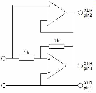
FIG.34 An electronically balanced output is often simply a pair of op-amps,
one inverting, one non-inverting Because the output is referenced to ground,
hum loops can occur.
This isn't a problem in a balanced system, but when an unbalanced output is taken, it can cause problems. The scaling on an oscillator's attenuators refers to the voltage between the two balanced conductors. If we only use one output, the output is half the amplitude (_6 dB). It is easy to forget this and calculate gains incorrectly. Equipment using transformer balancing has neither of these problems - if we want an unbalanced source, we simply connect one phase to the groundy input of our amplifier under test.
Most audio test sets have a meter section monitoring output typically called ''oscilloscope'' or ''listen''. This output is extremely useful when measuring noise or distortion. Listening to the character of the noise on headphones can often give clues as to its origin (using a loudspeaker often provokes acoustic feedback).
When measuring distortion, the signal at the monitoring output is the distortion waveform that can be taken to an oscilloscope.
Incorrect bias in a Class AB amplifier stage causes sharp cross over distortion spikes, so monitoring the distortion waveform can be a very quick way for setting bias correctly.
Even better, if the monitoring output is taken to an oscilloscope or computer soundcard that can perform an FFT, the spectrum of the distortion waveform can be investigated. The author finds the ability to analyze distortion invaluable during the early stages of audio design. As an example, the type 76 triode has a very good reputation for low distortion, so a batch was tested. Pleasingly, they produced _6 dB less distortion than a typical 6J5 under the same conditions. However, the FFT quickly revealed that unlike the 6J5, the 76's harmonics did not decay quickly (see FIG.35).
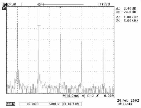
FIG.35 This FFT shows the distortion spectrum from 2nd to 6th harmonic
of a mu-follower using a 76 as the lower value and triode-strapped D3a as the
upper.
Note that the levels of the 2nd and 3rd harmonics are comparable
A cheap, but slower alternative to using the FFT to analyze the distortion waveform is to take the monitoring output to a wave analyzer. A wave analyzer is effectively a meter preceded by a radio that can be tuned to audio frequencies. Thus, it can be tuned through the distortion harmonics and measure their individual levels. Wave analyzers are available second-hand very cheaply, but tend to be quite bulky.
Other test equipment
Most electronics engineers would regard a multimeter, and oscilloscope, and an oscillator to be the absolute minimum required test equipment, but the following is a small selection of other items useful when building and testing tube amplifiers.
Component bridge
A component bridge allows you to measure capacitors and inductors accurately. This is particularly useful when building filters or equalization networks, and allows you to remove initial component value as a source of error. Component bridges also measure resistance, and are often more accurate at measuring low resistances than even an expensive digital multimeter.
The Marconi TF2700 is an excellent instrument, and you will see it advertised in the electronics magazines for a very reasonable price second-hand. It uses a single PP9 battery, and current consumption is so low that it is not worth the bother of making a mains adapter. It will measure capacitance (0.5 pF-1100 mF), inductance (0.2 mH-110H), and resistance (10mOhm - 11 M-ohm) to a basic accuracy of _1%. It can indicate loss factor of capacitors (very useful), and can measure air-cored inductors - digital bridges often can't. The circuit is very simple so it can be fixed easily if it develops a fault.
Even better, the accuracy of the TF2700 can easily be improved. The main range switch uses 0.5% tolerance resistors, most of which can be replaced by 0.1% metal film resistors, but the 10-ohm resistor must be replaced by a 0.1% non-inductive wire wound resistor. The coarse balance switch already uses 0.1% resistors, so no changes are necessary.
The final error comes from the position of the dial on the fine balance variable resistor, and reducing this error takes a little more time. You need four 200 kOhm 0.1% resistors and a 100 kOhm 0.1% resistor. If these are all wired in series, with the 100 kOhm at one end, you can pick off values from 100 to 900 kOhm in 100 kOhm steps.
Measure each of these values with the main range switch set to 10M. This forces the coarse balance control to be set to zero, and puts the onus of measurement on the fine balance control.
If you now plot a graph of measured value against known value, and draw a line of best fit through it, you will quickly see how much rotation the dial requires to minimize errors.
Assuming that the internal 100 nF 0.1% standard capacitor is not in error, the combination of replacing the main range switch resistors and fine dial adjustment usually reduces errors from +-1 to +-0.25%.
Voltstick
These have various brand names and are incredibly useful.
They usually look like a fat pen with a white tip. If the tip is near to mains, an internal LED lights (runs off 2xAAA batteries for years). They require no contact and are a lifesaver.
Always use them before cutting any cable that, potentially, could carry mains. They're very useful for checking the fuse in a mains plug because they can just be waved near the cable.
If the voltstick detects mains, the fuse must be intact - and it has been checked without needing a screwdriver to open up the plug and check for continuity.
Continuously variable transformer (variac)
A transformer does not necessarily need a secondary winding. It can perfectly well have a single winding that is tapped part way to produce the lower voltage, this is known as an autotransformer. Although an autotransformer is cheap, it does not provide isolation between primary and secondary. If an autotransformer were used to step 240V to 12V, but the neutral became disconnected between the mains outlet and the auto transformer, the full 240V would appear on the 12V circuit, with possibly fatal results. For this reason, the most common use of an autotransformer is the variable autotransformer, often referred to as a variac. A variac is a toroidal autotransformer with the tapping obtained by a rotating wiper that can move from one end of the winding to the other (see FIG.36).
Variacs are commonly used for applying power to equipment gently or for testing tolerance to mains voltage changes. There are various reasons for gently applying power to a device under test (DUT):
-- The DUT is newly built and not known to work. Bringing power up gently minimizes the smoke in the event of a wiring (or design) error.
-- The DUT has not been powered for years, and although it worked once, there is a suspicion that it may have developed a fault.
-- The DUT contains old electrolytic capacitors, that if gently re-formed by ramping power up over the course of 30 minutes, will subsequently be fine, but could fail with suddenly applied power.
Because mains voltage is not guaranteed to be exact, variacs are used to test that at the lowest expected voltage:
-- Regulators do not drop out of regulation
-- Power amplifiers deliver the specified power.
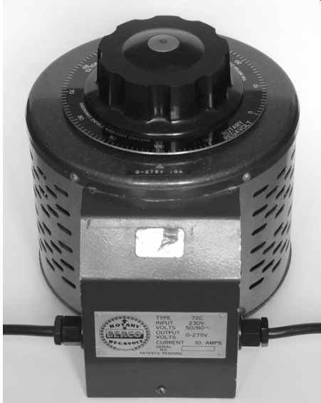
FIG.36 A 10 A variac is useful, if rather heavy
And at the highest expected voltage:
-- Devices dissipating significant power remain at an acceptable temperature
-- Devices with voltage limits such as capacitors or output tubes are still within their voltage limits.
In order to provide +10% output voltage, many variacs have a 90% tapping to which the incoming mains is connected. When the wiper reaches the 90% point, full mains is delivered, but as it sweeps past, the autotransformer steps the voltage up to a maximum of +10% (see FIG.37).
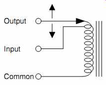
FIG.37 Applying the input to a tap part way down the winding allows a
variac to develop 0-110% output voltage.
A 50VA transformer could provide 50V@1A, 25V@2A, or 10V@5A, so the gauge of secondary wire is chosen to suit the expected current. Conversely, because a variac has a single winding of wire having constant diameter, the maximum load current is constant, so variacs are rated by their load current, rather than VA.
Variacs are commonly available second-hand, but they are frequently naked, requiring a case to make them safe. New variacs are available neatly cased with a mains outlet, complete with current and voltage monitoring meters, which can be very useful. If you have the choice, a 10A variac is much more useful (and very little more expensive) than a 2A version.
Valve tester
Valve testers are useful if you have a very large stock of tubes or are a keen designer and want to be able to make measurements enabling you to plot your own curves. However, it should be borne in mind that a universal tube tester inevitably exposes lethal voltages, so they are intrinsically dangerous, even by the relaxed standards of their day, and should be only approached with great caution. By definition, it is not possible to make a “safe” tube tester - the assumption was always made that they would be operated by people who were aware of all the dangers and were competent to deal with them.
Typical receiving tubes have heaters varying from 2.5V @ 2.5A (2A3) to 40V@300mA (PL519), with plenty of variation in between, so a tube tester needs a heater/filament supply to cope with this. One possible solution might use a variable regulated DC supply, but a supply capable of providing 40V would have to dissipate at least 94W when supplying 2.5V @ 2.5A, so the traditional solution was a tapped transformer.
Inevitably, there is considerable wiring between the transformer and heater/filament, and this can cause a significant voltage drop at high currents, so it is well worthwhile to check the actual voltage on the tube's pins.
Ideally, the supplies required by anodes and screen grids should not change their voltage under load. Typical tube testers can supply up to 400V at up to 100mA, and this is just within the bounds of a regulator, but a cunning solution was to use a tapped transformer to apply AC directly to the tube electrodes, and use the tube's self-rectifying action. The reason for not rectifying the AC directly was that rectification and smoothing inevitably worsen the regulation of the supply, whilst simultaneously adding expense. The current through the tube therefore consists of half-wave rectified pulses (see FIG.38).
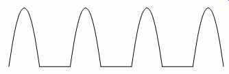
FIG.38 Valve anode current in scaled AC tube tester
We saw earlier that the inertia of a moving coil meter causes it to respond only to the DC component of a current. A full-wave rectified sine wave is composed of:
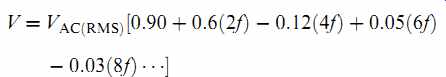
Thus the DC component corresponds to 0.90VAC (RMS), or, to put it another way, we require VAC (RMS) =1.11VDC. This is not a problem - we simply scale our anode and screen grid tappings appropriately, so that when we select Va =400V, the tester actually applies 444VRMS to the anode.
We can use almost the same trick at the grid, but we cannot allow the grid to go positive as the resulting grid current could damage the tube, so we half-wave rectify the grid bias voltage. (Full-wave rectification is not necessary because the tube cannot conduct on the missing grid half-cycle when the anode and screen grid voltages are negative.) Half-wave rectification halves the mean voltage compared to full-wave rectification, so when read by a moving coil meter, the control grid voltage should correspond to 0.555 of the claimed equivalent DC voltage. In practice, the calibration procedure for both the portable CT160 and the laboratory VCM163 specified a ratio of 0.52.
Grid voltage discrepancies aside, this measurement technique means that although the tube passes appropriate currents when conducting, it only does so for half the time, so the meter reading anode and screen grid currents needs to be calibrated to indicate double the current that would be indicated by an external meter.
Despite the previous caveats, the scaled AC technique makes it possible to take reasonably accurate measurements over a wide range at far less cost than a true laboratory test rig using pure DC supplies.
Although one use of a tube tester is to make sufficient measurements to be able to plot curves, the more common requirement is to investigate performance at a single point, perhaps to match tubes in push-pull output stages. When matching tubes, we must not only match anode currents (which we can already measure), but also match mutual conductance. Mutual conductance is a moving target, and because it changes with anode current, it is a small-signal parameter, so it should be measured by a low-amplitude AC voltage applied to the tube's control grid. A laboratory DC test rig could use any convenient frequency, but a scaled AC tester applies mains frequency plus a spray of harmonics to the grid, so a higher frequency is required, but not so high that Miller capacitance can cause a problem. In the VCM163, AVO chose to apply 15 kHz at ~270mVpk-pk to the control grid, sense the anode (or screen grid) current with a 10-ohm resistor, then amplify the resulting (rather small) voltage with a tuned amplifier in order to reject the (rather larger) mains related signals. Because this enabled accurate determination of mutual conductance at any operating point, it became known as a dynamic measurement. By contrast, earlier AVO testers made a static measurement of mutual conductance. They biased the control grid to ~1/2 V, measured the resulting anode current, and the meter current was then manually nulled using a “backing off” control. Finally, grid voltage was increased to +1/2 V and the increase in anode current could be directly read as mutual conductance in mA/V. Interestingly, the complete patent specification [1] mentions that using -1/2 V to +1/2 V doesn't give the right answer, but that if the voltage change is doubled from -1V to +1V, “the mutual conductance figure is substantially correct”.
A scaled AC tube tester produces test voltages that are directly proportional to mains voltage, so not only does the mains transformer primary need coarse tappings to set the tester to the nominal mains voltage, it also needs fine tappings that can be adjusted from the front panel to compensate for hourly variations. We can now draw a simplified diagram of a final generation scaled AC tube tester (see FIG.39).
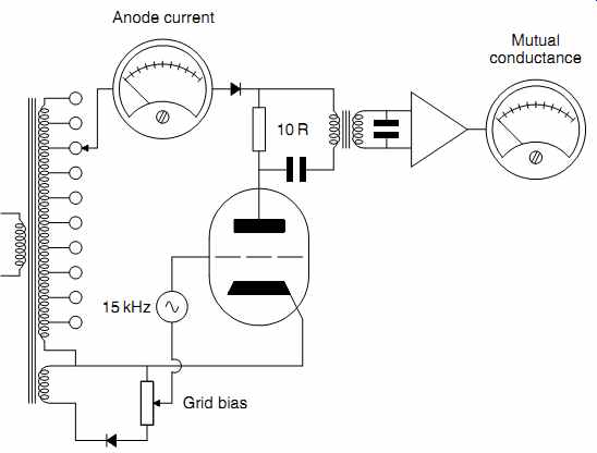
FIG.39 Simplified diagram of scaled AC tube tester
In practice, although the anode and screen grid are able to self rectify, AVO found that adding a series silicon diode prevented parasitic oscillations, so the voltage at these electrodes is already half-wave rectified.
When scaled AC testers were designed, mains demand was far less variable than it is now, and sudden current demands caused by half the population switching on a 2 kW electric kettle at the instant of the adverts part-way through a popular TV program just didn't occur. In short, scaled AC testers need their mains to be regulated if they are to be used for generating sets of curves.
Synthesized mains supplies with excellent regulation are avail able, but they are expensive (as much, if not more, than the tube tester). Constant voltage transformers can't be used because although controlled saturation of their iron core holds VRMS constant, it distorts the waveform and therefore invalidates the AC/DC relationships on which scaled AC testers are based.
The cheapest solution is a second-hand traditional AC voltage regulator based on a servo motor-driven variac.
Incidentally, if you have an AVO tester with a dirty electrode selection switch, they can be removed, stripped down, thoroughly cleaned, reassembled, and refitted. The job takes an entire afternoon, but if you opt to do it, take the opportunity to check and if necessary, correct an early design flaw in the rotor's phosphor bronze leaf springs, which should sit flush in a molded cavity, but some did not have cropped corners, so they sat proud and wore the adjacent rotor. As you reassemble the rotors onto the shafts, check that each one rotates freely in both directions and that the leaf springs don't catch.
AVO testers had double pole mains switches that are likely to be worn or have dirty contacts, possibly both, which can add significant (and variable) resistance in series with the tester, and significantly distort results. It's far cheaper and simpler to replace it immediately than have to diagnose it later as being the fault.
Since the modern use of tubes is primarily for audio, the voltages required are rather more restricted, so the scaled AC technique is no longer necessary. Rather than having many sockets wired in parallel with electrode connections selected by a large (and expensive) multi-pole switch, modern testers tend to have dedicated plug-in boards for each socket and removable wire links to select electrode connections.
Curve tracer
One of the uses of the tube tester was to generate data from which curves could be plotted, another was to match tubes at a particular operating point. If we had a machine that could plot curves directly, we could not only save time, but we could match tubes over an entire set of curves rather than at a single point. A curve tracer is effectively a low-bandwidth oscilloscope with fixed time base and a step generator instead of the trigger block, so comparison between one set of curves and another either requires a curve tracer with digital memory, or an analog tracer and a camera. (Traditionally, a Polaroid film camera would have been used, but a modern digital camera can do the job far more conveniently.) The most useful curves for a tube are the mutual characteristics (Ia against Vg), or the anode characteristics (Ia against Va). In each case, anode current is monitored and applied to the “Y” anodes, and a swept voltage is applied to the “X” anodes to produce a curve (see FIG.40).
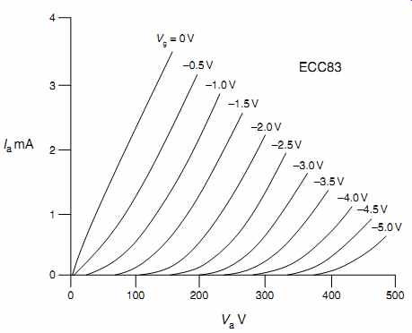
FIG.40 Valve anode characteristics
Since the swept voltage is applied to the ''X'' anodes and the tube simultaneously, it can have any waveform, and the cheapest waveform is a half-wave rectified sine wave derived from a mains transformer. Unfortunately, the half-wave rectified sine wave slows towards the end of the sweep causing uneven brightness when displayed on an analog oscilloscope, and other errors can cause the retrace (as the voltage returns to 0V) not to overlay perfectly. A ramp waveform plus blanking solves both these problems but requires a generator and power amplifier to feed the tube.
Ideally, we would like to produce a family of curves simultaneously, perhaps a complete set of anode characteristics for a 6080 power triode. To do this, we would need to sweep Va from 0V to perhaps 200V, supplying a current of up to 65mA (to limit Pa to the maximum allowable dissipation of 13W), requiring a power amplifier based on a HT regulator. In addition, we would need a step generator and high-voltage amplifier for Vg that quickly and repetitively sequences from 0 to ~80V in 10V steps to generate the individual grid curves (see FIG.41).
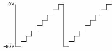
FIG.41 A repetitive stepped grid waveform enables a family of anode curves
The previous arrangement would display triode anode characteristics, but displaying pentode anode characteristics is some what harder. Measuring pentode anode current forces the current sense resistor to be in the anode circuit, but as the absolute voltage of this resistor is being swept from 0V to perhaps 400V, a differential amplifier with very good common mode rejection is required, whereas we could declare that Ia =Ik for the triode, and measure cathode current without worrying about a superimposed sweep voltage. The other problem with measuring a pentode is that when Va =0V, Ia =0, so the screen grid becomes an anode and passes the entire cathode current, yet its maximum dissipation is strictly limited. As a consequence, we cannot simply apply a constant voltage to the screen grid, it must be switched on only when the anode voltage is being swept.
Another problem is that as the anode voltage approaches its maximum, so does anode current, causing anode dissipation to approach its maximum, but a hot anode changes the tube's characteristics slightly. (This is one cause of retrace error in the half-wave rectified sine wave sweep.) To avoid this error, the sweep can be modified to consist of a series of short pulses having amplitudes that follow the path of the original ramp waveform.
As an example, if the anode voltage pulses caused anode current to be switched on for only 10% of the time, they would reduce anode dissipation to one-tenth of the continuous ramp.
The preceding thoughts only consider an analog curve tracer, yet they show that a curve tracer must be quite complex. Very few laboratories needed to buy a curve tracer, so the development cost had to be recovered over a small number of sales, and prices were stratospheric.
The question is, “Is it worth the price?” The answer to this sort of question is always personal, but the author's oscilloscope is switched on ten times as often as his digital transistor curve tracer, so the high prices commanded by geriatric tube-based analog curve tracers are staggering.
Despite knocking the amateur utility of a professional curve tracer, there is one instance where a tube curve could be useful, yet easily obtained. Suppose that you had a stereo push-pull triode amplifier that needed new output tubes, and you found a dozen new old stock (NOS) tubes in a dusty box at a radio fair for a song. From these tubes, you would like to find pairs, but you don't have a tube tester, or a curve tracer, yet you do have an oscilloscope and a junk box of transformers. A quick test set-up conveniently enables matching [2] (see FIG.42).
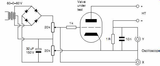
FIG.42 This test set-up by Alan Douglas [2] enables a single mutual characteristic
to be plotted by an oscilloscope
The set-up enables the entire mutual characteristic (Ia against Vg) of a tube to be determined for one value of anode voltage.
Since a power amplifier output stage operates with a fixed HT voltage, this sweep tells us everything we need to know to be able to pick pairs of tubes (see FIG.43).
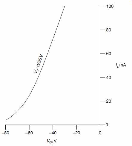
FIG.43 Plotting the mutual characteristic of Ia against Vg at the chosen anode
voltage enables easy matching of power tubes
Semiconductor component analyzer
This is a tiny handheld device with three leads and a dot matrix LCD screen that scrolls to give comprehensive information. It is incredibly useful for quickly determining the pin-out of a known component or identifying an unknown one, and can also be used for faultfinding if you don't mind removing components from their surrounding circuitry. Unfortunately, they are still quite expensive, so you will need to think carefully before buying one (see FIG.44).
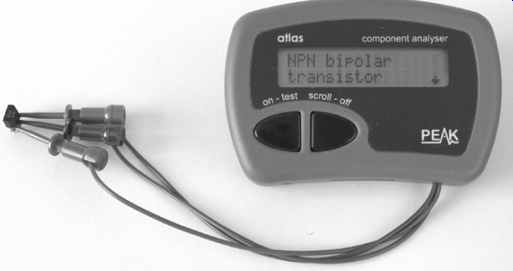
FIG.44 Semiconductor component analyzer
A handy constant current regulator
The author often needs a constant current regulator during testing and prototyping. The device is simply placed in series with any power supply and turns it into a programmable constant current source, so it only needs two terminals (see FIG.45).
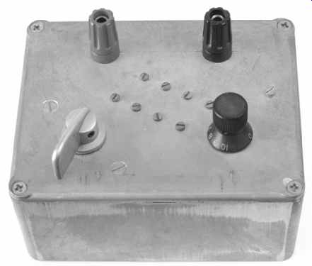
FIG.45 This device converts any voltage supply into a regulated constant
current supply.
The circuit is a modification of standard constant current heater regulator circuits, but with the addition of a multi-position switch and variable resistor it can very conveniently set any current between ~3mA and 1.5A, so it can be used for anything from plotting diode curves to powering “P” series tube heaters (see FIG.46).
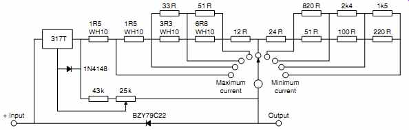
FIG.46 Circuit diagram of 3mA to 1.5 A adjustable constant current sink
The BZY79C22 diode protects the 317 from over-voltage and stored charge in the load. The 317 must be bolted to a heatsink, perhaps the aluminum chassis. The logarithmic range switch doubles current at each click, whilst the 25 kOhm variable resistor and associated 43 k-ohm resistor ensure that each range just overlaps the next. The entire circuitry can be very conveniently hardwired on the lid of a 6” x 4” x 2” diecast aluminum box, making it very easy to make or repair (see FIG.47).
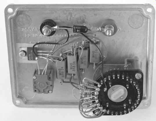
FIG.47 The components are hardwired onto the lid of a diecast box.
Audio phase meter
It is of ten useful to be able to measure he relative phase of two related signals. Traditionally, this was done by counting squares on an oscilloscope and scribbling numbers on the back of an envelope, but this is very inaccurate. A much handier method would be to have a circuit that produces a voltage directly proportional to phase and with reversible polarity to indicate lead or lag. Such a device would convert an ordinary DVM into a digital phase meter (see FIG.48).
The circuit is actually very simple, and is essentially an updated version of the BBC phase meter that was used for testing the equalization of stereo analog music circuits used for Radio 3 concerts. The 072 FET input op-amps allow a 1M input resistance suitable either for oscilloscope probes or for direct connection. The back-to-back Zeners protect the op-amps from over-voltage. The sine waves from the op-amps are passed to a pair of 311 comparators which convert them into square waves.
An XOR gate only produces a logic ''1'' when its inputs are different, so when the two square waves are 180 degr. out of phase, it produces a ''1'', and when they are perfectly in phase, it produces a ''0''. Because the change from 0 to 180 degr. changes the width of the pulse leaving the XOR gate, its mean level is directly proportional to phase. Mean level is found by dumping charge onto the 470 nF plastic capacitor. The voltage can now be read by a DVM, and is scaled by the potential divider to produce 180mV when the two inputs are exactly out of phase (180 degr.).
The D-type determines whether Ch2 lags or leads Ch1. If Ch2 lags, there will already be a ''1'' present when the positive-going edge of Ch1 triggers the D-type, so this ''1'' will be loaded to the Q output and remains there until the D-type is next triggered. The ''1'' (5V) drives a limited current into the base of the BC549, turning it on, and activating the relay which reverses the polarity of the 0-180mV phase voltage fed to the DVM, thus activating the DVM's +/- sign.

FIG.48 This circuit converts a DVM into a precision audio phase meter
-- All ICs to have power supply pins decoupled to ground via 100 nF ceramic
References:
1. ''An Improved Method and Apparatus for Testing Radio Valves'', Sydney Rutherford Wilkins & The Automatic Coil Winder & Electrical Equipment Company Ltd. UK Patent 480752 (1938).
2. ''Tube Testers and Classic Electronic Test Gear'', Alan Douglas. Sonoran Publishing (2000).
Addit. refs:
''Audio Measurement Handbook'', Bob Metzler. Audio Precision.
''Electronic Measurements'' 2nd edn., F E Terman and J M Pettit. McGraw-Hill (1952).