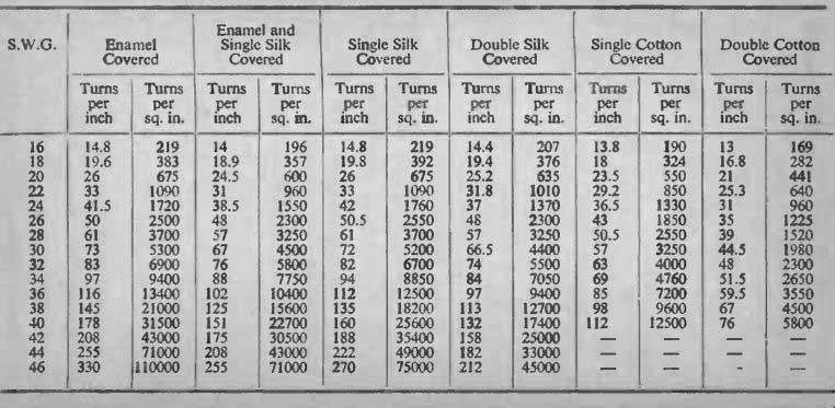
The table in this section enables the correct wire gauge to be chosen to get a given number of turns into a given winding space.
For each wire gauge, with its covering there appears two figures: the figure for turns per inch should be used for cases of layer winding, and the figure for turns per square inch for random winding. To illustrate the use of these tables, the wire gauges for each example given in the previous sections is worked out below.
Example 1.
The winding area in this case (see Fig. 1) is 0.275 sq. M.
It is required to get 6,300 turns into this space. This is equivalent to 6,300 - 23,000 turns per sq. in. 38 S.W.G. enameled only gives 0.275 21,000 turns per sq. in., so the next even gauge will be 40 S.W.G.
Example 2.
This is on the same size, but as the turns are fairly low, it should be possible to layer -wind it. Using 32 S.W.G. enameled gives 83 1.650 turns per inch. or just over 50 in a r layer. This requires -= 33 50 layers. At 83 turns per inch 33 layers will occupy a depth of 33 -= 0.39". If the paper used is 0.003" thick, 33 layers will take up 83 0.1", total 0.49". This allows enough for top insulation to make up 4".
Example 3.
Using the figure from Table 3, the winding space will be about I" x , or 0.33 sq. in. The turns will be 6,300 x 3.2 = 20,000.
20,000 This requires = 60,000 per sq. in. 44 S.W.G. enameled gives 0.33 65,000 per sq. in.
Example 4.
900 turns will again be layer-wound. Using 22 S.W.G. enameled gives 33 turns per inch, or 70 per 21" layer. 900 turns at 70 per layer requires 13 layers, say 14. as there will be very little clearance 14 14 layers at 33 turns per inch will take up -= 0.43". Allowing for 33 layer insulation will bring this to about 0.48". This leaves a good clearance. but it will probably be needed with a fairly heavy wire gauge and a long -shaped bobbin.
Example 5.
In this case there are two windings. one of 2,400 and one of 12.000. to be wound in a space of 0.86 sq. in. 40 S.W.G. enameled gives 31,500 turns per sq. in. Thus, 12,000 takes about 0.4 sq. in.
For the primary, 34 S.W.G. enameled gives 9,400 turns per sq. in., 2,400 so 2,400 turns takes up - = 0.266". Total area, 0.666". This 9,400 allows good margin for insulation.
Example 6.
In this case the two windings have to occupy 0.56 sq. in.
12,000 turns, as before, take 0.4 sq. in. in 40 S.W.G. enameled.
Using 42 S.W.G. enameled. 43,000 turns per sq. in., 12,000 turns take 12,000 = 0.28 sq. in. 4,000 turns of 40 S.W.G. enameled take 43,000
0.135 sq. in., total 0.415 sq. in.
Example 7.
Here, again, layer -winding will be used. For the 3,800 turns, using 36 S.W.G. enameled, 116 turns per inch gives about 156 per 3,800 layer (11"). This requires - - 25 layer. 25 layers will take 156 25
- = 0216" for wire, and at 0.003" per layer insulation, 0.075", 116 total 0.291". For the 220 turns. using 20 S.W.G. enameled. 26 turns per inch gives 35 per layer. 7 layers, taking up 7
-= 0.27" for wire, and 0.021" for insulation, total 0.291". Total 26 depth of both windings 0.582", which leaves room for insulation between windings and on top in a bobbin of depth 1" or 0.625".
Example 8.
Using the size from Table 2. Layer length E., depth I". Using 36 S.W.G. enameled for 1,850 turns: 116 x 1" or, say, 70 turns 1,850 27 per layer, gives -= 27 layers. Wire - - 0.233", insulation 70 116
0.081", total 0.314". Using 22 S.W.G. enameled for 74 turns. 33 X i" 4 or 20 turns per layer, gives 4 layers. Wire - = 0.122". insulation 33
0.012", total 0.134". Total winding depth 0.448" which allows room for insulation between and on top of the windings.
Example 9.
A I" waste -free will allow a layer length of 11-", and a total depth of 7/16". Using 34 S.W.G. enameled for primary windings:
960 Turns per layer, If, x 97-say. 130. Each half primary takes -, 130 or 8 layers (always take next whole number). Depth for ware 8
-= 0.083", for insulation 0.024", total per half 0.107", for whole 97 primary 0.214".
Using 20 S.W.G. enameled for secondary, giving 35 turns per layer, requires 3 layers, taking 0.116" for wire. 0.009" for insulation, total 0.125". Total depth for windings 0.339". Using 3 layers of 0.003" each between windings and on top, gives 0.027", total 0.366", which allows about 1/16" clearance on top.
Example 10.
Each quarter primary will use 4 layers of 34 S.W.G. enameled, taking 0.054" (including insulation). The half primary 8 layers taking 0.107", total for primary 0.215". Using 30 S.W.G. for the secondaries. 4 layers taking 0.068", total secondary space 0.136", total winding depth 0.351". Inter-winding insulation, as before, 0.045", total 0.396".
Example 11.
A 1" waste -free will allow a layer length of I", and a depth of 5/16". Using 38 S.W.G. enameled, 13 layers, with insulation 0.130". And for secondary. using 22 S.W.G. enameled, 5 layers, with insulation 0.167". Total, 0.297".
Example 12.
For the primary, using 32 S.W.G. enameled requires 10 layers, taking, with insulation, 0.150". For the secondary, 2 layers of 20 S.W.G. enameled will just fit in. This will take, with insulation, 0.083"; or, if another layer is required for the last few turns, 0.125".
Total, 0.275".
Example 13.
Here the winding space may be taken as 9/16" x 3/16", or 0.105 6.000 sq. in. 6000 turns of 46 S.W.G. enameled will occupy 110.000
0.055 sq. in. Allowing that only about 70% of such a small space can be utilized--i.e., 0.7 x 0.105 = 0.073 sq. in.-this leaves 0.018 sq. in. for the primary. If 200 turns are to go in 0.018 sq. in.. there 200 would be = 11,100 per sq. in. 36 S.W.G. enameled gives 0.018 13,400 per sq. in.
Example 14.
4,000 4.000 turns of 44 S.W.G. enameled will occupy or 0.057 71.000 sq. in. This leaves about 0.016 for the primary. If 700 turns go in 700
0.016 sq. in., there would be - 4,400 per sq. in. 30 S.W.G.
0.016 enameled gives 5,300 per sq. in.
------------
-------------
-------------
This table presents the nominal diameter and resistance (to four significant figures) of bare copper wire In various wire gauges. The gauges used are the Brown and Sharpe Gauge (B & S, also known as the American Wire Gauge, AWG), the Imperial Standard Wire Gauge (SWG) and the Metric Gauge.
The data are given in both English and metric units, the latter being Included for the benefit of overseas readers and Europeans who are not familiar with the other units. The diameter In the English units is expressed In mils, a mil being 1/1000 in.
The diameters and resistances given in the table are subject to normal manufacturing tolerances. A typical figure for the tolerance of the diameter 18 plus or minus I percent or 0.1 mil (.0025 mm In metric units) which ever is the larger. The resistance would be within plus or minus 2 percent at 20 degrees C but varies with temperature. The resistance changes approximately 0.4 percent for each degree C change in temperature, increased temperature giving increased resistance.
In the B & S gauge, the ratio of the diameter of any gauge number to that of the next larger gauge number is constant and is 1.1229. The corresponding ratio of cross sectional area Is 1.1229 squared, or about 1.2610.
This means that for each increase In gauge number, the resistance per unit length increases by approximately 25 percent. It is found that an increase in gauge number by 3 gives approximately double the resistance per unit length.
In the SWG the diameters of the gauge do not follow a simple rule but rather form a series of short arithmetical progressions. From ISSWG to 23 SWG, for example, the diameter decreases by 4 mils per number whereas from 23 SWG to 26 SWG it decreases by 2 mils per number.
In the Metric gauge the gauge number is ten times the diameter of the wire expressed in millimeters. The normally available sizes form a similar series to that of the SWG. Halt sizes in the B & S and SWG gauges (and Intermediate sizes In the Metric gauge) are available to special order If required.
These data are presented in such a form as to allow easy comparison of the different standards, permitting a near equivalent to be selected if coil winding data (for example) specifies a gauge which is not readily available. if 311 B & S were specified for a coil, It can be seen that either 42 SWG or 1.0 Metric has approximately the same diameter and could therefore be substituted.
----------- Nominal diameter and resistance measured at 20'C (68'F.)