A color receiver may be divided into sections for the purpose of study. One of these is composed of those circuits which are more or less similar to their counterparts in a b-w receiver. As we shall see, some of these circuits are almost identical to their b-w ancestors, while others have been modified extensively to meet the more demanding requirements of color reception. The remaining circuits of the color receiver have functions which are related specifically to color and have no b-w counterparts.
This lesson will deal principally with the circuits in the first category.
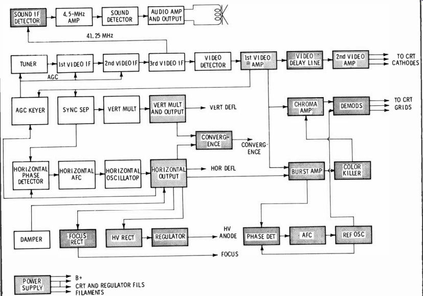
Fig. 1 is a functional block diagram of a color receiver. The circuits which are practically unchanged from their b-w counterparts are shown unshaded, those which have b -w counterparts but have been extensively modified are shaded, and those circuits which are peculiar to color are crosshatched.
Receiver Bandpass
Before discussing the specific circuits used in RF and video IF amplifiers of color receivers, let's consider the bandpass requirements of a color receiver as opposed to black -and -white. Present-day b-w receivers of good design usually have an overall response from the mixer to the video detector output that is 3 to 3.25 MHz wide at the 6dB points. This means simply that a video signal component at 3 MHz would produce only one-half the output voltage at the detector as one having a frequency of perhaps 2 MHz.
Typical color receivers of modern design have responses which are 3.58 to 4.0 MHz wide at the -6dB points. This is necessary to allow the color burst to pass through the IF strip and, more important, to allow the upper sideband of the color subcarrier to pass. From the first lesson, you will recall that the color burst has a frequency of 3.58 MHz and that the upper sideband extends to about 4.2 MHz. While it may appear that these frequencies cannot pass the IF strip, we shall see later that the relative attenuation of these frequencies in the IF strip is compensated by the tuned circuits of the chroma bandpass amplifier.
Still another requirement of the IF and RF bandpass of a color receiver is the shape of the curve.
Because of the tendency of the color subcarrier and the 4.5-MHz intercarrier audio signal to heat in the chroma circuits and produce interference in the picture, the output stage of the video IF must have excellent 4.5-MHz trapping. (The sound is recovered from a point preceding this trap.) It is also important that the slope of the IF response curve on each side of the lower -6dB point be constant so the overall response through the chroma amplifier will be smooth from 3.0 to 4.2 MHz.
RF Tuner
The function of the RF amplifier and mixer of a color receiver is the same as it is in a b -w receiver. It must tune to the 12 VHF channels and to the output of the UHF tuner with a reasonably constant noise figure across the band. However, the requirements for bandpass are more stringent, and the need for low noise is more pronounced in color, especially in fringe areas. Thus, a tuner which was entirely satisfactory for b -w reception might prove inadequate for color.
Although a tilt or sag in the response curve of a monochrome tuner might be compensated in the IF amplifiers, it is necessary to provide uniform response across the band for proper reception of color signals. A tuner having a response similar to Fig. 2 would produce excellent results in a color receiver.
It is interesting to note that since color receivers have become so popular, some of the manufacturers are adapting their color tuners to their black-and-white sets. Two examples of this are the RCA tuner Model KRK118 and Zenith tuner Model 175 -503.
With the exception of tube failures, both color and b -w tuners present only a moderate number of service problems. It is important. that the technician appreciate fully the necessity of accurate alignment and careful repair techniques when dealing with color tuners. It is possible to "repair" a tuner using slipshod methods or improper alignment procedures only to find that color reception has been seriously impaired even though b-w reception is reasonably good. Many of the compromises which have become common practice in b -w receivers cannot be made in tuners used in color receivers.
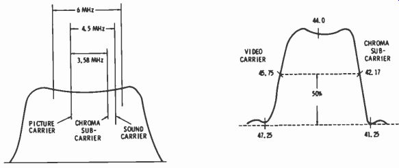
Fig. 2. Ideal tuner bandpass curve.
Fig. 3. Typical IF bandpass curve.
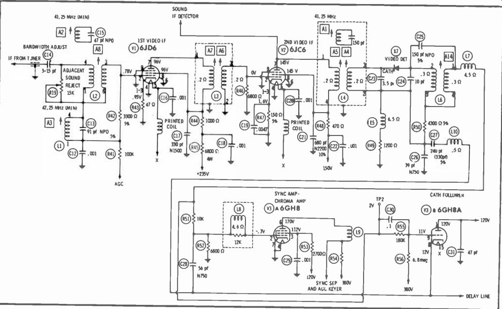
Fig. 4. IF amplifier and detector of RCA CTC 19 chassis.
Video IF Amplifiers and Detector
Although the function of the IF amplifiers in a color receiver is essentially the same as for a monochrome set, the bandpass requirements are more stringent just as they were in the tuner. First of all, the purpose of the section is to amplify and select a certain band of frequencies as shown in Fig. 3.
Notice that the sound carrier frequency is lower than the video carrier. This is due to the fact that the local oscillator in the tuner is tuned to a frequency above the channel and thus the sideband positions are reversed. The transmitted upper sideband becomes the IF lower sideband and vice versa.
In the past dozen or more years, the video IF amplifier has evolved from a very complex circuit with six stages of amplification to contemporary designs with, as few as two stages only slightly more complex than those used in present-day black-and-white receivers. The IF amplifier and video detector (RCA chassis CTCI9) shown in Fig. 4 is a typical two-stage circuit.
The mixer plate coil, L202, and the coupling transformer, L2, are tuned to approximately the center of the passband, and C14 controls the bandwidth of the combination by changing the amount of coupling.
When properly adjusted, these components produce a passband at the grid of VI having 6dB points at 42.17 and 45.75 MHz. A2 is a sound trap which attenuates the sound carrier and produces a "notch" at 41.25 MHz. The combination of the tuned circuit, L1 and C13, and R 19 form a second trap tuned to the sound carrier of the adjacent channel. Fig. 5 shows the actual bandpass curve seen at the plate of V1. At the time of observation, L3 was swamped and, therefore, had no effect on the curve.
L3 is the interstage coupling circuit between V1 and V2. It is a fairly conventional double -tuned circuit and is adjusted so that a symmetrical curve having a 3.58 MHz bandpass appears at the plate of V2 when the plate circuit is "swamped." The output of V2 is developed across two separate loads. The shunt -fed sound takeoff coil, L14, is resonant at the sound IF (41.25 MHz). The audio must be recovered in front of the video detector because the sound IF frequency is trapped out before video detection.
The remainder of the audio circuit will be discussed later.
The second plate load of V2 is L4 which consists of a double -tuned coupling transformer and a 41.25 MHz sound trap. The coupling transformer is overcoupled to increase its bandwidth and the two 45.75 MHz 42. 17 MHz slugs are adjusted for symmetry and bandwidth so that the video output appears as shown in Fig. 6.
Naturally, the sound trap (A1) is tuned to trap out the 41.25 -MHz sound carrier.
A final 4.5-MHz sound trap, A 14, is located in the output of the video detector. Notice that there is a total of three sound traps in the receiver. These are necessary to completely remove the 4.5 -MHz heat from the video section, as even a minute signal will heat with the chroma subcarrier in the color demodulator and cause interference.
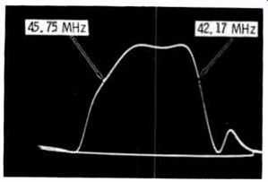
Fig. 5. Response curve at V1 plate.
The IF section of Admiral's I G 1 155-1. chassis (Fig. 7) is typical of the three -stage IF amplifier currently in use. The interstage circuit between the mixer plate and VI is similar to the circuit employed in the RCA chassis except that it does not have a 41.25-Mllz sound trap.
L4, L6, and L7 comprise a staggered triple with the three transformers single -tuned to 45.75, 42.5, and 43.8 MHz, respectively. Notice that the sound IF takeoff is from the last IF amplifier plate as it was in Fig. 4.
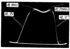
Fig. 6. Overall IF response curve.
The input to the video detector is trapped at 41.25 N Hz to attenuate the sound carrier, and a 4.5 -MHz trap in the output of the detector further attenuates the sound. Although it is not shown in Fig. 7, there is one more 4.5-MHz trap which is located in the grid circuit of the first chroma bandpass amplifier. Thus, both the Admiral and RCA have the same number of traps, one adjacent-channel trap and three sound traps, although their locations in the circuit are different.
Notice that the first and second IF amplifiers are "stacked." That is, the plate supply of the first tube is taken from the cathode of the second. This circuit is used in many receivers, both color and monochrome, and has the following advantages: (1) Since the plate voltage does not have to be dropped by a bleeder, the load on the power supply is decreased. (2) The second IF amplifier acts as a voltage regulator for the first IF stage to improve its stability and signal-to-noise ratio. (3) The AGC voltage which is applied to the grid of the first W amplifier is amplified and applied to the cathode of the second stage to improve the overall AGC action.
Referring once more to Fig. 4, there are two outputs from the video detector. One of these drives a.. cathode follower and its output ultimately reaches the CRT cathodes as the Y, or luminance, signal.
The second output from the detector drives a sync and chroma amplifier, and this amplifier, in turn, supplies signal to the sync and AGC circuits as well as to the chroma bandpass amplifier.
The video detector employed in the Admiral chassis (Fig. 7) has only one output which goes to the first video amplifier. Then the video signal is distributed to the sync, AGC, Y, and chroma circuits.
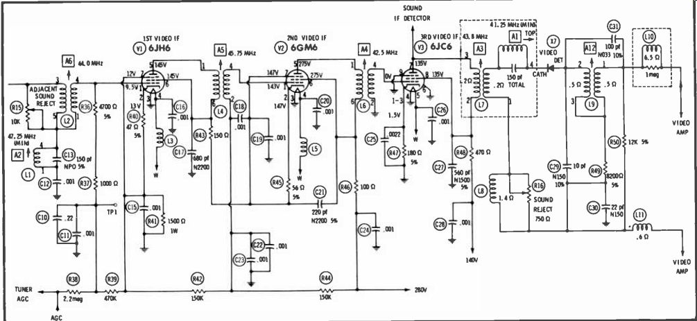
Fig. 7. IF amplifier and detector of Admiral 101155-1 chassis.
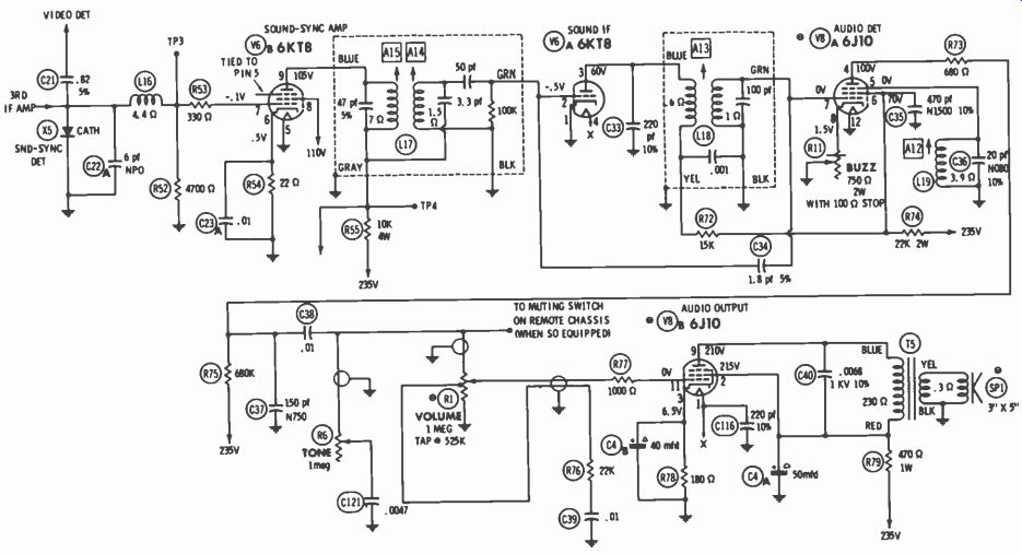
Fig. 8. Sound IF and audio section of Zenith 24MC32 chassis.
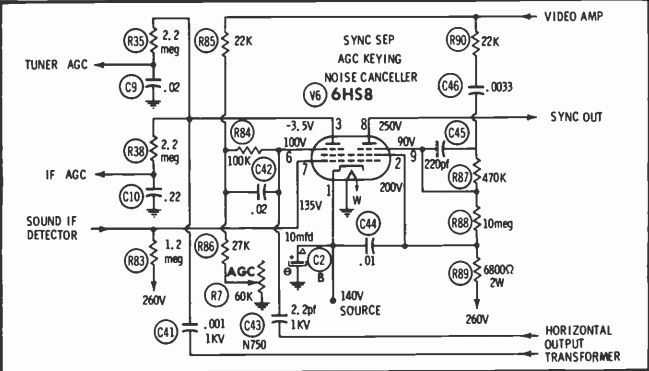
Fig. 9. AGC keyer, sync separator, and noise canceller of Admiral chassis.
Sound IF and Audio
Except for the point of takeoff and the separate sound IF detector, the sound system of a color receiver is essentially the same as those in monochrome receivers. The sound takeoff point in a color receiver is normally the plate of the final video IF amplifier because one or more sound traps following this point severely attenuate the sound signal before it reaches the video detector.
Fig. 8 shows the sound IF and audio section of Zenith Chassis 24MC32 . The 4.5-MHz sound signal, is developed by the sound and sync detector which is connected to the plate of the third IF amplifier. The detector output is amplified by V6A and the sync pulses are supplied to the AGC and sync circuits. The 4.5 MHz signal is amplified further in V6B and then detected by the quadrature detector, V8A. The remainder of the circuit is so familiar that no further explanation is warranted.
AGC and Sync
Although it is conventional in operation, the AGC circuit is very important in color reception since variations in signal level in the video and chroma circuits will cause the color of the image, as well as the brightness, to vary.
The AGC keyer, sync separator, and noise canceller circuit of the Admiral Chassis I G I 155-1 is shown in Fig. 9. During retrace time, the plate (pin 3) is supplied with a positive pulse from the high voltage transformer. At the same instant, a positive sync pulse is applied to the suppressor grid (pin 6). Also, at the same instant, a negative sync pulse is applied to the control grid; but its normal amplitude is insufficient to hold the tube in cutoff and k+e shall ignore it for the moment.
With both the plate and suppressor grid driven positive, V6 conducts and charges the top of C4I negative. Col tends to discharge between pulses, but the time constant during discharge is so long that the voltage remains substantially constant between sync pulses. Since the amplitude of the pulse applied to the plate is constant, the amount of charge on C41 is determined by the amplitude of the sync pulses applied to the suppressor grid and, of course, the bias set by the AGC control. Thus an increase in the amplitude of the sync pulses causes a greater negative charge to accumulate on C41 and this decreases the gain of the receiver.
If a noise spike should appear on top of (coincident with) a horizontal sync pulse, it seems that the charge on C41 would be excessively negative. This would cause a radical increase in AGC voltage and result in varying contrast on the CRT. To preclude this, negative sync pulses are applied to the control grid of V6. If a noise spike appears on top of the sync pulse, the tube simply does not conduct and the AGC voltage remains unchanged until the next normal sync pulse arrives.
The voltage developed on C41 has high -amplitude pulses superimposed on it and these must be filtered out before the voltage can be used for AGC. This is accomplished by the long time constants of R35, C9 and R38, C10. The sync circuit is conventional.
The right side of V6 remains cut out except when positive sync pulses are applied to its suppressor grid.
The sync pulses are amplified and inverted by V6 and fed to the deflection circuits. The control grid of 0.6 is common to both sides, and a noise spike "riding" a sync pulse also holds this side of V6 in cutoff.
As a result, one sync pulse does not appear at the output, but this does not cause the deflection circuits to fall out of sync.
Luminance Circuits
The main function of the luminance channel is to amplify the output of the video detector to a level Which is sufficient to drive the CRT cathodes. The channel may have one, two, or three stages depending on the video output level, the delay line loss, gain per stage, etc. Fig. 1 shows two stages since this number is a reasonable compromise among several modern sets.
While the luminance channel is similar in many respects to the video amplifier of a b -w receiver, it performs some additional functions. In many sets, the first luminance (or video) amplifier is used to amplify the signal fed to the sync and AGC circuits. In other sets, these signals are amplified separately or in conjunction with the sound IF signal.
Some manufacturers take the chroma signal directly from the video detector to the chroma bandpass amplifier while others take this signal from the output of the first video amplifier. The luminance channel also introduces a specific delay in the brightness signal, contains the brightness and contrast controls, and has means for setting the signal levels at each of the individual CRT cathodes.
Fig. 10 was chosen to illustrate the luminance channel because it performs all of the functions mentioned above. The output of the video detector passes through a 4.5 -MHz trap and a peaking coil to the grid of V4A. The level of the composite video at this point is approximately 2.5 volts.
Four outputs are derived from the plate circuit of V4A. A signal having a sync -pulse amplitude of 60 volts is taken from the bottom of L10 and fed to the chroma section. A 35 -volt signal from the bottom of R59 goes to the sync separator, and one having an amplitude of 20 volts goes to the AGC keyer. The fourth output is applied to the grid of V4B through L 12 and R61. These components reduce the high -frequency response to attenuate the chroma subcarrier side bands. A portion of the output of the vertical output tube is also coupled to this grid to provide vertical blanking. In modern color receivers, it is common practice to inject the vertical blanking pulse into the luminance channel.
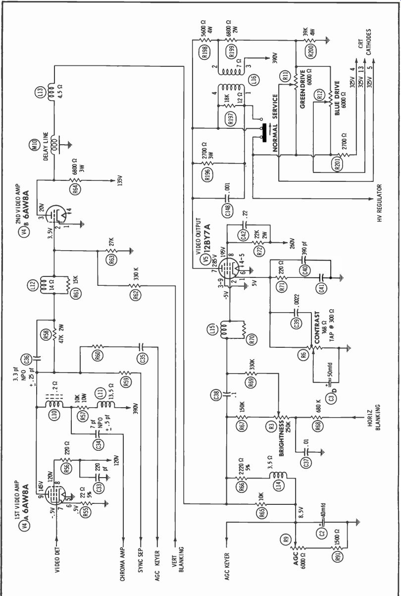
Fig. 10. Luminance channel of General Electric FY chassis.
The delay line driver, V4B, is a triode because a fairly low output impedance is required. The type of delay line driver varies among sets of different make, but it is characterized by relatively low output impedance. Notice that the plate load resistor of V4B is only 6800 ohms.
To drive the delay line, some manufacturers use a cathode follower, others use a bootstrap amplifier, and still others employ a transistor.
One characteristic of any amplifier circuit is that signals passing through it are delayed by an amount which is inversely proportional to the bandpass. Since the bandpass of the luminance channel is more broad than that of the chrominance channel, the transit time is about I microsecond less. If no correction were made, the Y signal would be presented on the CRT before the chrominance signal and the color would "trail" the black-and-white image approximately N/64 inches, where N is the width of the raster in inches.
Although the term "delay line" may be new to some technicians, all have worked with transmission lines and coaxial cables which are, in reality, delay lines. As we all know, the velocity of propagation (speed) in a line is less than it is in free space, and so any transmission line could be used as the delay line in the luminance channel. The velocity of an electromagnetic wave is 300 meters per microsecond in free space but only 200M/usec in RG59/U cable. Thus 200 meters (656 feet) of RG/59U would produce the desired delay.
A. lumped constant line.
B. Early -model delay line.
C. Modern delay line.
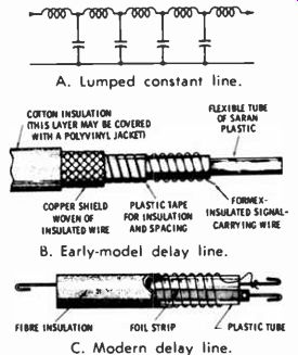
Fig. 11. Evolution of delay lines.
Unfortunately for the cable manufacturers, more convenient delay lines have been developed. Delay lines consisting of lumped constants (Fig. 11 A) have been used in many applications, but a "distributed constants" line is somewhat more economical. Fig. II B is a drawing of the cable used in an early General Electric receiver (Model 15CL 100). The inner conductor is wound around an insulating tube to increase its inductance, and a coating of powdered aluminum and styrene increases the shunt capacity. In this manner, a 1-microsecond delay is achieved in only 18 inches of this cable. Fig. 11C shows a more recent delay line which is only about 5 inches long.
Four signals are applied to V4 (Fig. 10). In addition to the delayed luminance signal and vertical blanking pulses, horizontal blanking pulses are inserted through R68 to the bottom of the brightness control. The brightness control determines the DC potential at the grid which, in turn, controls the plate voltage of V4 and, ultimately, the CRT cathode voltages. Notice that the lower ends of R65 and L14 are connected to the slider of the AGC control and the cathode of the AGC keyer. As the cathode bias of the AGC keyer tube is made more positive, the AGC voltages is decreased.
resulting in greater receiver gain and a darker picture. However, this same bias which is applied to the cathode of the AGC keyer is applied to the grid of V5. Thus, as an increased signal tends to darken the picture, the CRT brightness is automatically increased.
The contrast (video gain) control located in the cathode circuit of V5 functions in much the same fashion.
As the resistance is decreased, the contrast is increased and the plate potential is reduced. This reduces the CRT cathode potentials to increase the brightness.
The network in the plate circuit of V5 splits the signal into three separate signals which, in turn, are fed to the three CRT cathodes.
While the red drive is fixed, the blue and green cathodes are connected through drive controls to provide for gray scale adjustments. In the "service" position, the service -normal switch shorts the primary of L16 and removes the luminance signal from the CRT. (Another switch section is used to remove the vertical sweep.)
An output is taken from the common ends of R11, R12, and R201; and, after it is integrated or filtered, it is used as the control voltage for the high-voltage regulator. For example, if the brightness control is set for less brightness, the DC level of the CRT cathodes is made more positive. This increased positive level increases the conduction of the shunt regulator to compensate for the reduced conduction of the CRT. Thus, the load on the high -voltage power supply remains constant.
Some of the receivers which were checked incorporated some type of video peaking control in the luminance channel. This control changes the high -frequency response of the video amplifier to give a sharper or softer picture. If it is a back -of set control, it should be set according to the owners preference.
One important characteristic of all luminance amplifiers is often ignored by many technicians. Since all the stages in the channel are direct coupled, a. moderate change in voltage level at one point in the circuit may have drastic effects elsewhere. For example, suppose that R55 in the cathode circuit of V4A increases in value enough to make the cathode potential rise to 1 volt.
If this were a conventionally coupled amplifier, there would be very little change in operation since the tube would continue to function reasonably well with a moderate increase in bias. Not so in a chain of direct -coupled amplifiers! The increase in positive cathode bias will cause the plate voltage to rise.
Since the two succeeding plates are direct coupled, this change in level is amplified just like any other signal. The voltage gain from the grid (or cathode) of V4A to the CRT is about 40, so the .5 -volt change at the cathode of V4A will cause the CRT cathodes to change about 20 volts. The change at the CRT cathodes would be positive, so a noticeable decrease in brightness would result.
Because of this characteristic, it is very important to be sure that an abnormal voltage near the output of the channel is actually being caused by a component in that specific area. Often the cause of trouble is far removed from the point where the symptoms are first detected. It is sound practice to check back towards the input until a point is reached where everything is normal and then examine the components just after this point.
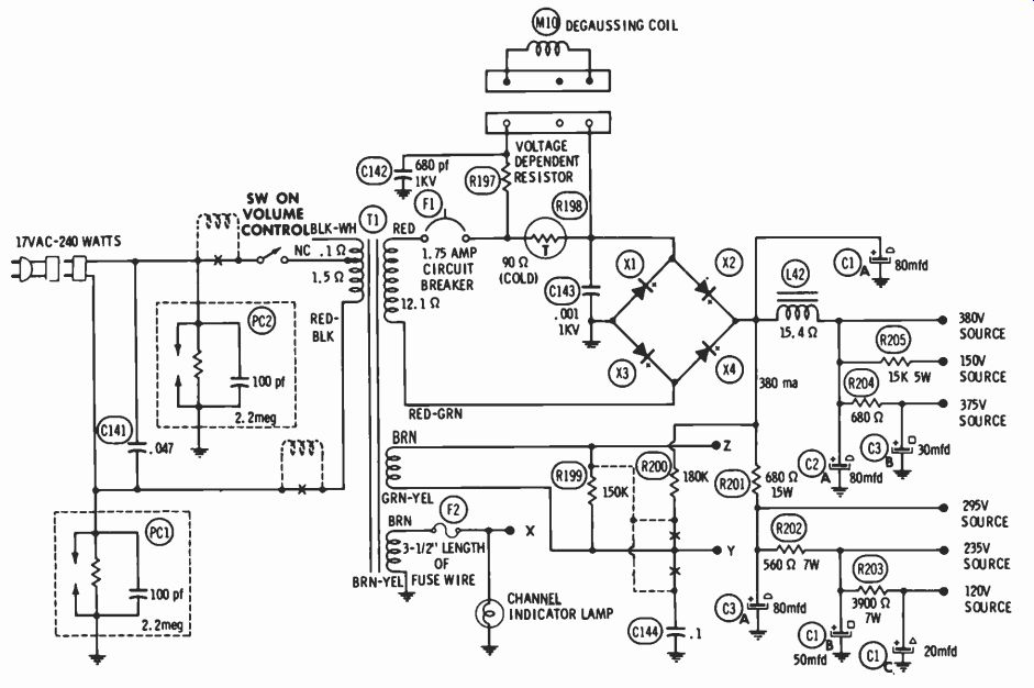
Fig. 12. Power supply of RCA CTC19 chassis.
Power Supply
The power supplies of color receivers are quite similar to those found in many b -w receivers. Fig. 12 is the power supply of the RCA CTC19 chassis. While this power supply uses a full -wave bridge rectifier, full-wave doublers are used by some manufacturers. Some receivers use B+ voltages as low as 280 volts, but a B + source nearer 400 volts is more popular. All the sets checked used a power transformer with a step-up winding for the rectifier and a separate filament winding for the shunt regulator and CRT. This winding is connected to B+ to reduce the heater -cathode potential of these tubes.
Nearly all present-day sets feature automatic degaussing and the circuit in Fig. 12 is typical. When the receiver is off, the resistance of R198 is high while the resistance of R197 is low. When the set is turned on, AC flows through the rectifier and the degaussing coil which are effectively in series. A small current flows through R198, causing it to become warmer. This warming action decreases the resistance of R198 and this decreases the voltage drop across M 10 and R197. R197 is voltage sensitive, that is, its resistance increases as the applied voltage decreases. The action of R197 and R198 is cumulative, and so the current through the degaussing coil falls to zero after a few seconds.
Summary
Referring to Fig. 1, the color receiver circuits may be divided into three groups. One group comprises those circuits which are similar or identical to circuits found in b -w receivers: tuner, IF strip and video detector, most of the sound circuit, AGC keyer, sync separator, and the deflection oscillators. The video amplifiers, power supply, high-voltage supply, and deflection output circuits have b-w counterparts; but these circuits have been modified extensively to adapt them for color. The third group includes the circuits which do not have counterparts in a b -w receiver.
These are the chroma circuits, sound IF detector, convergence circuits, video delay line, high -voltage regulator, and the focus rectifier.
The tuner and IF circuits are modified only slightly to increase the response near the upper edge of the video passband. Additional traps are required to prevent interaction between the 4.5-MHz sound carrier and the 3.58-MHz chroma information. The additional traps make it necessary to move the sound takeoff point "forward" and use a separate sound IF detector. Otherwise, the sound system is conventional. The AGC and sync circuits are nearly identical to the ones found in monochrome receivers.
The luminance channel performs the same functions as the monochrome video amplifier and also it has some additional features. It provides for video delay, performs the retrace blanking, incorporates the brightness control, and, of course, it drives three CRT cathodes instead of one. The luminance channel is direct coupled and this can lead to service problems for the unwary technician.
The power supply is essentially a "beefed up" b-w power supply.
The usual B+ output is about 400 volts with a current drain near 500 ma. Automatic degaussing is accomplished by the power supply as an additional function.