The Importance of a Schematic Diagram
A SCHEMATIC DIAGRAM shows the electrical connections of an electronic device, using symbols and straight lines to represent the parts and their connections.
Electronic Symbols
An electronic symbol represents the function of a part in a circuit, not its outward appearance. Table I gives a list of electronic symbols in general use, and the reference letters of the principal types.
Reference Designations
As shown in Table I, the principal types of symbols have reference letters. In a schematic all the components with the same reference letter are numbered in sequence from left to right, and downwards where two or more are equidistant from the left-hand margin, for ease of correlation with descriptions, instructions and parts lists. Symbols which represent different sections of a multiple component, such as a dual-triode vacuum tube, or a ganged control in which one knob moves two or more decks or sections, are given the same number, but the individual sections are identified by letter suffixes. For example,
----------------
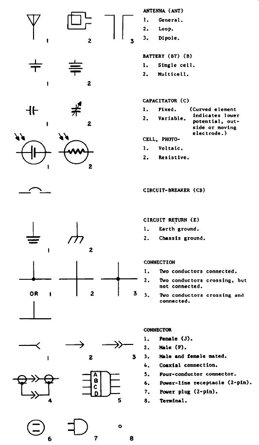
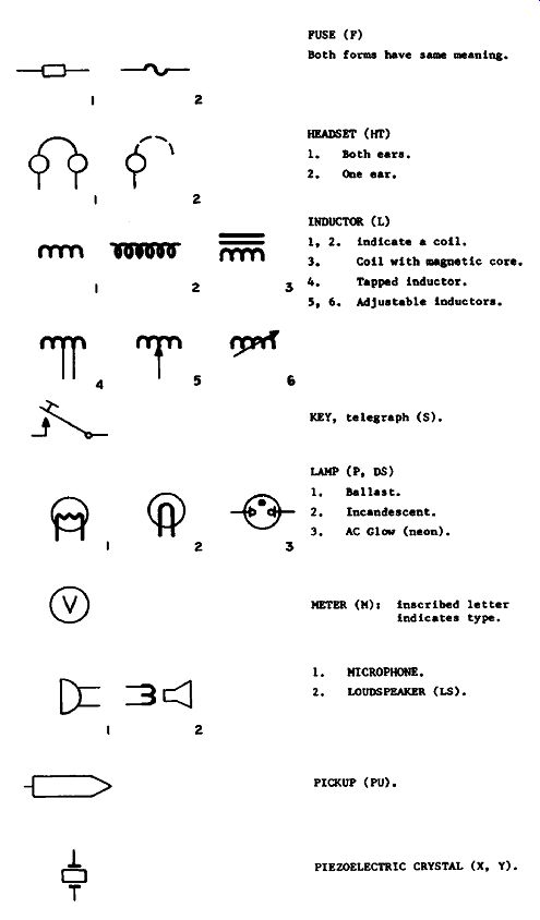
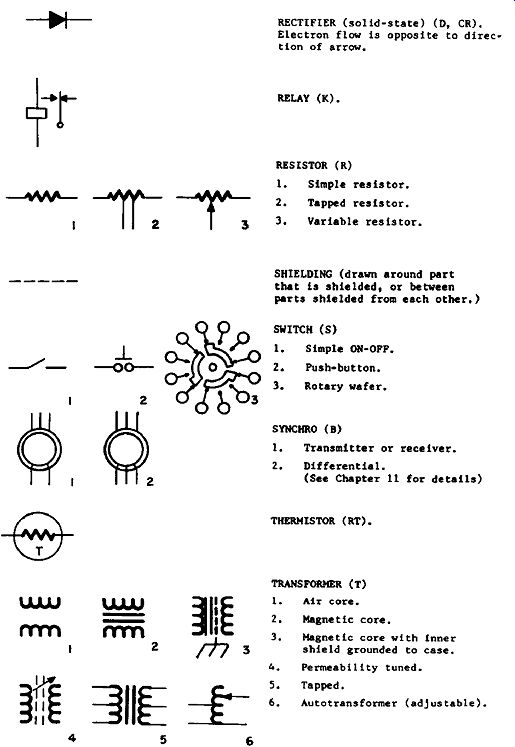


TABLE I SYMBOLS
2* Loop.
3. Dipole.
2. Multicell.
CAPAC1TATOR (C)
1. Fixed.
2. Variable.
CELL, PHOTO 1.
Voltaic.
2. Resistive.
(Curved element Indicates lower potential, out side or moving electrode.)
CIRCUIT-BREAKER <CB) CIRCUIT RETURN (E) I. Earth ground.
2. Chassis ground* CONNECTION I. Two conductors connected*
2. Two conductors crossing, but not connected.
3. Two conductors crossing and connected.
CONNECTOR 1.
Female (J).
2. Male (P).
3* Male and female mated.
4. Coaxial connection.
5. Pour-conductor connector.
6. Power-line receptacle (2-pln)* 7, Power plug (2-pin).
8. Terminal.
PUSE (P) Both forms have sane meaning.
HEADSET (HT) 1.
Both ears.
2, One ear* INDUCTOR (L) 1, 2« indicate a coll.
3. Coil with magnetic core,
4. Tapped inductor.
5t
6. Adjustable inductors.
KEY, telegraph (S).
LAMP (P, DS) 1, Ballast.
Incandescent.
AC Glow (neon).
METER (M): inscribed letter indicates type.
1.
MICROPHONE.
2. LOUDSPEAKER (LS).
PICKCP (PU).
PIEZOELECTRIC CRYSTAL (X, Y).
RECTIFIER (solid-state) (D, CR).
Electron flow is opposite to direction of arrow.
RELAY (K).
RESISTOR (R)
1. Simple resistor.
2. Tapped resistor.
3. Variable resistor.
SHIELDING (drawn around part that is shielded f or between parts shielded from each other.) SWITCH (S)
1. Simple OH-OFF.
2* Push button.
3. Rotary wafer* SYNCHRO (B)
1. Transmitter or receiver.
2. Differential.
(See Section 11 for details) THERMISTOR (RT).
TRANSFORMER (T)
1. Air core.
2. Magnetic core.
3. Magnetic core with Inner shield grounded to case.
Permeability tuned.
5. Tapped.
6. Autotransformer (adjustable).
TRANSISTOR (Q) I. PNP.
2. NPM.
J. UJT.
4. MOS/FET.
(Cicles may be omitted.) TUNNEL DIODE <D) VACUUM TUBE (V)
1. Triode.
Pentode.
Dual trlode In one envelope.
Gas regulator.
Thyratron.
Ignltron.
Picture tube.
Cathode-ray tube (CRT).
ZENER DIODE (D).
----------------------
... C2A, C2B and C2C would designate three sections of a ganged variable capacitor (see Figures 2.26, 5.10, 5.11 and 5.14 for examples).
Where a schematic diagram is broken down into subordinate sections because it is too large or complex to be shown on one sheet of paper, it is customary to use three-figure number groups starting with 1, 2 and so on, for each section (like the numbering of rooms by floors in a hotel). For example, C102, R115 and Q167 will all be in the first section, and R455, C407 and Q410 will all be in the fourth.
Schematic Analysis
Schematic analysis consists in separating the overall electrical picture into its parts, so as to determine their nature, function and relationship. It is a process like anatomy. The following sections will tell you about the " organs" found in schematic " bodies."
Individual Circuits
These "organs" are individual circuits. Taken separately, you’ll find each is easy to understand and recognize, because all circuits are laid out in a conventional way. The signal input is almost invariably from the left, the output to the right. This horizontal low takes place along two parallel paths (see Figure 1.3). The upper path is the "high" side of the circuit, the lower the "low." The low side is the return path, and is usually considered to be at zero or ground potential, even though it may not be connected to a real earth ground at all.
In some diagrams the return path or low side of the circuit is emphasized with a heavier line (as in Figure 1.1). But in many others it is left to the imagination, and connections to it are indicated by use of the circuit return, or ground symbol (as in Fig. 1.2). This is understandably necessary in complicated schematics, especially in small scale reproductions. In this guide, however, we shall stick to showing the complete return path, as we are dealing mostly with individual circuits.
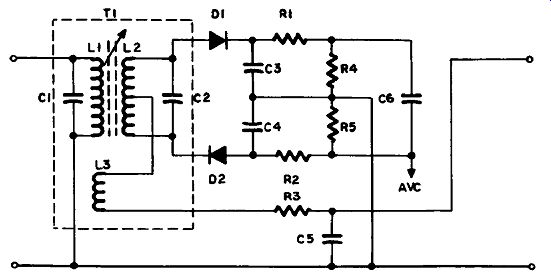
Figure 1.1 Typical Circuit Schematic (Pats Values Omitted)
Active and Passive Elements
Circuit elements are either active or passive. Passive elements are those which do not require an external source of power in order to function. They include resistors, capacitors, inductors and the like.
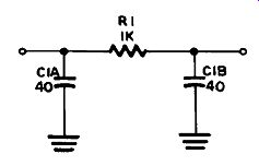
Figure 1.2 Pi Filter (Parts Values Included)
DC POWER LOW SIDE. ZERO POTENTIAL, GROUND RETURN
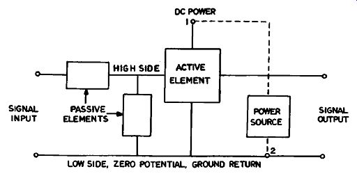
Figure 1.3 Circuit Conventions
Active elements are vacuum tubes, transistors and other devices that use external power, which they introduce into the circuit to modify an existing signal or to generate a new one. In this guide diodes are classified as active elements also, although in many respects they seem to be more like passive elements.
External Power
When an active element is included in a circuit the external power is generally shown as entering and leaving in a vertical direction, perpendicular to the signal low. Since this power is direct current (DC) its path is also characterized by the absence of capacitors (which block DC).
In Figure 1.3 the power source is drawn as if it were part of the individual circuit, but the dashed lines indicate that this is not usually the case. In the overall schematic of a complex piece of electronic equipment, such as a television set, where many circuits share one power source, the power supply would be shown separately, and the external connections to it (1 and 2 in Figure 1.3) might even be omitted.
Circuit Identification
The majority of circuits consist of a small number of passive elements built around an active element. The type of active element gives you your first hint as to the nature of the circuit. A tube or transistor has a type number, apart from the reference number, and if you look it up in a tube or transistor manual you'll often see what type of circuit it is likely to be used in. Some tubes, for instance, are only used in certain types of circuit. A 12BE6, which is a pentagrid converter, is only used in a converter circuit , so you know what type of circuit it is without looking further. But this is like looking up words in the dictionary.
The purpose of this guide is to show you how to read schematics with out having to look things up.
Circuit-Finder Table
Until you have had some practice, however, it will help to use Table II as a guide in identifying circuits. This table is provided to steer you to the right part of the guide, where you'll find specimen circuit dia grams and descriptions which you can compare with the circuit you're interested in to confirm your identification and find out how it works, and how to diagnose troubles in it if necessary.
How to Use the Circuit Finder
Examine your circuit, and ask yourself the following questions:
(1) Is the active element a vacuum tube or semiconductor? (2 ) Is it a diode, or other type? ( 3) Is it single, paired, or in a set of four? (4) What principal passive elements or special connections are associated with it? Then find in the first four columns of Table II the right combination of answers to these questions. In the column at the right you'll see where to look in the guide for further details. For example, sup pose you , re looking at the circuit shown in Figure 1.1. The first thing you notice is that there are two semiconductor diodes in the circuit.
Then you1ll note the center-tapped transformer at the left, with another winding connected to the centertap. In Table II look down the semi conductor column until you come to Diodes (2). Then look in the Significant Passive Elements column, where you’ll find your transformer listed opposite Diodes (2). In the right-hand column you’re told the circuit is an FM Demod. When you turn to the reference given in the last column you find it can be either a Discriminator or a Ratio Detector, depending upon which way the diodes are facing. These are facing in opposite directions, so its a Ratio Detector.
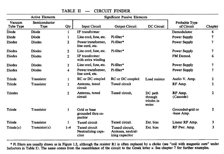
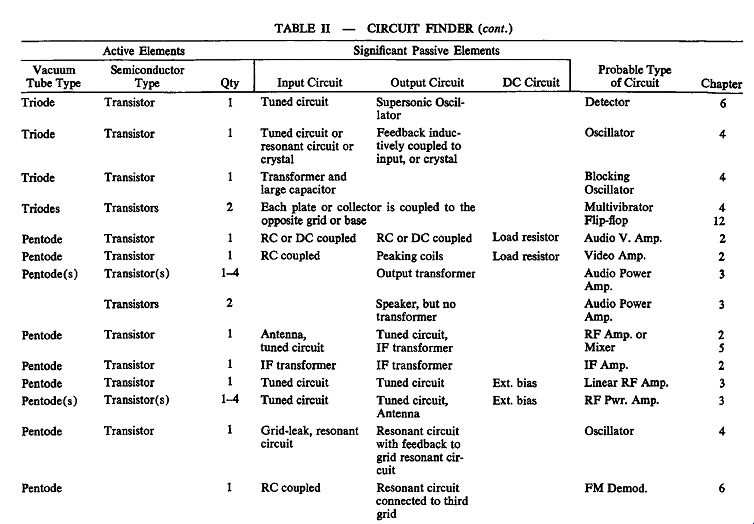
TABLE II