35. Harmonic and Overtone Operation
The use of the terms "harmonic" and "overtone" often leads to confusion because, as nearly synonymous as these expressions may be, their connotations are often vastly different. Since both terms refer to multiples of fundamental frequencies, it is advisable to distinguish between them as they are to be applied in this Section.
Harmonic operation of a crystal oscillator occurs in a circuit in which the crystal vibrates in its fundamental mode. Harmonics of the fundamental frequency are obtained by tuning-usually in the output circuit-to multiples of the crystal frequency.
Overtone operation occurs in a crystal that oscillates in one of its overtone modes rather than at its fundamental frequency.
Harmonic output from such oscillators is realized by amplifying the crystal's overtone oscillation directly. There is no fundamental frequency signal present in such an oscillator.
For a great many years, crystal control at frequencies above 20 me could be accomplished only by utilizing one or more cascaded frequency multipliers, with the attendant problems of removing unwanted harmonic frequency components. The first steps toward the elimination of the problem came in the form of harmonic oscillator circuits such as the famous tri-tet crystal oscillator; later, other electron-coupled harmonic oscillators made their appearance on the scene and their use became quite common.
The introduction of overtone crystals, however, marks the inception of very high frequency crystal control. For example, a crystal-controlled amateur transmitter on 144 me might use a crystal marked "24 mHz"; the output of the crystal oscillator might then be doubled to 48 mHz, then tripled to 144 mHz and used to drive a high power 144- mHz final class C amplifier. Such a 24- mHz crystal is really an 8- mHz AT cut specially "treated" for overtone characteristics so that it oscillates freely on its third harmonic mode.
It should be pointed out that the frequency of a crystal's oscillation at an overtone mode may not be an exact multiple of the frequency of the same crystal's oscillation at its fundamental frequency. The physical "breakup" of the crystal for overtone vibration is not always into exactly equal parts. Accordingly, a crystal accurately ground for a fundamental frequency cannot be expected to be accurately ground for an overtone frequency. Crystals to be operated on overtone frequency should be ground by the manufacturer for the overtone to be used, and the overtone frequency specified. These crystals may also be used on their fundamental frequency, but this fundamental frequency will not usually be exactly the overtone frequency divided by a whole number.
The paragraphs immediately following deal with harmonic oscillators of the tri-tet type; those toward the close of the Section are concerned with overtone operation.
36. Fundamental Tri-Tet Circuitry
The name "tri-tet," derived from triode-tetrode, implies that the oscillator tube behaves as a triode (screen acting as oscillator plate) and as a tetrode (plate acting as output electrode) simultaneously. Since many of the circuits previously discussed also follow this pattern, a further qualification must be added to differentiate these from the conventional tri-tet. The tri-tet designation is used to describe oscillator circuits in which the output plate tank is in series with the oscillatory tank, with the tube between the two (Fig. 30). The L1-C1 combination may be visualized as the generator of r-f energy, because it is the oscillatory tank. The cathode to-plate path within the tube and the output tank L2C2 are all in series with it as shown in Fig. 30 (B) .
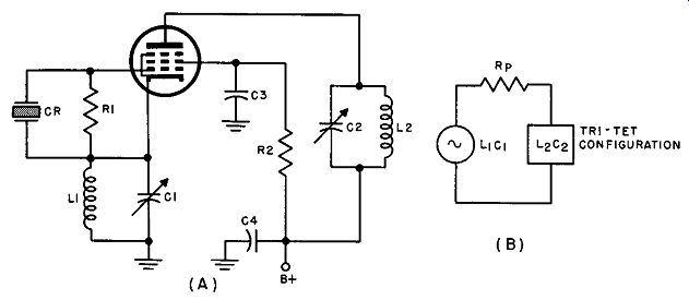
Fig. 30. (A) Tri-tet circuit, (8) tri-tet equivalent circuit.
In use, the oscillatory tank circuit (L1C1) is tuned to a higher frequency than that of the crystal, while the output circuit is resonated to the multiple of the fundamental-the second, third, and sometimes fourth harmonic. Excitation to the crystal is governed by the characteristics of the LJCJ pair; poor design and adjustment of the cathode circuit components are often responsible for inadequate performance of the tri-tet and should be given careful attention if optimum operation is desired.
The cathode tank circuit should be designed to have a low L/C ratio and to be inductive at the crystal frequency; this means that L1C1 should be tuned to a frequency that is decidedly higher than that of the crystal-approximately 1-½ times higher at fundamental frequencies in the region of 2 to 8 mHz, for example. This design enables the cathode tank to bypass much of the fundamental energy, thus preventing excessive excitation and high crystal current.
The principal advantage of the tri-tet circuit over other electron-coupled frequency-multiplying oscillators is that the excitation voltage tends to increase with an increase in load. If the output is inductively coupled to the succeeding stage, the tri-tet arrangement tends to stabilize the output level when the amount of coupling is varied. This effect is entirely due to the fact that the excitation control circuit (L1C1) is in series with the output circuit as previously explained, and an increase in circuit loading must result in a rise of energy dissipation in the excitation tank with a concomitant increase in crystal excitation.
Tri-tet frequency stability is measurably lower than that of conventional pentode circuits because of the large stray capacitance that directly shunts the crystal unit. The stray capacitance comes to about 8 µ.µ.f in the average circuit. About 4 µ.µ.f of this is due to the capacitance between the control grid and the screen grid and another 4 µ.µ.f is due to the capacitance of the grid leads to ground, which otherwise would be part of Cu.
As in other harmonic generators, high harmonic output is obtainable only when the plate current is cut off for a large part of the cycle, making for greater distortion and richer harmonic content. If the frequency is being doubled, plate current should flow for about ¼ of the time; if it is being tripled, plate current should flow for approximately 1/6 of the time. To generalize, if the frequency is to be multiplied n times, optimum nth harmonic output is approached if the oscillator is designed so that the tube conducts for approximately ½ n of each fundamental cycle.
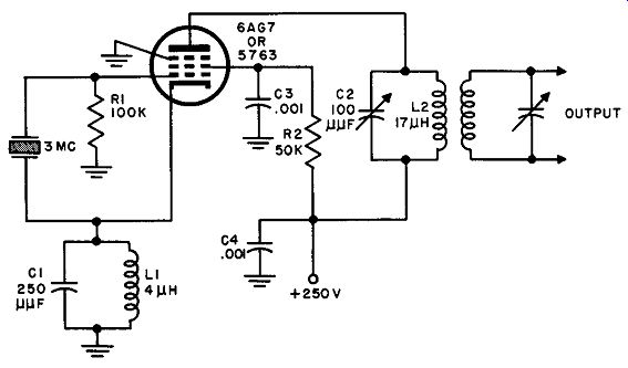
Fig. 31. Miller tri-tet oscillator.
37. A Practical Miller Tri-Jet Oscillator
The circuit pictured in Fig. 31 was designed for use with a crystal on or about 3.0 mHz. It is essentially the same as the basic circuit in Fig. 30, differing only in a few details.
A tube such as the 6AG 7 is recommended for a circuit of this type because of its good internal screening, although other tubes having similar characteristics can be made to perform satisfactorily.
Grid resistor R1 is, in this case, returned to ground rather than to the cathode for a more convenient wiring layout; it should be noted, too, that the suppressor grid in the 6AG 7 or 5763 is externally connected to ground rather than to cathode, and that the cathode tank circuit has a low L/C ratio as called for by proper design.
Such an oscillator is suitable for use as the crystal driver for a multi-stage transmitter, as a calibration oscillator, or in any application where strong, stable harmonic output is desired.
38. A Practical Pierce Tri-Tet Oscillator
The type of oscillator with which one is dealing is not always evident from a cursory inspection of the schematic diagram. For those who are interested in naming the circuit under study-and this is often very difficult because of the multitude of modifications that may be made in the fundamental design-a rule that is usually (though not always) safe for differentiating between Pierce and Miller circuits is this: if one end of the crystal is at the same radio frequency potential as the plate (or screen in electron-coupled oscillators) the circuit is probably a Pierce; if one end of the crystal is at the same radio-frequency potential as the cathode, it is probably a Miller Oscillator.
This point is made here because a casual glance at the circuit of Fig. 32 would seem to give the impression that it is a Miller modification until one recognizes that the bottom of the crystal does not return to cathode potential. In the circuit given in this figure, excitation is controlled by means of C1; the cathode tank circuit consists of the r-f choke and C1; the bottom of the crystal is returned to the screen (making it a Pierce circuit. as explained previously) though C4; and the plate tank circuit is tuned to the second harmonic of the crystal frequency. This Pierce tri-tet oscillator is used as a crystal calibrator in Frequency Meter TS-186/UP. and is furnished with a 5- mHz crystal.
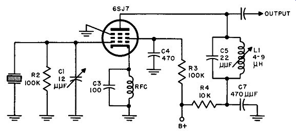
Fig. 32. Pierce tri-tet oscillator circuit.
39. Series-Mode Oscillation
In general, crystals show definite response characteristics at two distinct frequencies; the series resonant frequency (f ,) and the anti resonant frequency (fa) as described in Par. l O and illustrated in Fig. 7. All of the oscillators discussed thus far are typical of parallel resonant circuits for which the operating frequency lies somewhere between fr and fa.
This requires further clarification.
Although an oscillator may depend upon a crystal operating at its series-resonant frequency (/,) as will be shown in subsequent paragraphs, it is not practicable for a crystal unit to control an oscillator at the anti-resonant frequency (fa). Although it would seem that the conditions for parallel resonance are best met at the anti resonant frequency of the crystal, because it is at this point that the impedance of the crystal unit is maximum and is thus extremely sensitive to frequency changes, consideration of the circuit as a whole shows at once that such an assumption is incorrect. The input of the vacuum tube shunts the crystal unit; this shunt circuit has a much lower impedance than that of the crystal at anti-resonance so that the total impedance will be relatively insensitive to small frequency variations in the region of fa.
In practice, the actual frequency of Pierce, Miller, and other parallel-resonant crystal oscillators lies between f, and fa to take ad vantage of the steep slope between these two frequencies (Fig. 7) . In this region the crystal unit is still very sensitive to small frequency changes, but its impedance is much lower than at anti resonance, hence the effect of the shunt circuit is not as severe.
With the introduction of overtone crystals,, series-mode operation (operation at series resonance) becomes more widely used be cause of its excellent frequency stability characteristics. At series resonance, the crystal element appears as a very small resistance, so that in the normal circuit it can be short-circuited or replaced by a comparable resistance without stopping oscillations. Quite often, satisfactory control is obtained simply be designing a conventional variable-tuned oscillator to operate at the desired frequency, and then inserting the crystal unit in a plate tank or feedback circuit.
Over a very definite range of adjustments, the crystal can assume control and hold the frequency nearly constant. However, a number of special oscillator circuits have been designed specifically for series-mode operation and, most often in new equipment planning, one of these is utilized if overtone operation is contemplated.
Although the scope of this guide does not permit discussion of all the various types of series-mode oscillator, the recommended de signs are given below for future reference or most extensive reading: Meacham Bridge, Capacitance Bridge, Butler, Grounded Cathode, Grounded Grid, Grounded Plate, Transitron, Impedance-Inverting Pierce and Miller, Two-Stage Feedback, and Modified Colpitts.
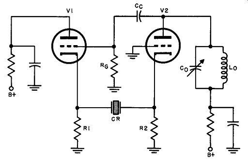
Fig. 33. Basic Butler type overtone oscillator circuit.
40. The Butler Oscillator
At the time of writing, probably the most widely used of the series-mode oscillators is the Butler cathode-coupled two-stage oscillator. Its popularity is attributable to its simplicity, versatility, frequency stability, and reliability. Especially with older overtone crystals, it was generally found that the Butler circuit was least critical to design and to adjust for operation of the crystal at a given harmonic. The balanced arrangement of the circuit and the fact that twin triodes are common and inexpensive contribute to the economy of its construction and to short lead design.
The basic Butler oscillator is illustrated in Fig. 33. V1 is a cathode follower, which is coupled to the grounded-grid amplifier, V2, through the crystal unit. The resonant circuit, C0 L0 , is tuned to the desired overtone of the crystal and, when power is applied, produces a transient oscillation, which is applied as a voltage to the grid of V1. At series resonance, the resistance of the crystal is low, so that the voltage drop across R1 due to the coupled oscillation is fed back with little loss to the cathode of V2, thus maintaining oscillation. At any frequency other than that of the overtone of the series-resonant frequency, the crystal presents a high impedance to the flow of feedback current (See Fig. 7) preventing the loop from compensating for circuit losses. Thus, when oscillation does occur it is at the frequency of the crystal overtone and no other.
Should the crystal be shorted out, the crystal would still oscillate at a frequency governed by the values of C0 and L0 because in this circuit, the crystal behaves as a series resistance of very low value. The control value of the crystal lies, of course, in the fact that it has this low resistance only at its series resonant frequencies, and therefore permits sustained oscillations only at fr or its over tones.
41. Design Considerations for Butler Overtone Oscillators
If an oscillator is to operate below 20 mHz, the Butler circuit has little advantage over the simpler Pierce or Miller. At the higher frequencies, however, it will be found that the Butler oscillator has the advantage of ease of adjustment and dependability.
In selecting the vacuum tube, space and weight considerations suggest the use of a twin-triode or twin-pentode unless a more balanced arrangement is possible with separate tubes. The trans-conductances of V1 and V2 should be as high as possible for maximum frequency stability.
If the oscillator is to operate in Class A, both tubes may be of the same type; for Class C operation, however, the power rating of the cathode follower should be greater than that of the grounded grid amplifier, a condition that usually requires the use of separate tubes. If it is desirable to isolate the load from the oscillator, a pentode may be used in an electron-coupled circuit for V1 (Fig. 34), with the screen serving as the plate of the oscillator.
In the vhf range triodes may be preferable because of their smaller transit-time effects. To reduce transit time to a minimum, the plate voltages should be as high as practicable; in addition, the use of high plate voltage raises the transconductance and hence the stability of the system.
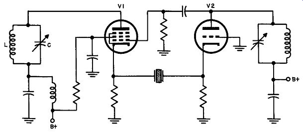
Fig. 34. Electron-coupled Butler oscillator circuit.
The electron-coupled circuit of Fig. 34 is similar to that of the basic Butler circuit except for the presence of the second tuned circuit, LC. The screen of V1 is the plate of the oscillator while the output is taken from the plate of the tube. LC is tuned to the desired crystal overtone but has little loading effect, and consequently helps maintain the frequency constant even when the load varies within limits.
42. Capacitance-Bridge Series-Mode Crystal Oscillator
A bridge of any kind is essentially an arrangement in which a balanced condition is established through proper choice of resistive, capacitive, and inductive components. In the bridge circuit of Fig. 35, meter M reads zero when the bridge is in balance, because the potentials at points A and B are the same, equal voltage drops having occurred across the bridge arm components. Under these conditions, the component relationship is:
C2/C1=L1/L2.
Consider now the effect of substituting a crystal unit for C2. At a frequency removed from the series-resonant frequency, the crystal unit simply behaves as a capacitor; hence the conditions are essentially identical to those which obtain if this arm contains an ordinary capacitor except at the resonant frequency. When f, is reached, the crystal unit becomes purely resistive, thus completely upsetting the bridge balance. Thus, a bridge of this variety may be balanced for all frequencies above and below the crystal frequency (within rather wide limits) by means of a single adjustment, but at the crystal frequency it will be unbalanced.
By adding another capacitor as shown in Fig. 36 (A) the bridge may be used as a tank circuit without affecting its balancing function. Figure 36 (B) illustrates the same arrangement redrawn to clarify the designation of tank circuit. C3 is now the tuning capacitor, while C1 retains its ability to balance the bridge.
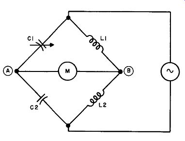
Fig. 35. Basic capacitance bridge circuit.
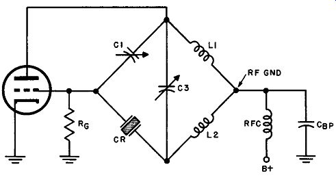
Fig. 37. Basic capacitance bridge oscillator circuit.
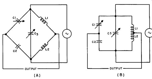
Fig. 36. (A) Capacitance bridge circuit and (B) its form as a tank circuit.
Figure 37 is a drawing of this bridge circuit connected to form a crystal-controlled oscillator. L1 and L2, in this case, are actually a single, tapped inductance with the two sides wound on the same form and tightly coupled together. The induced-voltage effect is equivalent to that of a single generator connected across both coils (as in Figs. 35 and 36) and driving the bridge with an emf that is roughly equal to the voltage across L1 multiplied by the turns ratio plus one. That is, driving emf = El (T. R. + I). The turns ratio is usually and most conveniently made equal to 1 so that the inductance may be center-tapped.
As long as the bridge is in balance as a result of prior adjustment, oscillation cannot take place, because the voltage applied be-tween grid and ground must be zero. Therefore, before the oscillator is put to work, the bridge is balanced with C1, using a signal from an external generator of some frequency either above or be low the crystal fr. For this balancing adjustment, the capacitance of C1 is reduced to minimum, then C1 is slowly meshed and, at some point, oscillations suddenly start. This is the point where fr has been closely approached, so that the crystal behaves as a resistor in stead of a capacitor, throwing the bridge off balance. When this occurs, voltage appears between grid and ground at the crystal frequency and the circuit is then capable of sustaining oscillations. As in other series-mode oscillators, the frequency to which the tank circuit is tuned may be that of one of the crystal overtones or that particular overtone specified by the manufacturer on the crystal unit.
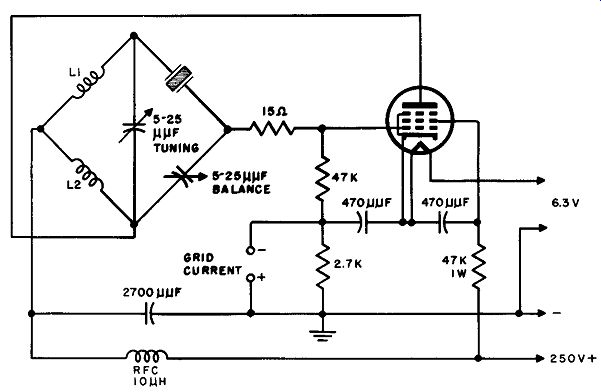
Fig. 38. Capacitance bridge oscillator circuit particularly designed for use
In the 50-90 mHz frequency range.
43. A 50- to 90- MHz Capacitance Bridge Oscillator
The capacitance-bridge oscillator shown in Fig. 38 has been operated at frequencies as high as 135 mHz but its particular merit lies in its performance at frequencies between 50 mHz and 90 mHz.
Values for all the components except L1 and L2 are given in the schematic diagram; the coils are made up of a single center-tapped inductance whose magnitude must be determined by calculation for a particular crystal unit. Provision is made for measuring grid current to determine optimum operating adjustments. R1 is inserted to prevent momentary crystal overdrive during the tuning process. In all other respects, the circuit functions as described in the preceding paragraph.
44. Other Series-Mode Oscillators
Space prohibits an extended discussion of the other kinds of series-mode oscillators mentioned in Par. 35. It is felt, however, that the reader may be interested in a tabular comparison of these with respect to specific features. Table 3 is a condensation of authoritative research information of recent years compiled by the United States Department of Commerce. It should be realized that the ratings for the different oscillators are based on average qualitative results reported by qualified investigators but that any rating may vary in individual cases.
45. QUIZ
1. Distinguish between the terms "harmonic operation" and "overtone operation."
2. Draw the circuit of a fundamental tri-tet oscillator.
What does the name tri-tet refer to?
3. Explain the circuit operation and the principal advantages of the tri-tet crystal oscillator.
4. Sketch a practical Miller tri-tet oscillator employing a 6AG7 tube. Compare your drawing with Fig. 31 and explain the function of rid resistor R1.
5. How does Fig. 32 differ from the circuit of question 4?
6. Explain the operation of the crystal element in series-mode oscillation at the resonant frequency.
7. Draw the circuit of the Butler cathode-coupled two-stage oscillator.
8. Explain the circuit operation of the Butler oscillator.
9. Refer to Fig. 37, and explain the operation of the capacitance-bridge series mode oscillator.
10. In what respects do the circuits of Figs. 37 and 38 differ?
TABLE 3 RATINGS : FOR SERIES-MODE OSCILLATORS
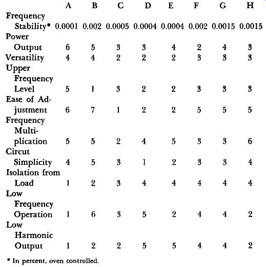
A-Meacham Bridge :F-Impedance Inverting B-Capacitance Bridge Miller C-Butler G-Impedance Inverting D-Grounded Grid, Pierce Transformer Coupled H-Modified Colpitts E-Transition (1 is highest rating, 7 is lowest rating)