AMAZON multi-meters discounts AMAZON oscilloscope discounts
<< cont from part 1
TYPES OF DIAGRAMS
Two basic types of diagrams are encountered frequently in control circuit drawings: (1) the one-line diagram, and (2) the ladder diagram. The one-line diagram includes everything in a single line, which is read from the top to the bottom. The one-line diagram is most often used in power distribution drawings. It represents one phase of a three-phase system (where each phase is identical), which if all three were drawn would represent the entire distribution system. The reference to one line means that an entire function can be described in one line from the power source to ground. For motor-control circuits the ladder diagram is most often used. The diagram itself looks somewhat like a ladder, with two long vertical lines representing the primary power source and all the components connected horizontally (like rungs) between the power lines.
The primary difference then is the application of distribution or control functions. As can be expected, one-line diagrams can be found most often in utility or power companies to represent their distribution systems across the country. These are discussed more fully in Section 17. Ladder diagrams are used in industries that need some control functions performed by switches, relay coils, and motors.
Ladder Diagrams
Ladder diagrams consist primarily of motor-control circuits and include all the circuitry necessary to energize or de-energize these motors. The ladder diagram, like other circuit diagrams, is prepared so that it can be read from the upper left-hand corner, across to the right, and down the page. The diagram is constructed so that the main power lines are drawn as vertical lines down either side of the diagram. All circuit functions are drawn on horizontal lines connected between the two main lines. Frequently, control functions are produced sequentially, and the horizontal lines indicate the sequence.
The control circuit consists of two basic parts: the actual motor circuit, or power portion, and the control portion. The use of the term ladder diagram stems from the layout of the control portion of the circuit. FIG. 22 illustrates that an easy visual distinction could be made between the two portions of the control circuit if the motor portion were prepared with a dark, medium to heavyweight line and the control portion were prepared with a light, thin-weight line.
Spacing requirements for the layout of ladder diagrams are determined by the amount of lettering that must be included between the horizontal lines. There should be sufficient room to ensure that the lettering will not run into the linework even after reductions. Keep in mind that when a drawing is reduced the overall size is reduced, but the line width and the space between the lines are also reduced. A drawing that may seem comfortable to read on a large (D size) print may be come impossible to read after it is reduced. Most lettering on diagrams should be from 1/8 to ¼ in. through out. Thus, the space between the horizontal rows on a ladder diagram should be no smaller than 1/2 to ¾ in., which will ensure that the lettering can be included without confusion.
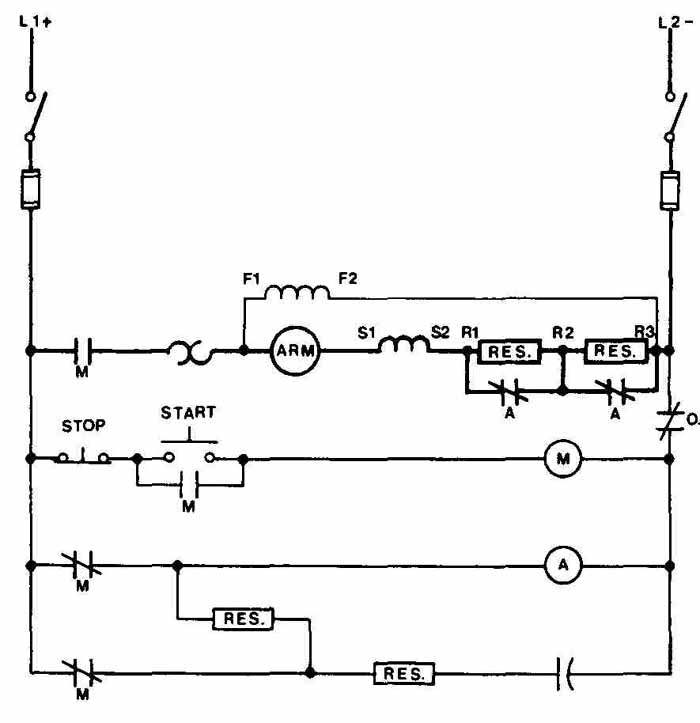
FIG. 22 Control circuit showing heavy, dark lines for the motor portion
and light, thin lines for the control portion.
The length of the vertical main power lines is determined by the number of horizontal lines needed for the control portion of the circuit. The width between the vertical power lines is determined by the horizontal line that contains the largest number of devices. Once that line has been located, it is used to help lay out the rest of the circuit. It is not uncommon for the control portion of the circuit to be a different width than the motor portion. One of the most obvious reasons is shown in FIG. 23, where the stop button needs to de-energize all the coils at the same time. The only way to be certain that this will be done is to make all the control lines connect to the side of the stop button that will place the button between the coils and the main power line.
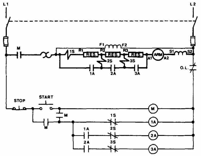
FIG. 23 A single stop button to de-energize all coils at the same time.
As for all other circuits, it is highly desirable to present a well-balanced and carefully laid out diagram. When placing the devices and components on each horizontal line, be sure that they maintain some form of alignment. For example, many times a lengthy control circuit contains several rows of sequential circuit functions with a pair of contacts and a coil. All the pairs of contacts should be aligned vertically, and the centerlines for the circles used to represent coils should also be aligned vertically, as shown in FIG. 24.
These coils and pairs of contacts may not line up with the main contactor and pairs of contacts in the first line of the control circuit. Generally, this line contains more devices than the other lines because it usually includes the start and stop switches and overload devices that other coils do not need. When this is the case, the first line should be well balanced and nicely spaced. Equal distance between each device gives a well-balanced drawing. This may be a little difficult to achieve without some practice. The width of each device is different and has to be taken into account when the overall spacing is determined.

FIG. 24 Vertical alignment for coils and contacts.

FIG. 25 Different devices maintaining consistent size relative to each
other: circles, ½ to % in.; contacts, ¼-in, lines, 3 in. apart; overall
switch length, 1/2 in.; and resistor rectangle, 3 X ¾ in.
As shown in FIG. 25, a good size for the circles is ½ to ¾ in. diameter, which leaves enough room to add the letter or reference inside the circle. The pairs of contacts should be drawn with ¼-in, parallel lines located approximately /16 in. apart. All the other devices should be drawn relative to these sizes. For example, the switches should be about ½ in. overall, with the rectangles for the resistors drawn about /16 by ¾ in., which allows for ½-in, lettering to be included within the rectangle.
DC CONTROL CIRCUITS
Control circuits must provide a number of control functions pertaining to the operation of the motor. The type of function is determined by the actual use of the motor. For example, the control functions of a motor used in an elevator are much different from the control functions of a motor used in a heating system. In both instances, however, the primary functions of starting, stopping, running, speed control, and protection all have to be considered. The simplest circuit may include only a two- position switch for the starting and stopping and a single speed and direction for the running portion, as shown in FIG. 26. There should be some type of circuit protection, such as overloads, on even this simple a circuit. The other extreme can include time delays, levels of speed control, forward and reverse functions, and automatic starting, as shown in FIG. 27.
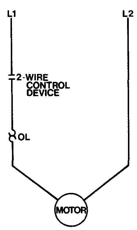
FIG. 26 Very simple motor circuit with manual ON/OFF control and single
operating speed.
The main power lines for the DC control circuit are shown as positive and negative. As a general rule, the vertical line on the left is used as the positive, which allows conventional current to flow from left to right across the diagram. If any switches, circuit breakers, or fuses are needed for the main power lines, they should be drawn very near the top of the diagram. In preparing the location of all the circuit devices to be placed on the horizontal lines between the main power lines, keep in mind that switches, contacts, resistors, or other similar devices and components are placed on the line so that they are encountered first. The motor starters or relay coils are located toward the right or at the end of that line toward the negative power line, as shown in FIG. 28. When resistors are used in the control circuits, the reference designation and value of the resistor are normally lettered within the rectangle used to represent the resistor. Designations for the relay coils and other contactors are also lettered within the symbols used to represent these devices.
The connecting lines used in control circuits must follow the conventions for crossovers and junctions. The method of using a dot for a connection and no dot for a crossover, as shown in FIG. 29, is almost always used. The dot is used to indicate that an electrical connection exists between the two wires that are crossed. When a crossover is drawn and no dot appears, it simply means that the lines pass by each other and do not make any electrical connections. As on all other diagrams, crossovers and changes of direction should be kept to an absolute minimum. So that it is easier to follow circuit paths and to document the control circuit, the horizontal lines are given a number. All horizontal lines should be numbered even if they do not extend across the entire diagram from one main power line to the other, as in FIG. 30.
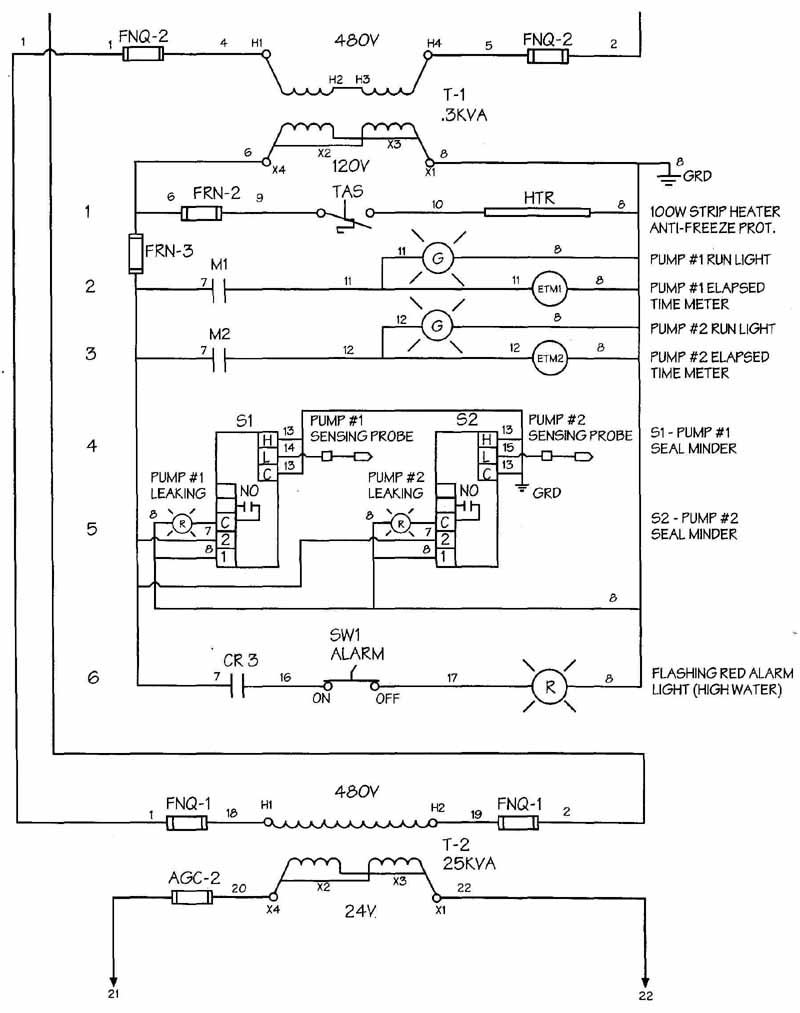
FIG. 27 Portion of a larger, more complex control system.

FIG. 28 Contact located toward the left side of the control line and
coils situated closer to the right side.
DC Motor Circuits
For the DC control circuit diagrams, the motor portion is included as additional horizontal lines connected between the two primary or main power lines. The line includes two sets of main contacts, with one on each end of the line, the armature of the motor, any starting resistors or other means of direct motor control, and all the necessary overloads. The motor circuit portion normally contains two lines, an armature, and a field line that includes the field coil, a vari able resistor, and a field loss coil, which keeps the motor from running extremely fast if the field be comes open.
In FIG. 31, the vertical lines represent 250V DC. Both the motor circuit and the control functions are shown on the diagram. Notice that only the lines of the control portion of this circuit are numbered. The first device is a main disconnect switch to remove all power from the circuit. Both lines, positive and negative, contain the disconnect switches and a fuse to provide over load protection. The first horizontal line includes the armature portion of the motor. In this circuit, speed control is provided and is represented by the rectangle for the resistor and contacts connected at intermediate points. Notice that this line includes the contacts for the motor starter (M). There are two sets—one on each end of the line. The second line also contains a portion of the motor circuit, frequently referred to as the field circuit because it represents the field portion of the motor. This line includes the field windings, the field rheostat, and the field loss relay for protection. Lines 1 through 5 contain the motor control circuit. The control portion of the circuit includes all necessary devices to provide control functions, such as starting and stopping and, in this case, speed control of the motor. Speed control is provided by the resistor in the armature circuit.

FIG. 29 Connections indicated with a dot. (When wires simply cross over,
there is no dot, indicating no connection.)
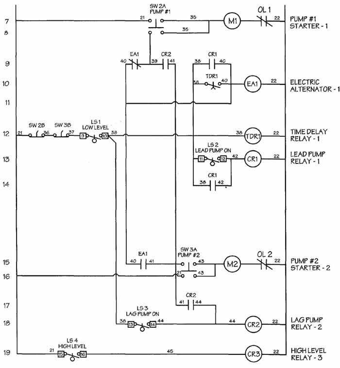
FIG. 30 Control lines numbered on the left hand side for ease in tracing
circuit functions.
AC Motors and Control Circuits
The primary difference between AC and DC motor control circuits is in the motor itself. Either motor can be controlled by a DC control system. The difference is that the AC motor itself needs to be connected to an
AC power supply, either single phase or multiple phase. Typically, an AC motor operates on a three-phase system, which is fairly easy to produce.
For this type of diagram it is not uncommon for the motor circuit to be arranged horizontally and the control circuit to be arranged vertically. FIG. 32 shows a typical motor control circuit, which includes both an AC control circuit and AC motor circuit. Notice the dark, heavyweight lines used to identify the motor portion of the circuit. The three lines are identified as L1, L2, and L3. They indicate the main power supply, which should be three-phase power. Shown connected directly 2FU to the rotor windings are the resistors and contacts used in the speed control of the motor circuit. The control circuit itself is connected between L1 and L2. Sometimes the main power supply is too large to be safe for the control operations or personnel, and a transformer is connected between the main power lines and the control portion of the circuit, as shown in FIG. 33.
The motor portion of the circuit is not always represented with the horizontal orientation. It is just as commonly presented with the power lines as vertical lines and the control portion drawn to one side or the other, as in FIG. 34.
The use of widely accepted standards has been suggested frequently in this text. The Joint Industrial Council (JIC) publishes standards for control circuits and, as mentioned in earlier Sections, the use of these standards by industry is strictly voluntary. Most companies, however, find it convenient to use these widely accepted standards in the preparation of all in-house material, as well as for materials produced for publication.
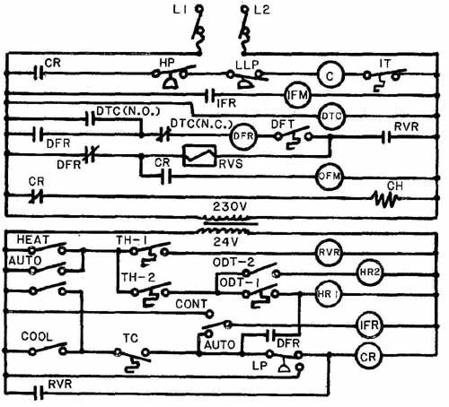
The elementary or ladder diagram shown in FIG. 35 is used to demonstrate drawings conforming to JIC standards. The motor circuit is included at the top of the page and is oriented horizontally with a three- phase main power supply. The control circuit portion is connected between two of these lines and is oriented vertically. Notice that this circuit includes two motors, not just one. These two motors are connected to be started with the same set of main contacts. This particular circuit contains many different types of control functions. Although this circuit is meant only to demonstrate good layout techniques, it is important to note that a more complex control circuit may be very similar to this.
The control portion of the circuit is connected by way of a transformer to step the voltage down to suitable levels. Each line shows excellent spacing and vertical alignment. All the control relays are in line vertically and are located nearest the right-hand power line. Each line in the control circuit is assigned a line number, which is used simply for reference and identification. Line numbers are found on the left-hand side of the drawing. On the right side, for more complex circuits a short description of circuit function is frequently included. In addition to the actual circuit and the notes on the circuit, it is necessary to include documentation that describes the sequence of operation. This sequence should be a complete description of how the circuit operates. It is often included on the same drawing as the ladder diagram.
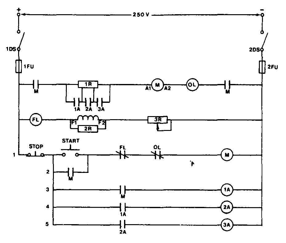
FIG. 31 DC control circuit and motor circuit.

FIG. 32 AC motor using AC control with push-button speed selection.
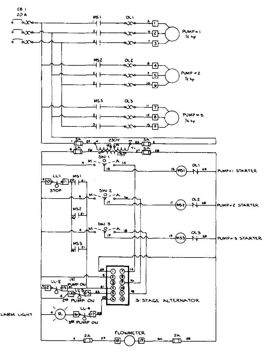
FIG. 33 Transformer used to step down voltage for control portion.
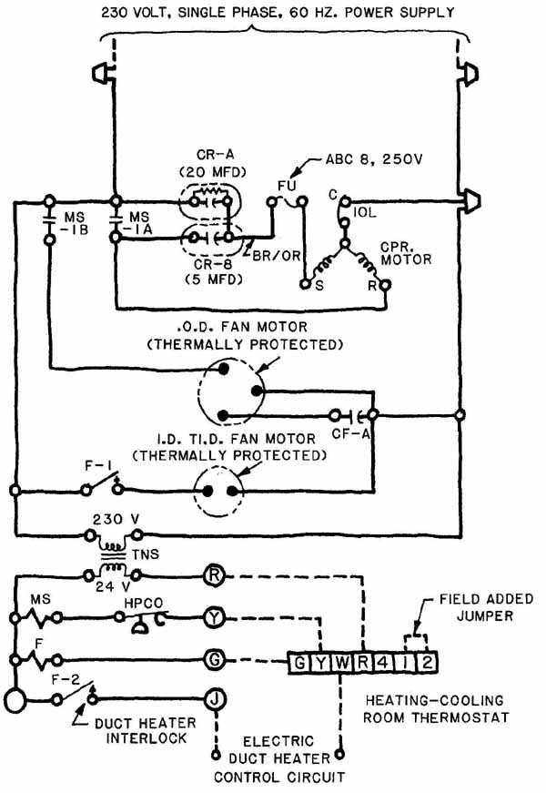
In addition to the ladder diagram that describes the circuit function or operation, a wiring diagram is prepared that actually demonstrates how the control circuit should be wired. Wiring diagrams were covered extensively in Section 13. One type of drawing discussed was the point-to-point wiring diagram. Most wiring diagrams for control circuits using electromechanical control are the point-to-point type of diagrams.
The primary difference between the control circuit diagram and the wiring diagram is in the layout. The control circuit is a functional representation and is laid out for the most convenient visual recognition of the circuit functions. The wiring diagram is most concerned with a quick visual recognition of the actual wiring layout. As illustrated in FIG. 36, this diagram is frequently prepared to show the physical relationship between devices and connecting wires. This wiring diagram could be the physical representation for the circuit shown in FIG. 34.
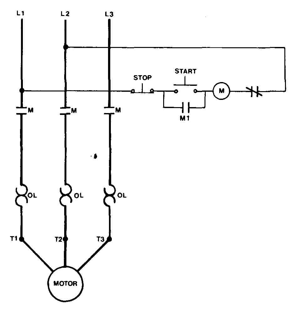
FIG. 34 Vertical orientation for main power lines to motor with control
portion located off to one side.
USE OF CAD
As in all other types of drawings, it is possible to use a CAD system to aid in the preparation of control circuit diagrams. FIG. 37 shows the typical electrical symbols as they were generated by a CAD system. These symbols can be in the library of parts and can be placed anywhere on the circuit diagram with the use of a light pen or digitizer tablet. It is the ultimate responsibility of the drafter to maintain company standards in all drawings or diagrams that are prepared.
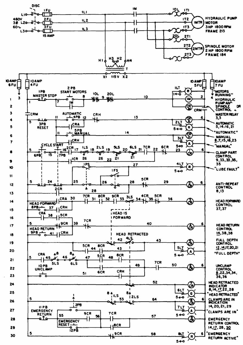
FIG. 35 Ungrounded control circuit. (Joint Industrial Council)
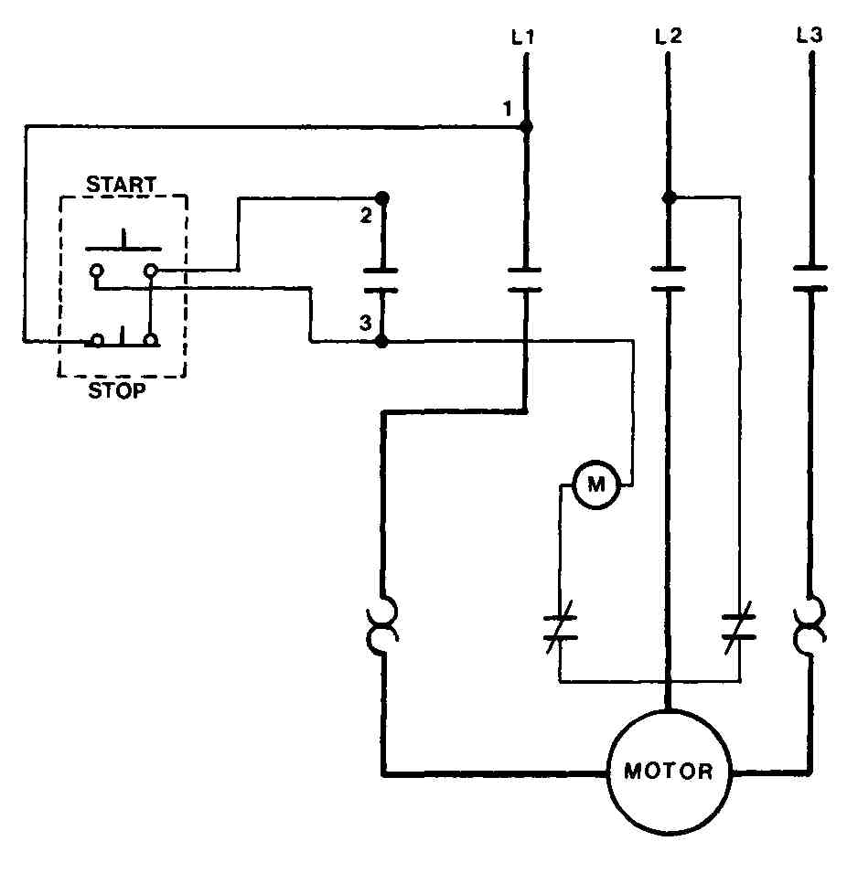
FIG. 36 Typical wiring diagram showing physical characteristics and
placement.
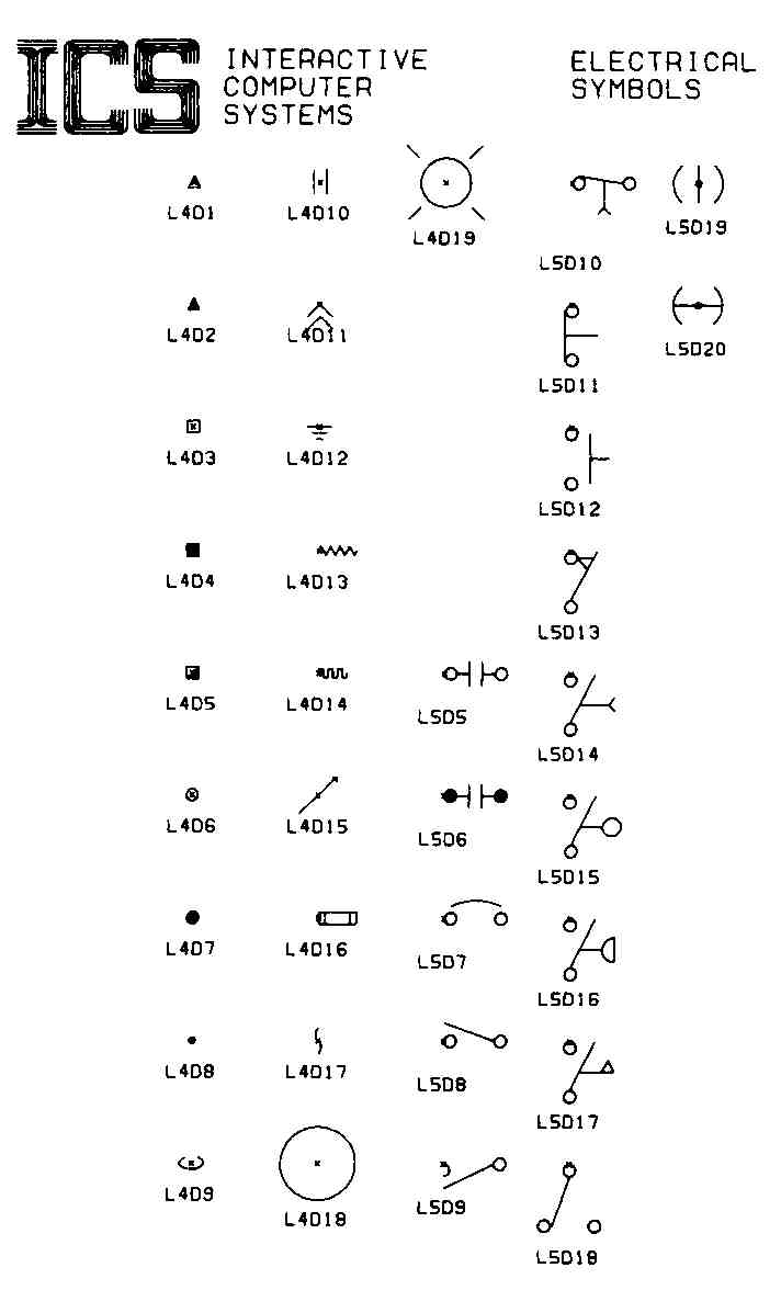
FIG. 37 Electrical symbols generated by a CAD system. (Interactive Computer
Systems, Inc.)
REVIEW QUESTIONS
1. List the basic types of drawings found in control circuits.
2. Why does a one-line diagram or single-line diagram usually have more than one line?
3. Do control circuit symbols conform to the same standards as symbols used in schematics diagrams?
4. How are the motor portions and control portions represented differently on drawings?
5. Using Appendix F, determine the meaning of the following reference designations:
a. CB
b. F
c. LS
d. O
e. R
f. TB
g. T/C
6. What two basic circuits are needed to draw a motor control circuit?
7. How are contacts drawn on the circuit, in their energized or de-energized states?
8. Why are horizontal lines in the control circuit numbered?
9. What must be done if the control circuit needs less voltage than the motor circuit?
10. Why are CAD systems being used so often in industry today?
PROBLEMS
1. Practice drawing different types of switches. If a template is not available, use the JIC symbols located in Appendix G and construct them using straightedges and circle tem plates.
2. Draw circuit protection devices (fuses, thermal overloads, and circuit breakers) both with and without the use of a template.
3. Redraw the circuit presented in FIG. 22. Be sure to use heavy dark lines for the motor portion and lighter thin lines for the control portion. Use ink if available.
4. Draw a sketch of FIG. 23. Be sure that the motor portion is done with lines that are darker than the control lines.
5. Practice drawing the devices in FIG. 25 using the size guidelines as indicated. Use both pencil and ink and make as many as necessary to produce acceptable drawings.
6.Practice lettering by hand and with the use of a lettering template by redrawing FIG. 7. This drawing should be prepared on at least a C size sheet. Make certain that the lettering does not become crowded or confusing.
7. Redraw FIG. 34 using a horizontal orientation for the motor portion of the circuit and locate the control portion in a more typical configuration horizontally across the bottom.
8. Draw the wiring diagram showing physical location in FIG. 36. Prepare this on a B size sheet. If a template is not available, construct each symbol using the guidelines presented in this Section.
9. through 13 Draw each of the control circuit diagrams on a C size sheet.
PROBLEM 9 Control circuit.
PROBLEM 10 Thermostat control circuit.
PROBLEM 11 Control circuit.

PROBLEM 12 Control wiring diagram.

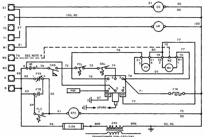
PROBLEM 13 Heat pump control circuit.