AMAZON multi-meters discounts AMAZON oscilloscope discounts
INTRODUCTION
A basic understanding of motors is essential to under standing motor control and why it is necessary. Generating electrical energy and using this energy is basic to our industrial structure. Motors or electrical machinery can be found everywhere in applications often over looked: automobiles, turntables, electric pencil sharpeners, elevators, and computer printers. Each of these applications has a different control requirement.
MOTORS
There are two major categories of motors, AC and DC, but there are many ways to construct and connect the internal windings of these motors. Generators operate on the same principle and are often included in the same discussions. DC motors and DC generators are practically impossible to tell apart by appearance. Both have the same parts—armature core, armature windings, commutator, brushes, and field poles (see FIG. 1). There are three basic types of DC motors, determined by how the field windings are connected: series, shunt, and compound. The selection of the type of motor to use is determined primarily by the requirements of the
load. In a series motor, the field circuit is in series with the armature, whereas the shunt motor is connected in parallel. A compound motor has two sets of field windings, one connected in series and one connected in parallel. These different types of connections are shown in FIG. 2. DC motors are rated by voltage, current, speed, and horsepower.
The operation of all motors is essentially the same and is based on the principles of magnetics and its interaction with conductors. Currents are caused by conductors cutting magnetic fields set up in the windings of the motor. The field poles produce this magnetic field, and the armature windings are the conductors. The field poles are either permanent magnets or electromagnets. To use the electrical energy produced by the spinning armature, a method must be developed to connect to the wires in these windings. Obviously, it would not take too many spins for the wires to become hopelessly tangled if a connection were made directly to the wire. Instead, a method must be used that makes contact but still allows the armature to turn freely. As a result, sliding contacts, or slip rings, are connected to the ends of the conductors. These slip rings, in turn, make contact with carbon blocks called brushes, which are connected to the commutator to transfer the electrical energy to the output terminals. FIG. 3 demonstrates how slip rings are connected.
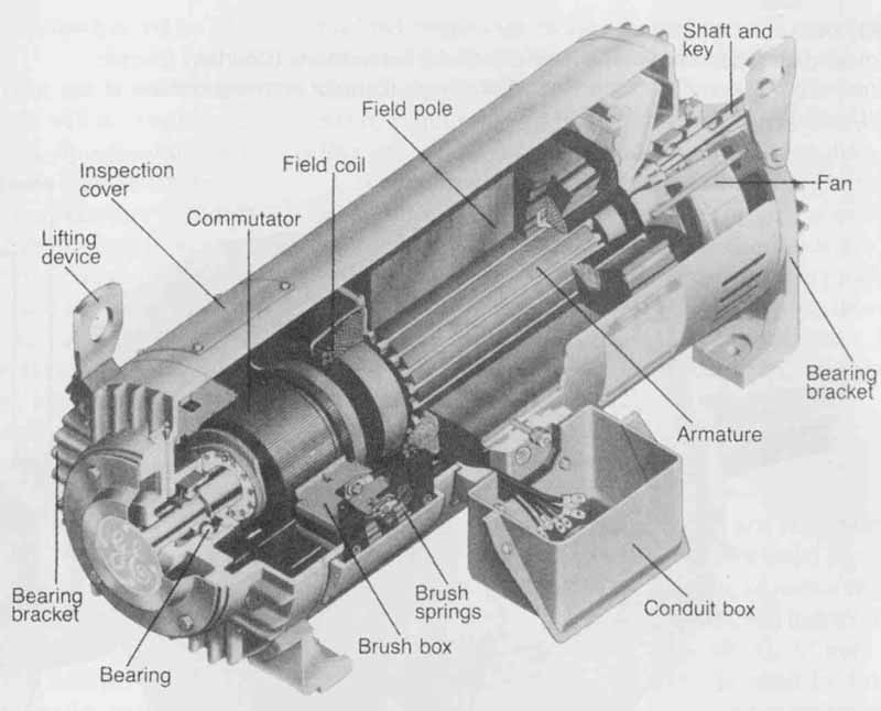
FIG. 1 Cutaway of DC motor. (from General Electric Company)
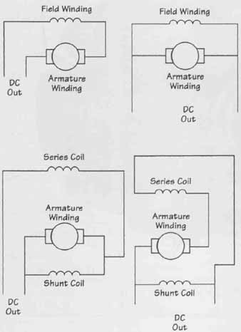
FIG. 2 Connecting the field windings in series, parallel, or a combination
of the two.
DC Motors
DC generators and motors can be grouped into many different categories based on different characteristics of the motors: type of winding, size, type of magnet, and so on. The simplest type of motor uses a permanent magnet and is sometimes referred to as a PM generator or PM motor. Such a motor has the advantage of being small and light. It is also the most efficient, since no power is required to generate the magnetic field. The primary applications of these motors and generators, however, must be low-current situations. Too large a current through the armature windings will produce a magnetic field that could be large enough to demagnetize the field magnets. Electromagnetic fields can either be externally excited or self-excited.
The way the field coil is connected will produce different output results. For example, a series-connected coil will produce higher-output voltage for higher-output currents. Shunt-wound motors or those with the field coil connected in parallel produce almost constant output voltage, regardless of the output current. This situation is easy to understand when you realize that in a series-connected motor the field coil is in series with the output. If the output current increases, the field current also must increase, producing a stronger magnetic field and creating a higher induced voltage. When the coil is connected in parallel, it is unaffected by output current.
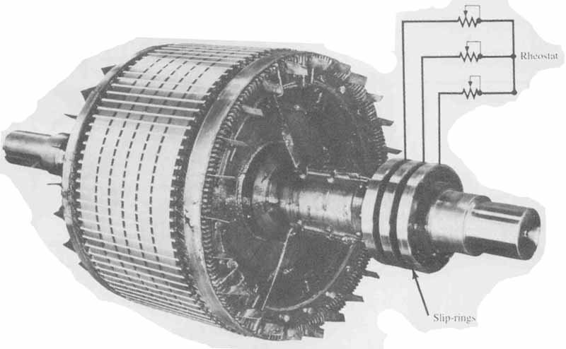
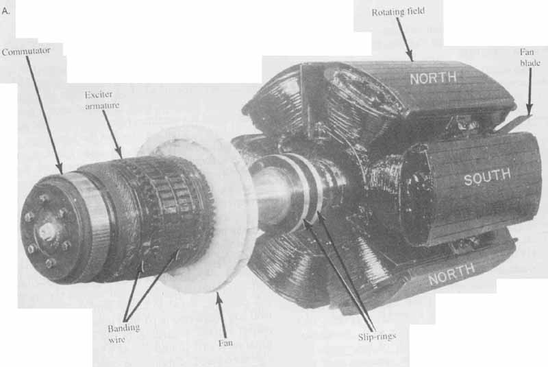
FIG. 3 (A) Wound-rotor induction motor showing rheostat connections
(Electric Machinery Operations of Dresser— Rand Company); (B) rotor showing
location of slip rings. (General Electric Company)
Each type of motor has its own set of advantages and disadvantages. The application will determine the type of motor that needs to be used. Shunt-wound motors provide good speed regulation, easy reversibility, and ease of braking. The main disadvantage is that if the field current is interrupted while the motor is turning, but not under load, the motor increases in speed until it reaches a runaway state, where it can literally fly apart. Series-wound motors are probably the most common. The primary advantage is that they are small and light. Because the field coil has high current, it requires fewer turns of wire, resulting in less expense and lighter construction. Series-wound motors provide the most horsepower for their size.
A series-wound motor can also be used with either AC or DC because the polarity of the field windings and the armature windings both reverse, and the magnetic force remains in the same direction. For this reason, series-wound motors are often called universal motors. Series motors do not adapt easily to dynamic braking, however. Starting torque is very high; as a result, starting current is also very high. Speed regulation is poor under varying loads. Runaway can occur under no-load conditions. Series motors provide excellent results in high-speed operations, but these operations can cause considerably shorter life spans and higher maintenance requirements. For this reason, series-wound motors are usually not designed for continuous duty.
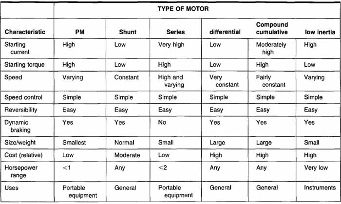
TABLE 1: Summary of DC Motors and Their Characteristics
Compound-wound motors can be used to provide a combination of the characteristics of series- or shunt- wound motors. Depending on how the fields are connected, different operating characteristics are produced. Compound motors are more expensive but are desirable for high-torque, constant-speed applications. Table 1 gives a summary of the types of DC motors and some of their operating characteristics.
AC Motors
The majority of motors used today are AC. Many of these are the universal type that can be used for either AC or DC applications. Another type of motor that has the same advantage of low cost and is even more reliable is the induction motor (see FIG. 4). Motors constructed using induction eliminate the need for brushes and thus lower the maintenance cost. The two principles used in induction motors are rotating magnetic fields and induced voltages. Even though AC induction motors have parts similar to those of DC motors, the construction is slightly different. An AC motor has a stator and a rotor, rather than a field and armature. These produce very similar results, but may have different construction. The rotor is made of very thick rods, rather than the thinner windings found in other motors. These rods are connected in such a way as to resemble an exercise wheel for a small animal. Because of this, they became known as squirrel-cage motors (see FIG. 5). The stator windings are grouped much differently than the armature windings. They are divided into three equal groups 1200 apart, and each of these groups is connected to a separate phase of the three-phase power. When you look at this type of motor, however, all the wires look as if they are uniformly distributed. The rotor is located in the middle of the magnetic fields. As the fields “move” past the conductors in the rotor, a current flow and an induced voltage are created. The magnetic action between the rotor and the rotating field causes a starting torque and makes the rotor rotate without any electrical connection. This results in a very depend able and easy-to-maintain motor. If the rotor is constructed so that it is almost parallel to the rotation axis, it will provide much more uniform torque and reduce noise during operation.
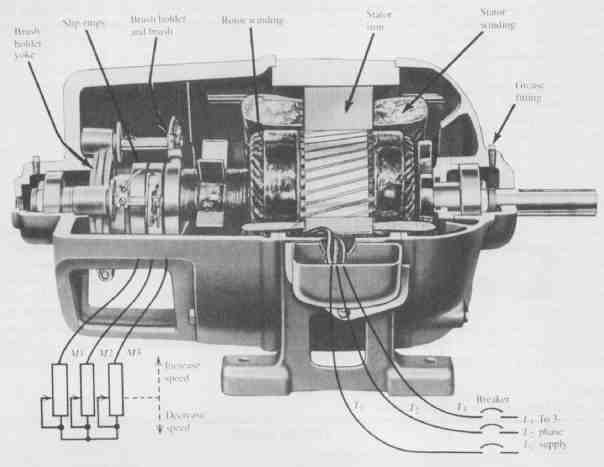
FIG. 4 Cutaway of a wound-rotor induction motor. (Magnetek Louis Allis
Company)
The wound-rotor induction motor is significantly different in construction from the squirrel-cage induction motor. Each rotor conductor is insulated and lies in slots very similar to the DC armature windings. Also, the grouping of the rotor windings is very definite and can be identified by inspection. They are usually wound for three phases with a Y connection and must have the same number of poles as the stator. Wound-rotor induction motors also have slip rings to allow banks of resistance to be connected easily to each phase of the rotor. If the resistance in this bank of resistors is set to zero, the motor will operate just the same as a squirrel- cage induction motor. Adding resistance to the rotor of the wound-rotor induction motor is a method of speed control. The advantages of this type of motor include increased starting torque with less starting current. However, the cost of producing this type of motor increases significantly with the addition of brushes, insulation of the rotor windings, slip rings, and the resistance bank. These motors are less efficient with a greater power loss in the rotor and have poorer speed regulation. The speed control available through the resistance bank is not very good at low-load conditions. However, wound-rotor induction motors are very useful when high starting torque and long starting periods are required. In today’s applications, the DC motor is found more and more often. The use of solid-state controls enables the use of DC motors to provide a wide range of speed control, good speed regulation, and higher starting and running torque with much lower starting currents.
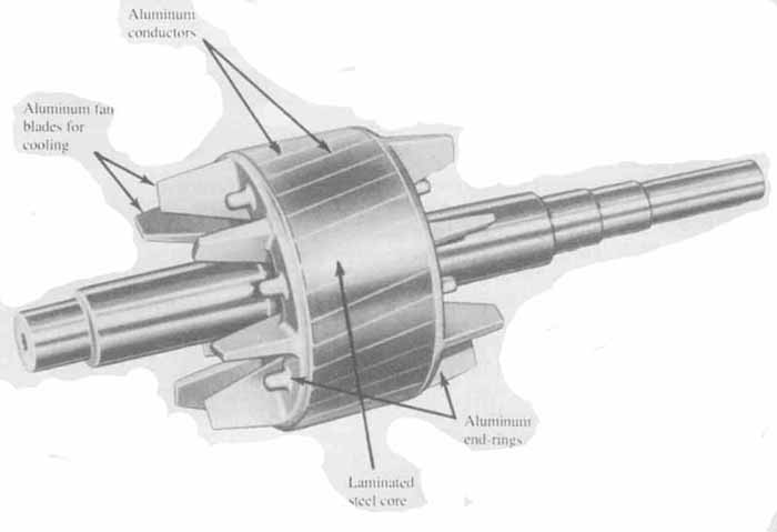
FIG. 5 Squirrel-cage motor. (Siemens Energy and Automation)
Braking of induction motors can be accomplished very simply by applying DC to the field windings. This causes a stationary magnetic field, rather than a rotating one. When the rotor attempts to follow this magnetic field, the result is very quick braking. One big disadvantage of induction motors, however, is speed variation. The speed of an induction motor depends directly on the physical design and the frequency of the AC power used for the field windings. It is practically impossible to alter this frequency, since it uses the standard generated frequency for all power consumption. So, the primary method for varying speed is to make changes to the physical design of the motor itself. Increasing the number of coils per pole decreases the rotation speed of the rotor. There are trade-offs with this type of modification to the actual construction of the motor. If additional windings are added, the motor becomes larger, more expensive, and less efficient.
For applications in industry where three-phase power is available, the polyphase induction motor is widely used. The polyphase induction motor is typically cheaper and more efficient than a single-phase induction motor. It is also able to produce a higher starting torque with a smaller starting current. Whenever possible, a polyphase motor is preferred however, when three- phase power is not available, a single-phase motor must be used.
To gain some of the advantages of a polyphase motor using single-phase power, a split-phase motor can be used. Two sets of windings are used in this type of motor, one for starting and one for running. The start winding is smaller-gauge wire, which provides a higher resistance. The run windings have more inductance, and this inductance causes a phase shift between the magnetic fields to increase the starting torque. They are designed so the starting windings will drop out after the motor has reached 70% of its operating speed. If they did not, these windings would overheat from the continuous high currents through the starting windings. One big disadvantage in the use of this type of motor is a lower starting torque than with a true polyphase motor. The low torque is due to only a 60 degree phase difference between the start and run coils. A larger phase difference is found in the polyphase motor.
If a capacitor is added in series with the start winding, a greater phase difference can be obtained, resulting in a higher starting torque. Such motors are called capacitor-start motors. Like the start winding, the capacitor is used only during the actual starting. Both the split- phase and the capacitor-start motor (see FIG. 6) need a method for dropping the start windings or the starting capacitor once the 70% operating speed has been reached. To disconnect the power from these, two methods are generally used: a centrifugal switch or a current relay. Unfortunately, these devices cause maintenance to increase, since they tend to fail with time and use. If a larger wire is used for the start winding, the start winding can continue to be in the circuit all the time, which eliminates the need for the switch or relay. Such a motor is called a permanent-split-capacitor motor. The windings are referred to as capacitor windings and main windings instead of start and run. This type of motor has the advantage of increased reliability, since the starting switch or current relay is eliminated and has smoother, but somewhat lower, starting torque. To increase the starting torque, a second capacitor can be added, which adds the expense of a second capacitor, as well as for the switch or current relay. Each type of motor has its advantages and disadvantages, and the type chosen will be the one that is optimal for the individual application. A summary of AC motors and their characteristics is given in TABLE 2.
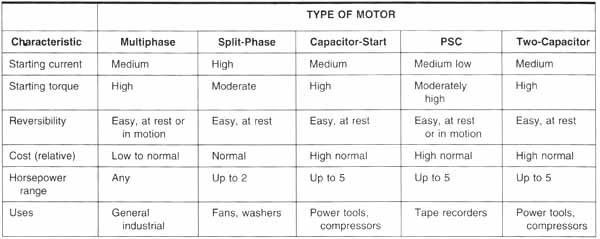
TABLE 2 Summary of AC Motors and Their Characteristics
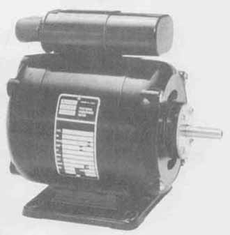
FIG. 6 Capacitor-start motor.
As you can see, the selection of a motor depends greatly on the type of application and the various different operating characteristics provided by the motor it self. The factors for choosing motors are not really within the scope of this book. A general knowledge of motors is helpful in producing drawings and understanding the documentation that is required to accompany those drawings. Motors, like many other parts encountered in the drawing experience, have ratings and standards. In this case they are provided by the National Electrical Manufacturing Association (NEMA), and most manufacturers use this code when identifying their motors and control components.
CONTROL CIRCUITS
When motors are used in circuits, there must be a method of controlling the motors. Control can be as simple as a method for starting and stopping—a switch that provides line voltage or removes it. Typically, however, a little more than that is required.
Control circuit voltages are often lower than the voltages used for the motor. There are two primary reasons for using a lower voltage: safety and the need to standardize on values for control devices. In most control circuits, single-phase 120V is used. To get from the line voltage to a usable control voltage, a step-down transformer is used. The symbol for a transformer is shown in FIG. 7. The coil connected to the line voltage is called the primary and the coil connected to the control circuit is called the secondary. Both the primary and the secondary can have a single coil or more, de pending on the ratio between the two. Because the transformer is not capable of generating power, the power on the primary side must be equal to the power on the secondary side. Remember that power is the voltage times the current. So, if the voltage is being stepped down, the current will be stepped up by the same ratio.
Protective Devices
In addition to the power for the motor and the control circuit, protective devices are required. Fuses, disconnect switches, and circuit breakers are used to disconnect the energy from the circuit. The disconnect switch is often a three-pole switch ganged together so that all three lines can be disconnected at the same time with a single handle. These devices are shown in FIG. 8.
Protection for circuits can be provided by fuses, circuit breakers, or thermal overloads. Fuses and circuit breakers perform similar functions. They are both used to break the circuit and stop current flow if an unsafe condition occurs. Another device used to open an unsafe circuit is called simply an overload device. This device is sometimes called a thermal overload because the contacts will open due to high temperatures. It is often found in motors and motor starters. Fuses can be standard, one-time fuses that must be replaced after they trip or they can have a renewable fuse link. Time-delay fuses are used when heavy overloads may occur for a short period of time, such as high currents during starting. In this case, the circuit must remain closed, but if for some reason the high current remained for a sustained period, this fuse would trip and the circuit would open.
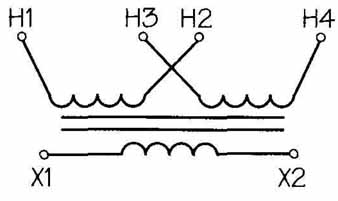
FIG. 7 Symbol used for a transformer.
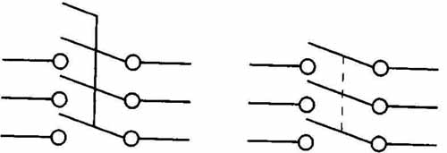
FIG. 8 Disconnect switches ganged together so that they all operate
at one time.
In some applications a short circuit even for a fraction of a second could cause dangerously high currents and result in damaged equipment. In these cases, the current-limiting fuse is used. The symbols used most often to represent fuses, circuit breakers, and overloads are shown in FIG. 9.
Switches
Circuit breakers are used for load switching as well as protection. There are a number of different kinds of circuit breakers, both nonautomatic and automatic. The nonautomatic kind is used as a disconnect or a circuit interrupter for load switching and isolation. These circuit breakers can have a thermal strip added for automatic tripping. A thermal trip unit has a time lag or delay, since it depends on temperature rise. A momentary overload would not trip this circuit breaker. If there is a short-circuit situation, a much faster means must be used to disconnect power. A magnetic trip unit is used to trip instantaneously on a short circuit or even a momentary overload. A combination of the two units is often desirable, since a magnetic trip works best with short-circuit high currents and a thermal trip works best with sustained overloads. FIG. 10 shows the symbols for circuit breakers with thermal overload and magnetic trip units included. For three-phase applications, these circuit breakers can be ganged together and disconnected manually with a single handle.
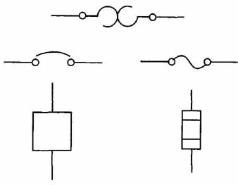
FIG. 9 Symbols for thermal overloads, circuit breakers, and fuses.
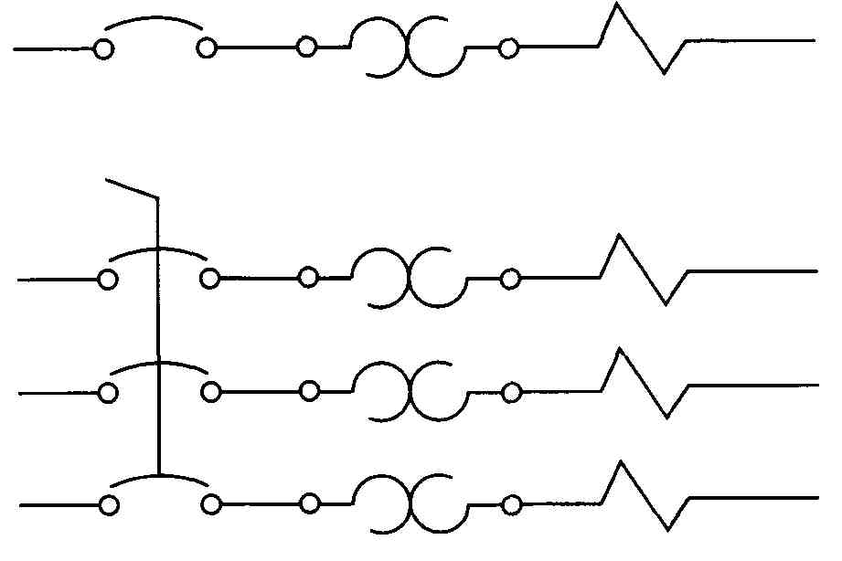
FIG. 10 Symbols representing a circuit breaker with thermal overload
and magnetic disconnect for both single-line and three-phase application.
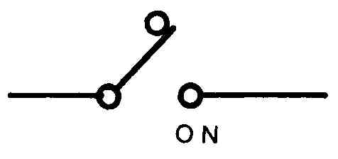
FIG. 11 Two-position, single-pole, single-throw switch.
Disconnect switches are used primarily to connect and disconnect the primary power lines. They are not used to start and stop motors. Start and stop switches come in a large variety of sizes and shapes, with many different types of operators or actuators. They can be manual or automatic, momentary contact, normally open, or normally closed. In some applications the color of the operator is critical. Certain colors have become associated with certain functions. For example, red is generally used for stop switches and green is used for start switches. Although the symbols are not necessarily different, the switch symbols are used more extensively in control circuits. More types of switches are used. Each different type of switch requires a slightly different symbol. All switches indicate that some contact is made and also indicate a direction of movement, or throw, for the switch. Switches are identified by the number of poles, or contacts, that they can make and the throw, or number of directions in which they can be moved. For example, a typical switch used to control the overhead lights is called a single-pole, single-throw switch. It is represented by the switch shown in FIG. 11. The switch can be opened or closed, but makes contact with the circuit in only one direction; therefore, it is single throw. This same switch symbol could be used to represent a single-pole, double-throw switch if the switch were used as a selector switch and if the off contact were connected to another line. Since most overhead lights need to have only one wire opened to stop current flow, the single-pole designation means it is connected to only one wire. Opening and closing the switch makes or breaks contact for that wire; hence, it is single pole. Switches are used to make and break contact manually, as in the light switch, automatically, as in liquid level, pressure, or flow, or by many other means. A switch that is used to indicate liquid levels, or a float switch, is not the same as a switch used to indicate pressure or temperature. Symbols for different types of switches are shown in FIG. 12. For a more complete list of switches available, search Google for "electrical switches symbols " .
Automatic switches are used for controlling many different kinds of circuits. A level switch may start a pump when a fluid level is too high or too low. A limit switch may stop a conveyor belt when an object passes a certain point. A proximity switch can stop machinery when a person or object moves within a danger zone.
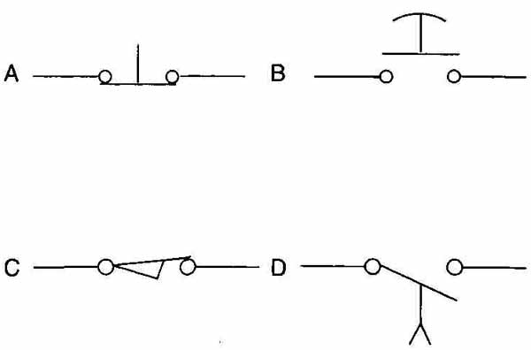
FIG. 12 Methods to represent different types of switches graphically:
(A) momentary contact, normally closed; (B) momentary contact mushroom
head, normally open; (C) limit switch, normally closed; (D) time delay,
normally open, timed closing when energized.
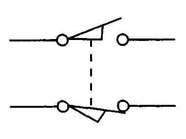
FIG. 13 Mechanical connection between two contacts of a limit switch,
represented by dashed line, indicates that when one is open the other
must be closed.
Switches are identified as having normally open and normally closed contacts. Although these are not electromechanical devices, they are mechanical devices that can be wired as normally open or normally closed; both sets of contacts can even be used. In the situation when both sets of contacts are used, the mechanical relation ship or connection between the two is often indicated with a dashed line, as seen in FIG. 13; this line means that when one switch is open the other is closed, and vice versa.
Another important component in some control circuits is the indicator light. These lights are used in many applications either to indicate that power is applied to a circuit or to warn of a dangerous or alarm situation. As with the push button, different colors for different lights are generally accepted to mean certain things. Red is almost always used for dangerous or alarm situations and green or clear is used for normal operating conditions. Indicator lights are drawn as shown in FIG. 14. The letter in the circle represents the color of the lens, which can be glass or plastic. Sometimes the slash marks are not included, and only the letter indicating the color is used. In this case, it is important to include a comment on the diagram to identify it as a lamp and perhaps note what a lighted condition indicates.
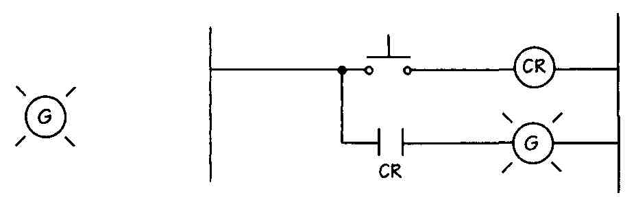
FIG. 14 Symbol for an indicator light and its use in a typical circuit.
Control Devices
Control relays, time delay relays, and contactors are all used in control circuits. The relay is an electromechanical device, a combination of electrical and mechanical functions. An electrical current passing through the relay causes a corresponding mechanical action. As the name implies, the relay device consists of a coil of wire formed from a number of turns of wire wrapped around a magnetic core. When a current is caused to flow through the coil, a magnetic field is established and the coil becomes an electromagnet. The mechanical function of the relay coil occurs when this magnetic field is established. A set of contacts is located close to the magnetic coil, and the magnetic action causes these contacts to be either pulled together or pulled apart. These contacts are used to make and maintain a complete circuit or to break a circuit. Many relays have multiple sets of contacts. These contacts will be either normally open (NO) or normally closed (NC). When the relay is at rest or is de-energized, these conditions exist. Contacts are always drawn in their de-energized state so that when you are analyzing a circuit you will know that a normally open contact will close when the relay is energized. The symbol for contacts is two parallel lines, as shown in FIG. 15, and the symbol for the coil portion of the relay is a circle with a letter to help identify it. Many different letters are used to indicate the coil. CR is often used to identify a control relay, but it is just as common to use other letters, such as an M for motor starter, TR for timed relay, or simply F and R for forward or reverse direction of motor movement. The control relay should not be confused with a motor starter, which is discussed a little later in this Section. Also, the control relay should not be confused with the motor itself. There is little chance for that when the entire circuit is shown. Company policy will often dictate the lettering identification needed for a set of control relays, but, if not, the two basic things to remember are to keep the identification simple and to be consistent in the method you use.
FIG. 16 shows a simple control circuit with two relays, three normally open contacts, and an indicator light. Notice that the contacts are labeled showing to which relay they are connected also, they are numbered sequentially. No contacts are shown in this small portion of a circuit for the second control relay. 1CR-1 is used to “hold” or “seal” the circuit closed after 1CR is energized. This is referred to as an interlock contact and maintains the circuit after the start button has been released. Contact 1CR-2 is used to complete the circuit to the indicator light, and contact 1CR-3 completes the circuit so that coil 2CR is energized. It is obvious that this is only a portion of a larger control circuit, since it would be pointless to include a control relay that was not used to control anything.
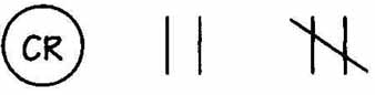
FIG. 15 Symbol for a control relay and two sets of contacts, one normally
open and one normally closed.
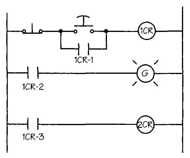
FIG. 16 Simple control circuit with two relays, three sets of contacts,
two switches, and an indicator light.
In some applications a small delay may be required between the time a relay is energized and the contacts are activated. The delay could come in four different configurations. For example, it could be a delay after energizing or a delay after de-energizing. The configurations are as follows:
1. Normally open, time delay on closing
2. Normally closed, time delay on opening
3. Normally open, time delay on opening
4. Normally closed, time delay on closing
The first two represent a time delay when energized, since normally open contacts close when energized and normally closed contacts open when energized. This same principle is applied to the second two. The symbols for these configurations are shown in FIG. 17.
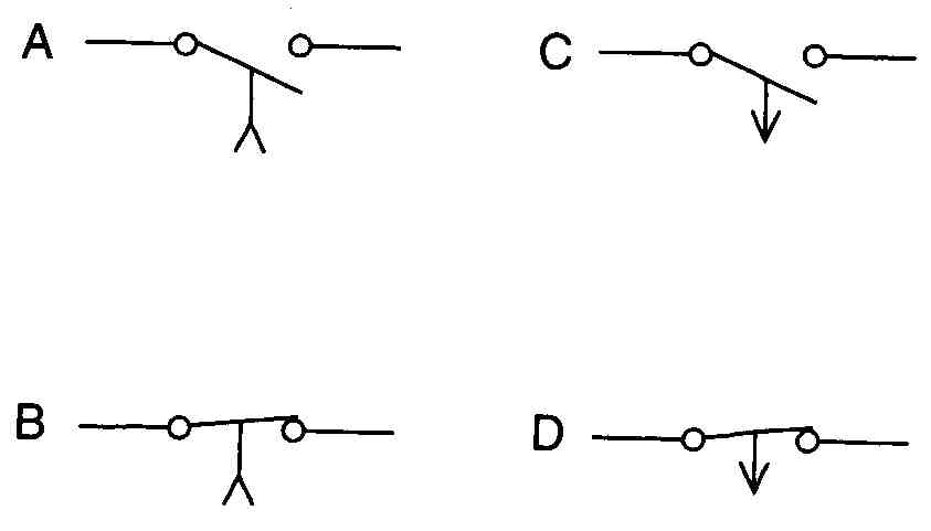
FIG. 17 Symbols for various time delay configurations: (A) normally
open, time delay on closing; (B) normally closed, time delay on opening;
(C) normally open, time delay on opening; (D) normally closed, time delay
on closing.
Note that the symbols used to represent the time delay contacts look like switches. Also, when discussing switches, contacts are often mentioned. The interchanging of reference to switches and contacts is understand able when you remember that each of these devices performs the simple task of opening and closing, or completing, a circuit.
The contactor is also an electromechanical device; it works in the same way as the control relay. A contactor also has sets of normally open and normally closed contacts. The primary difference between a contactor and a control relay is the size and type of load they are able to control, Contactors are used for much heavier currents and are capable of handling up to 2250 A. They can be found in high-resistance or heavy industrial solenoid applications. The symbols used for contactors are the same as those used for control relays. If separate overload circuit protection is available, a contactor can be used to start and stop motors.
Most often, however, an actual motor starter is used. A motor starter is very similar to the control relay and the contactor. It is an electromechanical device with contacts that operate when a coil is energized. The primary difference between them is that motor starters generally have built-in overload protection. These motor starters come in a range of sizes (see FIG. 18) and are used in single-phase, two- and three-phase, and also three-phase, four-wire applications. There are manual motor starters that provide overload protection but very limited control. Most often, motors require some remote operation and added control safety and convenience. In such cases a magnetic motor starter is used. Overload relays are added to the motor starter and are generally thermal elements. The biggest need for protection for motors is for sustained periods of heavy load. Thermal overload protection allows high currents to pass for a period of time and then trips open and removes power from the starter coils. When the coil de-energizes, its contacts open and disconnect the motor from the live power. Remember that overload relays do not protect motors or control circuits from an instantaneous short circuit. This type of protection requires the use of circuit breakers or fuses. Most motor starters have three sets of load contacts for use with three-phase motors and an additional high-current auxiliary con tact. This auxiliary contact is often used to provide the interlock contact around the start switch. The contact is often called the seal-in contact and, when energized, is said to seal the start circuit.
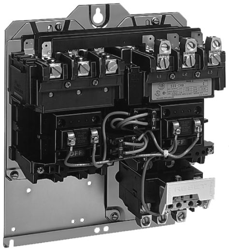
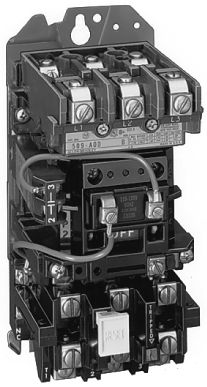
FIG. 18 Full-voltage starter. (From ab.com)
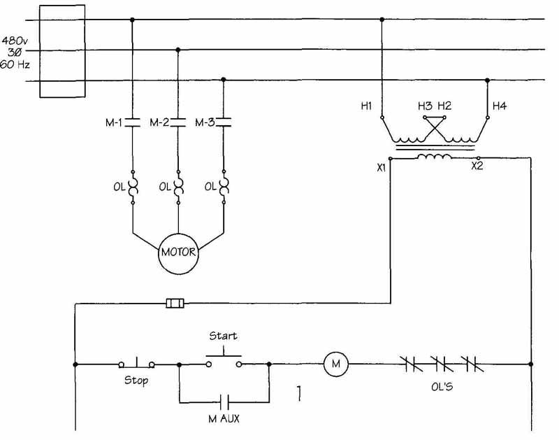
FIG. 19 Simple motor and control circuits representing full-voltage,
across-the-line starting.
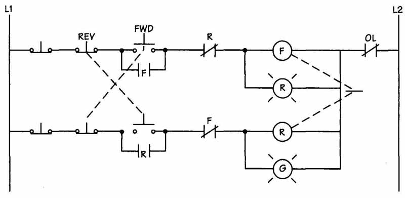
FIG. 20 Simple motor control circuit representing both forward and reverse
control with mechanical interlock between the two coils.
Starters
There are many different types of starters in the following categories: full voltage, reduced voltage, reversing, and multispeed.
Full-voltage or across-the-line starters are the simplest form of control and the simplest to draw. A complete circuit showing the control and motor portions is given in FIG. 19. Note the step-down transformer used to go from 480 to 120V for the control circuit.
Reversing motor starters need an additional motor starter with another set of contacts to reverse the connections on two phases of the motor. Note the sets of normally closed contacts shown in FIG. 20 next to each motor starter. This is an electrical inter lock to prevent both motor starters from being ener gized simultaneously. In addition, a mechanical inter lock is often used. The start switch in each motor- starter branch is mechanically linked so that when one closes the other one opens. This mechanical interlock is demonstrated by the dashed lines shown in the illustration.
The terms two-wire control and three-wire control are often used to describe control circuits. Unfortunately, it is not as simple as two wires versus three wires. The concept is, however, not too difficult to understand. FIG. 21 shows both a two-wire and three-wire control circuit. Another way to describe the two different circuits is no-voltage or low-voltage release and no-voltage or low-voltage protection. In a two-wire system, or low-voltage release, if for some reason the line voltage drops out the motor will stop. If the contacts on the control device, such as a pressure switch, limit switch, and so on, are still closed when the line voltage returns, the motor will restart. For three-wire control circuits, or low-voltage protection, when the line voltage is removed, the coil de energizes and the interlock contact drops out. In this circuit the motor will not start again until the start button is pushed. A three-wire circuit can provide additional safeguards to keep the motor from restarting after a power loss or unsafe condition. However, the disadvantage of this type of control circuit is that some physical intervention is required to restart the circuit.
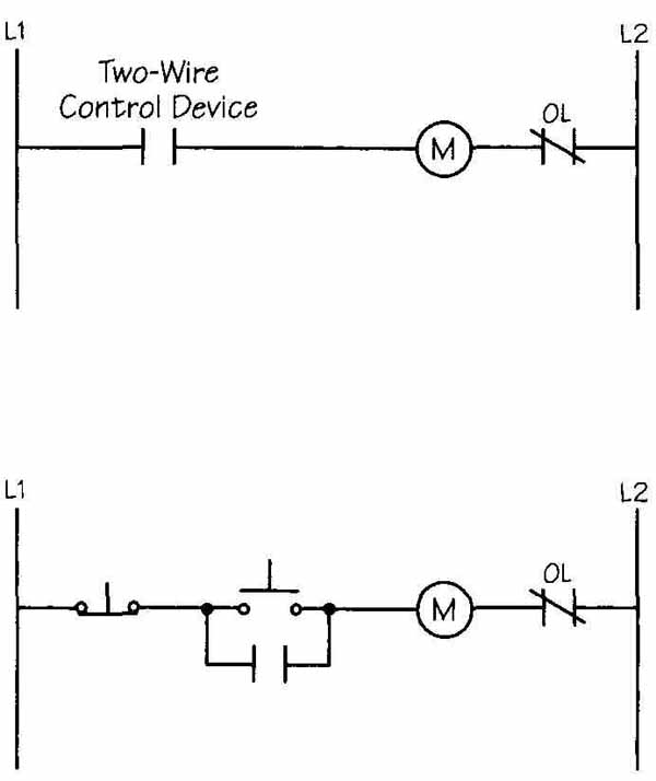
FIG. 21 Two-wire control circuit versus three-wire control circuit.