Customize analog meter faces with your PC and a laser printer.
By SKIP WITHROW
EVEN IN TODAY'S WORLD OF DIGITAL electronics there are still times when an analog meter is the better choice for displaying voltage, current, or other signal levels.
With the use of a personal computer and a laser printer, this article shows how you can customize analog meters from your junk box or local surplus dealer to display almost any scale and units. Gone are the days of trying to draw meter scales by hand; you can make your computer and laser printer do the work for you.
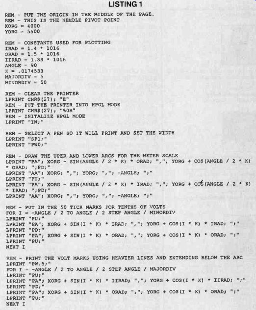
Any laser printer that under stands HPGL (Hewlett-Packard Graphics Language) commands is compatible with the techniques presented here. The BASIC programming language is used to assemble the commands which are then sent to the printer. The printer prints the new scale on a whole-page laser label and then the label is applied to the old meter. Figure 1 shows a meter, purchased for $2 at a surplus electronics out let, before and after modification.
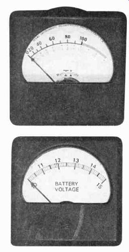
FIG. 1--A VOLTMETER, purchased for $2 surplus, shown before (top) and after
modification (bottom).
Finding the right meter
The first step to successfully making a newly labeled meter is to start with the right meter. Al though many meters can be found for very reasonable prices in the surplus market, not every meter is a candidate for a new scale. Several specifications, such as the full-scale current and the meter movement's resistance, are helpful in deter mining whether the meter is a suitable choice.
To change the scale of a meter, the face must be accessible. Some inexpensive meter movements have cases that can't be opened, and these should be avoided. Generally the cover of a meter face can either be removed by simply prying it off, or by removing several small screws on the outside of the meter. The second task is to remove the meter face itself.
Again, some inexpensive meters might have their faces mounted permanently, but the majority of meters have several small screws that hold the meter face in place. The ability to remove the meter face is essential.
Other things that must be known about the meter before it can be used in a circuit properly are its full-scale current and the resistance of its movement coil.
For a new meter, these are easy to determine from the meter's specification sheet. Sometimes you will be lucky enough to find information printed on an old meter face that will help deter mine the full-scale reading.
If you know nothing about a meter's electrical specifications, they can be determined rather easily. Generally most meters have a full-scale current between 100 microamperes and 1 milliampere. Coil resistance generally varies between about 40 and 1000 ohms. The setup to measure full scale current and coil resistance is simple. The value of the power supply is not critical. A potentiometer between the supply and the un known meter should be large enough to limit current to about 50 microamperes (about 200K). First set the potentiometer to its maximum value, turn on the power supply, then de crease the resistance until the meter reads full scale. Measure the voltage of the supply and the value of the variable resistance.
The voltage divided by the resistance will then give you the current required to deflect the meter full scale.
Another potentiometer can determine the meter coil resistance. With the meter indicating full-scale current, place a 1K potentiometer across the meter and adjust until the meter reads exactly 1/2 scale. Remove this potentiometer and measure its value. This will be the value of the coil resistance of the meter.
The meter in Fig. 1 had a full scale current reading of 229 microamperes and a coil resistance of 819 ohms.
Making faces
A protractor is the best tool for measuring the total angle of movement of the meter needle, which generally runs from 90 to 120 degrees. Also measure the distance from the pivot point to the scale of the old meter face and the location of the face plate mounting holes with respect to the pivot point. Those measurements will be input to the program that draws the new meter face.
The next step in putting a new face on your meter is to carefully remove the old meter face plate. After opening up the meter case it is usually just a matter of removing the small screws holding the faceplate on. A set of jeweler's screw drivers can sometimes be helpful for particularly small meters. Once the face plate is loose it can be removed by very carefully sliding it from under the needle of the meter. Be careful not to bend or bump the needle.
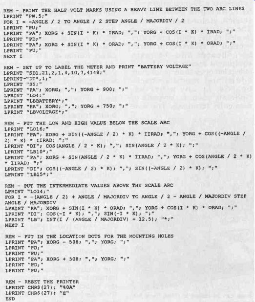
------ LISTING 1
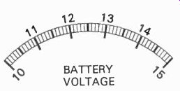
FIG. 2--THIS METER FACE is the result of the BASIC program in Listing
1.
Using HPGL
HPGL is a graphics language of short, simple statements that allows lines, arcs, and text to be drawn. Originally developed for plotters, this language has been incorporated into many of to day's laser printers. By using just a few of the many HPGL statements, professional looking meter scales can be created with customized features.
The BASIC language can send HPGL commands to the printer for drawing the various features of the scale. Using a computer language to send the commands to the printer is helpful because many commands can be generated using program loops with an incrementing variable. This lets rather short programs generate many different individual graphic elements to compose the new meter face plate.
Listing 1 is the BASIC program that draws the meter face in Fig. 2. Only a few of the many HPGL commands are used in the program. Most are two-letter commands followed by arguments. In Listing 1 many of the arguments are calculated by the BASIC program. The program plots points on a graph that has 1016 points (pixels) per inch in both the X and Y directions.
Here's a list of the commands that are used and short descriptions:
IN-Initialize SP-Select Pen PW-Set Pen Width PA-Plot Absolute AA-Arc Absolute PU-Pen Up PD-Pen Down SD-Standard Font Definition DT-Define Label Terminator SS Select Standard Font LO-Label Origin LB-Label
The syntax of those commands is explained in the technical reference section for the HPGL language in your printer manual. Since some commands take X and Y coordinate locations, some simple trigonometry is used to calculate the arguments from the index angle in the program of Listing 1.
Developing your own meter face is a simple matter of running the program and printing the resulting graphics on the printer. You probably won't get it right the first time, but making modifications is easy. Writing the program in blocks that add a new graphic after each iteration works best. Printing locating marks on the new face for the mounting holes helps to align the new face properly on the old face plate.
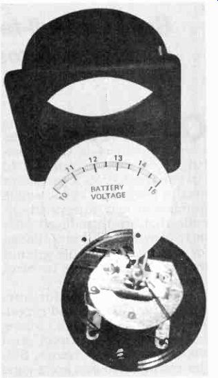
FIG.3--HERE IS THE NEW LABEL pas ted onto the surplus meter.
Once everything looks the way you want it to on paper, print the results on a full-page laser label. It's best to apply the new label on the reverse side of the old face plate since it's usually a nice clean surface. Punch pinholes in the location marks to help locate them from the back side of the label. Peel off the backing of the new scale la bel and place the label face down. Then stick the face plate to the label, lining up the locator holes in the center of the face plate mounting holes. After applying the label use a modeling knife to trim the excess paper from around the meter face plate and mounting holes. Figure 3 shows the new label applied to the old meter.
Reassembly finishes the job.
Carefully slide the face plate under the meter needle and replace the mounting screws. Next, re place the meter cover.
Creativity is the key to adding an exciting meter display to your next project. Expanded-scale voltmeters are an ideal application for this technique.
Power supply current meters are also nice to have. This technique can also create non-linear meter scales such as decibel meters for audio or RF applications. Meter recycling can enhance your projects with just a small investment in time.
adapted from: Electronics Now--Electronics Experimenter's Handbook 1996