By ROBERT A. HEIL
Measure low resistances with this super simple circuit that connects to your DMM.
THE MILLIOHM ADAPTER ALLOWS resistances from 1 milliohm to 1 ohm to be measured with a high degree of accuracy on any digital multimeter. The circuit loads the device under test with a current of 100 milliamperes at 5 to 6 volts. The adapter connects to a DMM that is set on its millivolt--or 2-volt scale.
Ohm's law says that resistance equals voltage divided by current, or R = V/I. Thus, a DMM reading of 5.7 millivolts would correspond to 0.057 ohms. (5.7 mV/100 mA = 57 milliohms or .057 ohms.)
Circuit description
The milliohm adapter circuit, shown in Fig. 1, is powered from a 9-volt battery. A resistor to be tested (Rx) is connected across banana jacks J1 and J2, and a pair of banana plugs, connected directly to J1 and J2, plugs into the voltage input jacks of a DMM. Switch S1 applies battery power to 7806 voltage regulator IC1.
Capacitor
C1 removes voltage transients. Resistors R1 and R2 form a voltage divider for the ground pin of IC1. Potentiometer R2 trims IC1's output voltage to exactly 6-volts DC. Potentiometer R3 sets the output current through Rx to 100 milli amperes. Because R3 is a relatively large resistance compared to Rx, the error introduced by different values of Rx (1 milliohm to 1 ohm), or the effect it will have on the 100-milliampere current source, is below 2%.
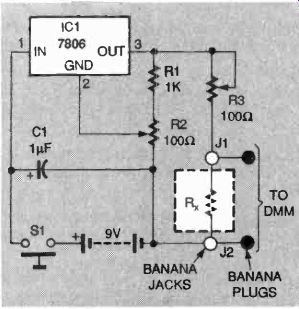
FIG. 1—MILLI-OHM ADAPTER CIRCUIT.
A resistor to be tested (Rh) is connected across banana jacks J1 and J2, and a pair of banana plugs, connected directly to J1 and J2, plugs into the voltage input jacks of a DMM.
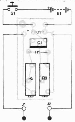
FIG. 2-PARTS-PLACEMENT DIAGRAM.
This circuit is simple enough to point-to point wire.
Construction
A PC board is available from the source given in the Parts List, but the project is also easy to breadboard. You must select a case for the project before be ginning the assembly. The prototype's case measures approximately 2 by 3 1/4 inches and is about 1 inch deep. The case has an aluminum cover.
A parts-placement diagram is shown in Fig. 2. Stuff the board as indicated, and check your work before continuing. remove the covers from the banana plugs and place them into the common and the volt/ohms terminals of your DMM. Dab some petroleum jelly or other similar substance on the ends of the jacks protruding from the DMM. With the lid attached to the project case and facing up, press the upper left back of the plastic case onto the ends of the plugs stuck in the DMM. The petroleum jelly will transfer onto the project case and will mark the hole locations for drilling, allowing the adapter to plug directly into the DMM. Permanently mark those locations be fore continuing. Then turn the case over and similarly mark the locations on the lid of the case for the two banana jacks directly above the holes for the plugs.
-----------
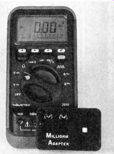
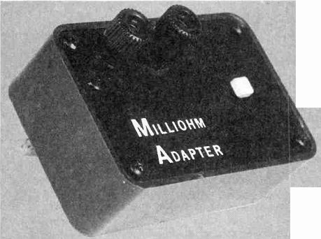
------- THE ADAPTER looks like it was custom made for this meter.
PARTS LIST
R1--1000 ohms
R2, R3--100 ohms, 20-turn potentiometer
C1--1 uF, disc capacitor
IC1-7806 6-volt regulator
B1--9-volt battery
S1--SPST momentary switch
J1, J2--banana jack/plug combo
Project case (Radio Shack No. 270-230 or similar unit).
PC board, wire, solder.
Note: the following items are available from RAH Projects, P.O. Box 15904, N.B., CA 92659:
Etched and drilled PC board-$3.95 plus return postage
Parts kit including PC board (no case)--$10.95 plus $2.50 S&H
Check or money order, only. California residents please add sales tax. Allow 4 to 6 weeks for delivery. Personal check orders will be shipped after the funds have been cleared.
------------
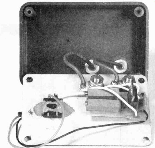
FIG. 3-THE INSIDE of the completed unit. The case is large enough to contain
the 9-volt battery.
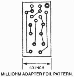
---------- MILLIOHM ADAPTER FOIL PATTERN.
Drill appropriately sized holes in the case bottom and lid for the banana plugs and jacks. Be sure to use insulated jacks if your case has an aluminum .... nal plug covers. Next install the cover. Solder a 3-inch piece of test lead wire to each banana plug and install them in the bottom of the plastic case with No. 10-32 nuts instead of the origi .... banana jacks in the case cover.
Mount the PC board on the cover as close to the jacks as possible. You can secure it with No. 4-40 hardware on one corner with a plastic spacer.
Any momentary switch will work in the circuit, but make sure there's enough room in the case for the 9-volt battery. The battery connector can be made from an old 9-volt battery. remove the old battery case and cut the leads from the cells to the connector at the top. Solder on new wires, and keep in mind that the small connector is now negative and the large one is positive.
Attach the negative side of the battery to the negative PC board input and the positive side to one side of the momentary switch. Solder another wire from the remaining side of the momentary switch to the positive PC board input. Solder one output from the PC board and one banana plug wire to a spade lug on the back of one banana jack. Do the same for the other jack. Figure 3 shows the inside of the completed unit.
Calibration
With the cover still off, plug the adapter into the DMM and set the range of the meter to 20 volts. Press S1 and adjust R2 for 6 volts DC. Next, place an am meter across the banana jacks and adjust R3 for a reading of 100 milliamperes. To calibrate the circuit when used in con junction with test leads, short circuit the leads together and write down the reading; then subtract that reading from any readings you take with the test leads. Now get out that junkbox and start testing those components with unknown values.