by JOHN PIVNICHNY, N2DCH
Build this world band receiver and enjoy performance that is superior to many store-bought models.
HAVE YOU LISTENED TO WORLD band (shortwave) broadcasts and found that you enjoyed them but were disappointed because your receiver was unable to hold onto the station you wanted? Perhaps only a few minutes passed before the station faded or was swamped out by another one. If you've now become a fan of world-band radio but would like better quality reception, the SWX6 receiver is the project for you to build.
Many inexpensive world-band shortwave receivers promise a lot, but they rarely deliver.
New shortwave listeners are never sure whether the problem lies in the antenna, circuitry, or if the time of day had an effect on listening conditions. Many of the inexpensive receivers suffer from poor channel selectivity, poor image frequency rejection, and drift-weaknesses that make listening a strain.
Those problems are not present in up-scale receivers like the SWX6 receiver. The SWX6 delivers performance that many of the high-priced rigs, but it can be built for less than $100 worth of parts with the plans in this article. Because digital frequency synthesis is not used in the SWX6, it's a good project to build if you want to learn (or get a refresher course) in the basics radio-frequency circuitry.
Leading features Figure 1 is a simplified block diagram of the receiver. The incoming radio frequency (RF) is filtered by the bandpass filter and mixed with the output of the crystal oscillator in the first mixer. After passing through the 16.45 to 17.1 MHz filter and being amplified by the first intermediate frequency (IF) amplifier, the signal is mixed with the output of the variable frequency oscillator (VFO) in the second mixer.
The signal is then passed through the 9.83-MHz crystal filter before being fed to the second IF amplifier, which is under the control of the AGC circuit.
The detector converts the RF signal to audio and the audio amplifier amplifies it, giving the listener a choice of loudspeaker or headphones.
The received signal is kept essentially distortion-free by the six -pole crystal filter which provides good selectivity, bandpass filters which handle image rejection, and a very stable, low-drift analog tuning oscillator.
This circuit is so stable, you will never have to readjust the dial once a station is tuned in! The double conversion circuitry provides ample IF gain.
The fast-responding automatic gain circuit (AGC) reduces fading all the way down to an actual null. Separate bandpass filters for each of the six bands provide excellent rejection of out-of-band signals and signals at the image frequencies. As a result of all these features, this receiver is easy to operate and makes for pleasurable listening.
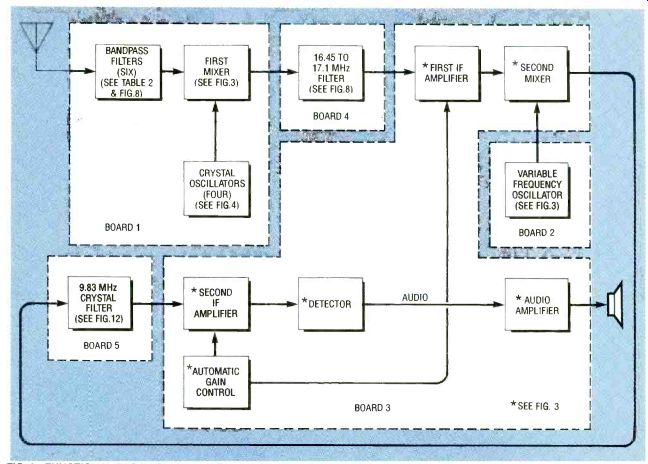
FIG. 1--FUNCTIONAL BLOCK DIAGRAM OF SWX6 RECEIVER showing the partitioning
of circuits on three principal circuit boards.
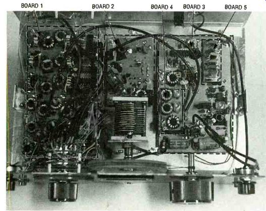
FIG. 2--VIEW OF THE INSIDE OF THE SWX6 RECEIVER showing the relative
positions of the three principal and two piggy-back circuit boards.
Figure 2 is a photograph of the inside of the prototype SWX-6 receiver showing the details of its modular construction. Conventional etched circuit boards are not used in building the SWX6. The circuitry is assembled on five blank copper-clad laminate circuit boards with the copper foil side facing up to serve as a common ground plane. Component leads pass through holes drilled in the board for interconnection and soldering on the bare side.
Copper foil is removed around all drilled holes by countersinking to provide adequate isolation from ground.
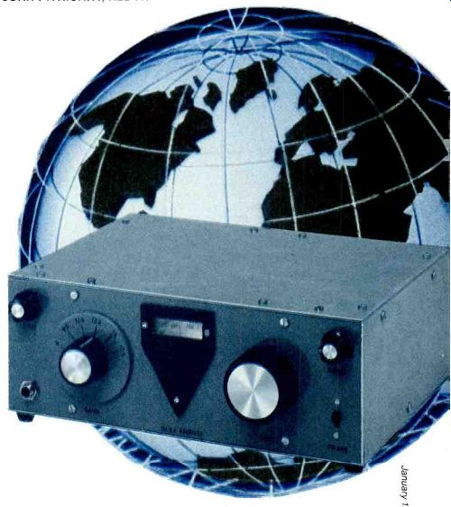
The SWX6 is organized to receive six bands: 6, 9.5, 11.5, 13.5 15 and 17.5 MHz. These bands are marked on a plate behind the BAND knob. The diamond-shaped tuning bezel at the center of the panel is part of the tuning assembly that includes a moving dial behind the window and the TUNE knob to the right. There is a GAIN knob at the upper left, a speaker or headphone jack at the lower left, an AUDIO knob at the upper right, and a POWER switch at the lower right. The audio amplifier can drive either a speaker or headphones with a resistance of 4 to 16 ohms.
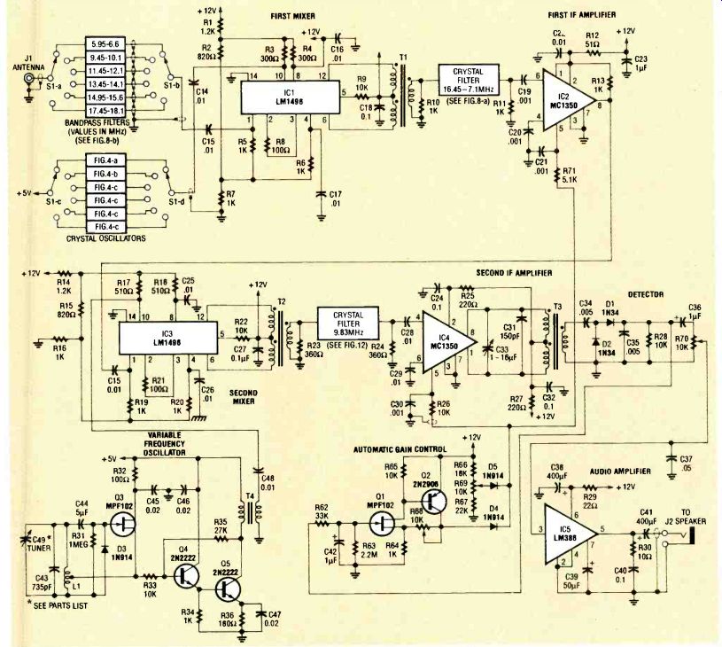
FIG. 3--SCHEMATIC FOR THE SWX6 RECEIVER with the principal functional
circuits labeled. Makre all connections between the contacts of switch
S1-a and the bandpass filters with enameled magnet wire.
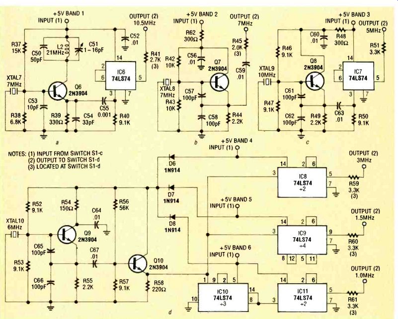
FIG. 4--SCHEMATICS FOR THE CRYSTAL-CONTROLLED oscillators that tune
the six bands of the receiver.
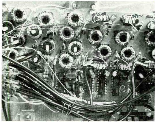
FIG. 5 FILTER /MIXER BOARD layout with coaxial cabling and other wiring
to the band switch shown in foreground.
First mixer and IF Figure 3 is the complete schematic for the SWX6 receiver.
The first mixer converts each of the popular shortwave bands to the 16.45 to 17.1 MHz range.
The heart of this stage is IC1, an MC1496 balanced modulator/ demodulator. A double-balanced mixer with separate bandpass filters for each band provides excellent performance.
A separate crystal oscillator/ divider is included for each band, permitting the use of inexpensive, readily available, microprocessor timebase crystals for excellent stability. Also, separate oscillators are easier to build than a synthesizer, and they give better wideband noise performance. The schematics for these crystal oscillators are shown in Fig. 4.
For example, on band 1, to tune 5.95 to 6.6 MHz, the local oscillator must apply a 10.5 MHz signal to convert this range to 16.45 to 17.1 MHz. For this band see Fig. 4-a. The oscillator tripler circuit has a 7 MHz crystal (XTAL7). It is followed by a divide-by-two integrated circuit, IC6, a 74LS74. (A low-cost 10.5-MHz microprocessor timebase crystal was not available.) Frequencies for the other bands are shown in the diagrams 4-b through 4-d.
As shown in Fig. 3, the MC1350 monolithic IF amplifiers IC2 and IC4 amplify in both the first and second IF amplifier stages. The first MC1350, IC2, follows the first mixer stage and 16.45 to 17.1 MHz band-pass filter. This wideband amplifier increases the level of all signals within this 650-kHz range. Note that the gain input pins, Pin 5, of each IF amplifier are fed by the output of the AGC section. However, the first IF amplifier is fed with 5.1K resistor, R71, while the second IF amplifier is fed with 10K resistor, R26.
------------------

TABLE 1 DIMENSIONS FOR CIRCUIT BOARDS AND ENCLOSURE PANELS
Function Circuit boards 1 Length (in.) Width (in.)
1. First mixer bandpass filters, oscillators
2. Variable frequency oscillator
3. General circuitry
4. 16.45 to 17.1 MHz filter
5. 9 .83 MHz crystal filter 6 3 5 3 23/s 31 2 3 1 1
Enclosure panels 2
1. Top and bottom
2. Front and back
3. Two sides 3 10 9.9 7 7 3.5 3.5
Notes 1: Blank single-sided copper-foil laminate
2: 0.060-inch thick sheet aluminum
3: Allow for insetting the side panels
---------
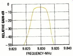
FIG. 6--CRYSTAL FILTER RESPONSE curve showing relative gain in decibels
vs. frequency in kilohertz.
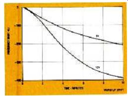
FIG. 7--CURVE SHOWING DRIFT IN FREQUENCY of tuning oscillator during
10-minute warmup period.
---------
This difference ensures that there is more gain reduction of strong signals in the first amplifier, thus preventing possible overloading of the input of the second IF amplifier. Gain reduction will occur whether it is due to the manual GAIN control R69 on the front panel, or automatically due to AGC response on reception of strong signals or those that fade in and out.
One filter per band A separate bandpass filter for each band removes image signals and ensures that any signal outside the desired band is sharply reduced prior to mixing at the first oscillator. Further rejection occurs in the first IF bandpass filter prior to any amplification. Only signals in the selected band get through.
The separate bandpass filters for each of the bands are built on board 1, the largest of the five circuit boards in the receiver (see Fig. 1) shown in Fig. 5. This filter-mixer board measures 3 1/4 x 6-inches and it contains the oscillator /divider circuits for each band and the first mixer circuit. (Schematic diagrams for the bandpass filters are included along with a table of component values for the six bands later in this text.) The tuning oscillator and isolation amplifier are built on board 2, a 2 x 3-inch board, and the general circuitry is built on board 3, a 3 x 5 inch-board.
The two smaller boards (4 and 5) with coils and crystal holders are mounted piggy-back on board 3.
The three principal circuit boards are mounted on the aluminum baseplate for the enclosure. The front, back, top and side panels are also cut from the same sheet aluminum and joined with aluminum angle stock, nuts and bolts.
The crystal filter response curve showing relative gain in decibels vs. frequency in megahertz is shown in Fig. 6. This curve helps to explain why stations can be received so clearly as you tune across them. There is essentially no adjacent-channel feed-through. Stations are received loud and clear, limited only by propagation strength, not by the wide limits of a ceramic IF filter like those found in inexpensive receivers.
Construction procedure
The first step in the construction of the SWX6 receiver is to cut the five circuit boards to size. These are cut from copper-clad laminate circuit board stock in accordance with Table
1. Carefully drill 0.060-inch holes in the four corners of the three largest boards for later mounting to the chassis base-plate with screws and nuts stacked for use as standoffs. Set the boards aside for later parts-placement planning and lead-hole drilling.
It is also advisable to cut (or have cut) the enclosure panels from the 0.050-inch thick sheet aluminum stock to the sizes specified in Table 1. Drill or form a 1 1/2 x 1/2-inch dial window in the front panel on the center line 1/2-inch down from the top.
Plan the location of all panel-mounted components (e.g., rotary BAND switch, GAIN and AUDIO potentiometers, TUNE dial) in the front panel and drill or form their mounting holes.
Drill or form the holes for mounting the antenna jack in the back panel.
Cut the 1/2-inch aluminum angle stock to size, and drill all the holes in all the panels and angle stock necessary to bolt the panels together to form a secure enclosure. Assemble it after you have completed mounting all of the panel mounted components and circuit boards, and completed all board-to-board and board-to-panel component wiring.
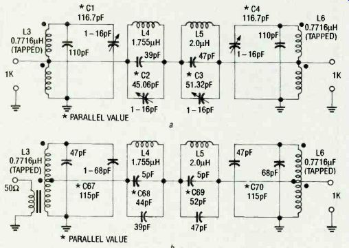
FIG. 8--SCHEMATICS FOR THE BANDPASS and the five other bands, b. FILTER
fsr the 16.45 TO 17.1 MHz band, a,
You might want to complete the tuner assembly before building the circuitry. Holes must be drilled in the baseplate to mount the tuning capacitor and in the front panel to mount the bezel and the dial window on opposing sides of the cutout in the front panel. A complete section covering this part of the project is given further on in the text. You might also want to finish painting some of the aluminum enclosure panels before mounting any of the components on them.
----------------
All resistors are ¼-watt, 5 % unless otherwise specified.
R1, R14-1200 ohms R2, R15-820 ohms R3, R4, R48-300 ohms R5, R6, R10, R11, R13, R16, R19, R20, R34, R64-1000 ohms R8, R21, R32-100 ohms R9, R22, R26, R28, R33, R42, R43, R6510,000 ohms R12-51 ohms R17, R18-510 ohms R23, R24-360 ohms R25, R27, R58-220 ohms R29--22 ohms R30-10 ohms R31-1 megohm R3527,000 ohms R36-180 ohms R3715,000 ohms R38-6,800 ohms R39-330 ohms R40, R46, R47, R50, R52, R53, R579100 ohms R41-2700 ohms R44, R49, R55-2200 ohms R45-2000 ohms R51, R59, R60, R61-3300 ohms R54-150 ohms R5656,000 ohms R6233,000 ohms R63 -2.2 megohms R6618,000 ohms R6722,000 ohms R6810,000 ohms, trimmer R69, R7010,000 ohms, potentiometer, panel-mount R71-5100 ohms
Capacitors C1, C4-116.7 pF (110 pF in parallel with Parts List 1 -16 pF trimmer, Mouser 24PX016 or equivalent)
C2-45.06 pF (39 pF in parallel with 116 pF trimmer, Mouser 24PX016 or equivalent)
C3-51.32 pF (47 pF in parallel with 116 pF trimmer, Mouser 24PX016 or equivalent)
C5, C7, C9, C11,-66pF (56pF in parallel with 10 pF) C6, C10-49.7 pF (47 pF in parallel with 2.7 pF) C8-68 pF C12, C13-180 pF C14, C15, C16, C17, C22, C24, C25, C26, C28, C29, C48, C52, C56, C59, C60, C63, C64, C670.011.1F C18, C24, C27, C32, C40-0.1µF C19, C20, C21, C30, C550.001 uF C23, C36, C42-1.0 µF, electrolytic C31-150 pF C33, C51 -1-16 pF trimmer, Mouser 24PX016 or equivalent C34, C35-0.0051.11 C370.05µF C38, C4140011F, electrolytic C39-50µF, electrolytic C43 -735 pF (three 220 pF in parallel with 75 pF, silvered mica or NPO ceramic C44-5 pF, ceramic NPO C45, C46, C470.02µF C4910-140 UNIT air dielectric tuning, Fair Radio Sales No. C12/T784 or equivalent (surplus item)
C50-50 pF C53-10 pF C54-33 pF C57, C58, C61, C62, C65, C66-100 pF C67, C70-115 pF (47 pF in parallel with 68 pF) C68-44 pF (39 pF in parallel with 5 pF) C69-52 pF (47 pF in parallel with 5 pF)
Semiconductors IC1, IC2MC1496 balanced modulator/ demodulator (Motorola) or equivalent IC3, IC4MC1350 monolithic IF amplifier(Motorola) or equivalent IC5 -LM386 audio amplifier (National Semiconductor) or equivalent IC6, IC7, IC8, IC9, IC1174LS74 Dual D flip-flop (Texas Instruments) or equivalent IC1074LS90 decade counter, (Motorola) or equivalent
Q1, Q3MPF102 N-channel FET transistor Q22N3906 PNP transistor Q4, Q5-2N222 NPN transistor Q6, Q7, Q8, Q9, Q102N3904 NPN transistor D1, D2-1N34 D3, D4, D5, D6, D7, D8-1N914 Crystals XTAL1, XTAL2, XTAL3, XTAL4, XTAL5, XTAL69830,4 MHz XTAL7, XTAL8-7.0 MHz XTAL9-10.0 MHz XTAL10-6.0 Mhz Switches S1four-pole, six-position rotary, Mouser 10WR046 or equivalent S2slide, panel mounted, power Transformers T1, T2-16 turn 30 AWG trifilar on FT37-61 core, Amidon or equivalent T3-10 turn, 26 AWG trifilar on T37-2 core, Amidon or equivalent
Parts List
T4 primary 25 turns 26 AWG, secondary 5 turns 26 AWG on FT-37-43 core, Amidon or equivalent Inductors L1-12 turns 18 AWG on T-50-6 core (3 terns tapped from ground end), Amidon or equivalent L2-18 turns, 26 AWG on T-30-10 core, Amidon or equivalent XXX L3, L6-13 turns, 18 AWG on T-50-6 core (6 1/2 turns tapped from ground end) Amidon or equivalent L4-21 turns , 22 AWG on T-50-6 core, Amidonm or equivalent L5-22 turns, 22 AWG on T-50-6 core, Amidon or equivalent
Connectors
J1coaxial jack, S0239 or equivalent J2-phone jack, mono
Miscellaneous: 28 T-50-6 powdered-iron toroid cores, Amidon or equivalent, six aluminum panels, 0.060-inch thick cut per Table 1, five copper -foil covered circuit boards cut per Table 1, four feet of RG-174/U coaxial cable, tuning capacitor mounting bracket (see text), 30 inches of V2 X 1/2-inch aluminum angle stock, reels of enameled magnet wire -18, 26, and 30 AWG, insulated hookup wire, 0.25-inch thick acrylic plastic, 4 x 4-inch for pulley (see text), 0.10-inch thick acrylic plastic for bezel, dial window, and rotary switch plate (see text), 30 inches of nylon cord, four knobs for front-panel manual controls, four rubber feet with self tapping screws, No. 4-40 nuts bolts as required, solder
------------------

FIG. 9--CHARACTERISTIC CURVE FOR BANDPASS FILTER showing relative
gain in decibels vs. frequency in megahertz.

TABLE 2--BANDPASS FILTER DATA
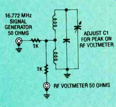
FIG. 10--TEST SETUP TO TEST THE END CAPACITOR.
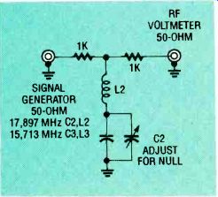
FIG. 11--TEST SETUP TO ADJUST CAPACITORS C2 and C3.
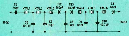
FIG. 12--SCHEMATIC FOR CRYSTAL FILTER showing the interconnection
of 9830.4 kHz crystals and individual or parallel capacitors where
needed to achieve desired values.
Electronic circuitry
It is recommended that the receiver be built as a series of modules that are individually completed and tested before final assembly and wiring. None of the circuits in this receiver is particularly challenging, and construction should be well within the skill level of the amateur who works with care and attention to detail.
Printed circuit boards were not used to build the SWX6 receiver circuitry so it will be necessary for you to plan the locations of all components on the boards before doing any assembly and soldering. After establishing a component layout pattern, drill all of the holes necessary to insert the leads of the components through the boards.
The components are mounted on the copper-clad surface of the board by drilling 0.040-inch holes at the proper locations for all leads with a No. 60 drill. Countersink all holes with a 1 /8-inch drill to remove the copper foil back to a radial distance of at least 0.050-inch around the drilled holes to provide suitable isolation and insulation around the leads. It will be necessary to drill rows of holes for mounting the IC's.
Component interconnection is done on the back or bare side of the substrate with the wire from the component leads. In cases where the leads are of insufficient length to span the distances required, 30 AWG insulated hookup wire should be used.
Build the audio amplifier first, and then work back toward the antenna terminal: second IF amplifier and detector, automatic gain control, second mixer and so on until you get back to the first mixer.
To test the audio amplifier, put your finger on the input jack and listen for the AC hum with the headphones. For a more precise indication of its performance, feed in an audio signal and verify with an AC voltmeter that the gain is 40 with the volume control set full open.
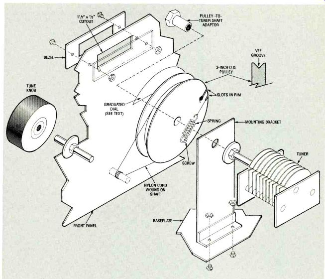
FIG. 13--EXPLODED VIEW OF DIAL DRIVE and tuning assembly with locking
bearing.
Referring to Fig. 3, build the second IF amplifier and detector. The variable capacitor across the output transformer, C33, should be set by feeding a 9.83 MHz signal into the input of IC4 at pin 4. With a DC voltmeter on the detector to automatic gain control (AGC) line, tune for a peak.
Variable-frequency oscillator Build the variable-frequency oscillator (VFO) circuit on board 5, the 2 3/8 X 1-inch board listed in Table 1. The peak radio-frequency output voltage of the VFO amplifier measured at C48 should be 300 millivolts. Stability can be checked by monitoring the circuit with a frequency counter from a cold start. A typical drift curve for this circuit is shown in Fig. 7.
For optimum stability, the VFO should be powered by a 5volt DC supply rather than the 12-volts used elsewhere in the receiver. A three-terminal 5-volt regulator on the output of the 12-volt supply can provide the 5volts. The frequency of the VFO should be set to 6.670 MHz with the dial set at 0 by adjusting the turn spacing on L1. This can be checked later by listening for WWV at 10 MHz on band 2 (9.5) or 15 MHz (15) on band 5.
Bandpass filter
After the second mixer is complete, you will have a tunable receiver covering the 16.45 to 17.1 MHz range. Now build and install the 16.45 to 17.1 MHz bandpass filter. Refer to the schematic, Fig. 8-a. Build this bandpass filter on board 4, a 1 x 3-inch piece of copper-clad, single-sided board stock so that it can be easily removed. See Table 1.
The crystals need not be matched if they are certified to be within the proper tolerance and purchased from a reliable vendor. Solder the crystals and disc capacitors in place, interconnect them, and mount the filter on the main circuit board with bare hookup wire.
To restrict the signals reaching the second mixer to the 16.45 to 17.1 MHz band, the 16.45 to 17.1 MHz crystal filter is placed ahead of the first IF amplifier. Figure 8-a is the schematic for this filter and Fig. 8-b is the schematic for the five other bandpass filters. All of the bandpass filters are wound on T-50-6 powdered-iron toroid cores, selected to have inductance Q's over 200. Ceramic capacitors are specified for use in the filters. Four variable capacitors are in parallel with fixed capacitors to form C1 through C4 in the 16.45 to 17.1 bandpass filter to set those capacitance values precisely.
Figure 9 is a plot of the band-pass characteristic for the 16.45 to 17.1 MHz filter. The relatively steep skirts in this filter are produced by the two parallel resonant circuits (C2, L4 and C3, L5 in Fig. 8 -a) in the center series arm. This is the most important bandpass filter in the receiver and it must be aligned correctly.
Check the filter in the receiver by listening with the headphones for a stable signal within the 16.45 to 17.1 MHz range.
The 11th harmonic at 16.5 MHz of the band 5 (refer to Fig. 4-d) oscillator / divider output of 1.5 MHz will be satisfactory.
Tune across the band while monitoring the DC voltage on the detector AGC line. The voltage rise very rapidly to more than 5 volts, hold steady, and then drop rapidly to zero.
With a frequency counter connected to capacitor C48 and a voltmeter calibrated in decibels on the AGC line, verify that your filter output matches the curve in Fig. 9.
Obtain an RF signal generator and an RF voltmeter.
Mount the four inductors on the copper-clad side of the 1 x 3-inch board 4. Then connect the end capacitors (fixed and variable) as shown in Fig. 10. lb check the LC resonant circuit at each end, set the RF generator to the filter's mid frequency (16.772 MHz) and adjust the 116 pF capacitor in parallel with the 110 pF capacitor that forms C1 for a peak reading (parallel resonance) on the RF voltmeter.
Now connect inductor IA and the two capacitors forming C2 (a 39 pF capacitor in parallel with a 1 to 16 pF capacitor) shown in Fig.11. Set the RF signal generator for 17.897 MHz, and adjust for a null (series resonance). Repeat this step with L5 and C3 tuning for a null at 15.713 MHz. Then without changing capacitor settings, connect the filter components in their final positions as shown in Fig. 8-b. Frequencies for the other bands are shown in Table 2.
The first mixer converts each of the popular shortwave bands to the 16.45 to 17.1 MHz range.
The mixer in this receiver is a double-balanced mixer.
Filter construction Build the four crystal-controlled oscillators that tune the six bands of the receiver by referring to the schematics in Fig. 4. Note that 7 MHz-crystals are used in both the band 1 and 2 oscillators (XTAL 7 and XTAL 8), but a 10 MHz crystal (XTAL9) is used in the band 3 oscillator (Fig. 4-c). The oscillator in Fig. 4-d is able to provide three different frequencies because of its output countdown circuitry (IC8, IC9, IC10 and IC11). Filter details are given in Table 2. Filters are built with fixed-value capacitors and tuning is accomplished by adjusting the position of the wire turns on the toroid cores. Compressing the turns to less than 360 degrees of the toroid's circumference increases their inductance and lowers their resonant frequency.
For example, compressing a coil whose turns are spread out over 360° down to about an angle of coverage of about 120 degrees increases the inductance 75 %, shifting the frequency 32% lower. Follow the procedure outlined for the first IF band-pass filter, but use the frequencies listed in Table 2. Filter components are mounted directly on the 6 x 3 1/4-inch circuit board 1. (See Figs. 1 and 2.) Automatic gain control Refer to Fig. 3 and build the automatic gain control (AGC) circuit last. It allows this receiver to cope with a wide range of signal strengths while the listener tunes across the band.
The volume control knob can be left in a fixed position and all tuning can be done with the TUNE control.
Set the 10K potentiometer, R68, for 5 volts DC at the cathode of diode D5 with no signal input to the receiver. This level will increase to about 6 volts in the presence of strong signals, causing a reduction in the gain of the IF amplifiers. Refer to Fig.
12 and build the 9.83 MHz crystal filter on board 5 whose dimensions are given in Table 1.
Precision tuning dial Cut and bend a mounting bracket for the air -dielectric tuning capacitor C49 from aluminum stock and drill a hole in it to accept the capacitor shaft and two holes at its base flange 1/4 inch back from the front edge so it can be mounted to the baseplate as shown in Fig. 13.
(Capacitor C49 is part of the variable frequency oscillator circuit.) Mount tuning capacitor C49 on the bracket positioned about 1 1/4 inches behind the front panel as shown in Fig. 13. The tuning capacitor is rotated by an assembly shown in Fig. 13 consisting of a 3-inch diameter pulley turned by a nylon cord wound over the tuning knob spindle and located in the vee groove of the pulley.
The pulley can turned from sheet plastic in a lathe or a suitable one might be obtained from electronic salvage. Two slots cut in the edge of the pulley allow the cord ends to pass through the wall of the vee groove for fastening. A small spring at one end keeps the cord in tension over the pulley. A screw in the edge of the pulley approximately 120° away from the slots will anchor the other end of the spring. Fasten the pulley to the tuner shaft with a suitable adapter.
A pattern for the precision dial is given here. It can be photocopied from the magazine page and cemented to the front face of the dial pulley as shown in Fig. 13. Cut a suitable bezel from 1/2-inch sheet plastic to form an appropriate frame for the dial window. The inside of the bezel should be cut and filed to match the 1 1/2 x 1/2-inch cutout in the front panel, but there are no restrictions on the outside dimensions of the bezel. Be sure the bezel sidewalls are wide enough to permit it to be fastened to the front panel with screws and nuts.
Paint the dial window bezel before assembling it to the front panel. In the prototype, the clear plastic was painted black to match the color of the knobs.
Scribe a vertical line on the piece of clear plastic to be used as a window over the rotary dial and behind the slot cut in the front panel. With a sharp black felt-tip pen carefully trace over the scribed line so that it will appear as a distinct hair line to serve as the cursor.
Place the painted bezel on the outside of the front panel and the scribed window on the inside (with the cutout window in the front panel between them) and assemble them with screws and nuts. Wind on the nylon drive cord as shown in Fig. 13 and fasten it to the spring.
Power supply
The prototype SWX6 receiver was powered by a regulated 12volt power supply. The receiver draws about 75 milliamperes, so any source of 12 volts, including batteries, at that current level can be used. Provision must be made, however to obtain the 5 volts DC to power the variable frequency oscillator.
Enclosure finishing
Assemble the three principal circuit boards to the base plate of the enclosure with No.4-40 machine screws and two No. 4-40 nuts used as spacers in the positions shown in the photograph Fig.5.
Complete all wiring. Make the connection from the antenna jack J1 to the wiper of switch S1-a with RG-174/U coaxial cable, and make all connections from the six terminals of switch S1-a to the six filters (detailed in Table 2) with enamel-coated magnet wire. Then make all connections from the output side of the filters to the contacts of S1-b with RG-174/U coaxial cable. Also, connect the S1-b wiper contacts to capacitor C15 with RG-174/U coaxial cable.
Make the following connections with insulated wire: Five volts to the wiper of S1-c Six terminals of S1-c to each of the oscillators shown in Fig. 4 The six output connections from the oscillators S1 -d Make the following connections with RG-174/U coaxial cable: Wiper of switch S1-d to C14 Electrolytic capacitor C41 to speaker/headphone jack J2 Enclosure assembly Mount the front and back panels on the base panel with angles, nuts and bolts. The side panels should be assembled with angles set so they are concealed behind the left and right edges of the front and back panels, under the left and right edges of the top panel, and over the side edges of the baseplate.
In the prototype, dry-transfer labels were applied to identify the manual controls. A separate circular plastic band switch plate was used to identify the band positions on the multi-deck switch. (This plate can be easily changed if you want to change the band positions or frequencies.) Clear lacquer was applied over the dry labels to protect them. Install four rubber feet on the bottom of the base plate with sheet metal screws to prevent the exposed screw heads from scratching the table on which the receiver is located.
R-E
Also see: Crystal Oscillators