(cont. from part 1)
11. Pit-Stop--The Indy of Electronics
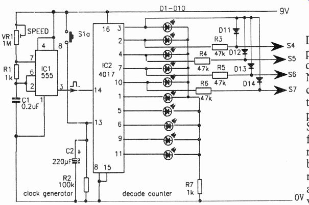
Fig. 19-Circuit diagram for the Pit-Stop counter circuit.
Pit-Stop is a motor-racing game that can be played with up to four competitors, the winner being the first driver past the checkered flag after a pre-arranged number of laps. The rules are simple and to the point. A driver can move away from the starting grid only when he has tanked up. Fueling and moves (distance round the track) are determined by an electronic indicator, the number of moves depending on skill in selecting the numbered LEDs that flash in sequence. Each move results in fuel being used up and the state of each fuel tank is monitored by a FUEL GAUGE. Lack of fuel is shown by the TANK EMPTY indicator light; drivers must then stop to TANK SELECT and refuel before any further movement. In addition to the DRIVE and REFUEL operations, there are hazards and advantages along the track dictated by game cards.
Pit stops can be enforced by game-card selection and, in a more realistic version of the game where refueling is confined to the pits, also made at a driver's discretion. If this rule applies, a TANK EMPTY light on when the car is out on the track puts the driver out of the race.
The Circuit. The circuit diagram for the Pit Stop game can be considered to consist of four basic blocks: counter; the decade counter and ten-LED flashing display that can be stopped momentarily to indicate either REFUEL or DRIVE distance outputs, selected by the players; four tank capacitors, chargeable when tank-up switches are pressed; the comparator, controlling the TANK EMPTY light, and a meter that monitors fuel levels.
In Fig. 19 the clock generator, which provides the timing pulses for controlling the decade, the clock generator, IC1, is the popular CMOS 555 timer used in the astable multivibrator mode. The frequency of oscillation is controlled by the fixed capacitor C1, and the variable resistor VR1 (SPEED). Output pulses are available at pin 3.
The 555 output of IC1 is directly coupled to the clock input of integrated circuit IC2, a 4017 decade divider/counter. With the reset output (pin 15) connected to the OV line, the ten LEDs (D1-D10) connected in the divider outputs flash sequentially at a speed determined by the setting of VR1.
Normally, VR1 is set so that the counter output LEDs flash at several times per second. During a turn by a player, when S1 is pressed, contact Sla freezes the display on one LED for a few seconds before flashing resumes. The rate of flashing should be fast enough so that some skill is required to anticipate the selection of a particular LED. However, for ov younger players, it may help to select a slower speed with VR1.
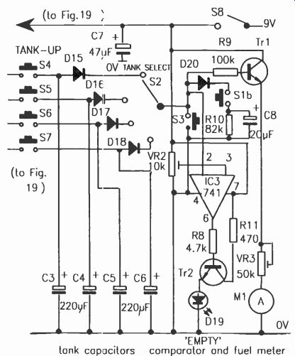
Fig. 20--Circuit diagram for the Pit-Stop fuel-tank and comparator circuit.
As shown in Fig. 20, each player has a tank (electrolytic capacitors C3-C6) that can be charged via a TANK-UP switch (S4-S7). Four of the outputs of the counter are coupled via resistors (R3-R6 on Fig. 19) to the TANK-UP switches. During refueling, when a selected output is frozen for a few seconds, if the relevant TANK-UP switch is pressed, the positive voltage on the output pin is connected via the 47,000-ohm resistor (R9) and switched to charge the driver's tank capacitor. If by misjudgment another driver's LED is selected, then the other driver can press his or her TANK-UP button and take on some fuel.
Before pressing the GO switch S1, the TANK SELECT switch S2 must be set to the player's position. Diodes D15-D18 isolate the tank capacitors and prevent any short-circuiting of charges if the rotary contacts of S2 should make-before-break. Switch S2 connects the comparator (IC3) and fuel meter (M1) to monitor the state of the player's fuel tank capacitor. It also connects the tank capacitor to a discharge circuit, when 51 is pressed, formed by R10 and C8 connected in parallel. On each turn, a player's tank is discharged slightly by this circuit, i.e. fuel is used up on the drive, especially if short distances are selected.
Switch S3, DRAIN TANK, serves two purposes: it can be used with a Hazard Card to simulate a loss of fuel situation, or (at all positions of the TANK SELECT switch) to drain tanks for the next game.
Diodes D 11 to D14 enable tank capacitors to be charged via the TANK-UP pushbuttons if the ALL refuel light is on.
The comparator is a 741 operational amplifier, IC3, which monitors the voltage in a tank capacitor and compares it with a reference voltage set by potentiometer VR2. When the voltage level in the connected tank capacitor falls below the reference voltage, output pin 6 of the comparator goes high; this switches on transistor Tr2 and the
TANK EMPTY LED lights. A TANK-UP operation is then required.
Switch S2 also connects the fuel meter circuit to a driver's tank circuit for monitoring purposes.
Transistor Tr1 is connected as an emitter-follower, the high-input impedance preventing excessive drain on the tank capacitor. The fuel reading on the micro-ammeter (M1) in the emitter circuit is set by the series preset resistor VR3. Leave the setting for VR3 in the maximum resistance position. This will prevent the meter from being dam aged when the game is first turned on.
Construction. The prototype was constructed on a 15-in. square, 3-ply board, layout as shown in Fig. 21, with four 2-in, xxX 1/4-in strips for the sides. The clock generator and decade counter were mounted on a separate piece of 0.1-layout is limited only by your imagination.
in stripboard or perf-board. A perf-board with flea clips may be used or a solderless breadboard and later converted to a matching pre-etched circuit board with components soldered in place.
The wiring is not critical, but neatness is important should troubleshooting be required.
The track layout can be an enlarged replica of the one shown in Fig. 21, or can be modified to incorporate other ideas, especially if the constructor is a motor-racing enthusiast.
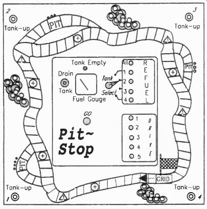
Fig. 21-Suggested Pit-Stop game board layout. The final
Playing. If you drive a car, a quick briefing on the play philosophy is all you will need to under stand the game.
1. Before starting, set the battery switch S8 on and make sure that the four fuel tanks are discharged by pressing the DRAIN TANK switch S3 while rotating the TANK SELECT switch S2.
------------------
PARTS LIST FOR PIT-STOP
Semiconductors
IC1-NE555CP timer
IC2-CD4017 CMOS decade counter/divider
IC3-741 op-amp comparator
Tr1, Tr2-BC109, ECG123A or 2N929, silicon NPN transistor
D1--LED, green (ALL REFUEL)
D2-D5-LED, red (REFUEL)
D6-D10-LEDs, orange (DRIVE)
D11-D18-1N4148 silicon diode
D19-LED, red (EMPTY)
D20-1N4148 silicon diode
Resistors
R1, R7-1,000-ohm R2-100,000-ohm R3-R6-47,000-ohm R8-4,700-ohm R9-100,000-ohm R10-82,000-ohm R11-470-ohm VR1-1,000,000-ohm potentiometer VR2-10,000-ohm trimmer VR3-50,000-ohm trimmer
Capacitors
C1--0.2-µF, metallized polyester
C2-C6-220-µF, 10-WVDC, electrolytic C7-47-µF, 10-WVDC, electrolytic C8-20-µF, 10-WVDC, electrolytic
Additional Parts Materials
M1-Microammeter, 50 or 100 microamperes
S1--2-pole, non-locking, push-button switch
S2-Single-pole, 4-way rotary switch
S3-S7-Non-locking, push-button switch
S8-S.p.s.t., toggle or slide (on/off) switch
---------------------
2. Set the SPEED potentiometer VR1 to an agreed speed.
3. Select in turn to decide order of play by highest drive positions, and which two cars will be in pole (front) positions.
NOTE: Only two cars can be abreast at any time during a race, so a third car coming up fast behind two cars on the same patch of track will have to tuck in behind and forfeit any extra distance selected for the move.
4. The driver in pole position starts by switching the TANK SELECT switch to his position (RED, BLUE, YELLOW or GREEN). For instance, when the RED switch position is selected as shown, the red driver tries to anticipate when the LED for the red output is on and presses GO momentarily to select it. If successful, he then presses his TANK-UP switch to charge up his tank only while the LED remains on. Successful fueling is indicated if the TANK EMPTY lamp goes off, and a driver can select a drive distance when the next turn comes round, or elect to tank-up further.
5. The next driver in pole position, switches the TANK SELECT switch to his position and tanks-up in the same way.
6. The two drivers on the back row of the starting grid follow suit, but cannot drive off until at least one driver in pole position has moved (the no-passing two rule).
NOTE: Holding down the TANK-UP switch after flashing resumes will result in some loss of fuel.
7. At the beginning of a turn, on TANK SELECT, if the TANK EMPTY light is on, a driver must tank-up. Any DRIVE moves selected inadvertently are forfeited.
8. If the ALL position is selected, all drivers can press their TANK-UP button to take on fuel.
Game Cards. Game cards are of two types hazard and advantage. When a car lands on a hazard square (indicated by a triangle) the player draws a Hazard Card and obeys the instructions on the card. Likewise, an Advantage Card is selected whenever a car lands on an advantage square (indicated by a circle). Cut a number of cards to the size of business cards. Leave one side blank and on the other side type or write the following:
Hazard Cards
Oil spill-lose a turn.
Spin off track-lose a turn!
Slow-down for chicane-reduce drive by 1.
Tank holed-press DRAIN TANK.
Aqua-planing-compulsory pit stop to fit wet tires. Lose a turn.
Engine overheating-compulsory pit stop. Lose one turn.
Flat tire-reduce drives by one and one compulsory pit stop.
Advantage Cards
Super-fuel!-add 2 to drive score.
Engine finely tuned-up-add 1 to drive score.
Following wind-double drive score.
Reserve tank-perform TANK-UP.
Double accelerate-hold card until needed.
Close gap-tuck in behind car immediately in front.
Good road-holding-hold card and add 1 to drive score on next bend.
If you wish, let your imagination add additional hazards and advantages to the game cards you make.
The playing pieces for the board game may be pawns from a discarded chess set or some other easily gripped object. Coins are too difficult to manipulate. Paint the playing pieces appropriate colors to reduce confusion. Now then, drivers, man your cars!
------------------
12. Minefields
You are the captain of two ships that must navigate through magnetic minefields, racing against other ships in order to enter your safe port first.
The game can be played by up to four players, each with two ships. In turn, under electronic control, the ships are steered past minefields in the direction of the home port. Refer to Fig. 22 for the board layout. The eight minefields normally flash sequentially (free-run) to warn ships of danger, until a mine is detonated (glows steadily) by a player.
Depending on the players' temperament or the state of the race, some players may take the longer safe channels (unless under other orders), while other captains may risk a winning dash for the home harbor via the minefields.
Movement. Players move in turn by pressing their DETONATE pushbuttons, which freeze the flashing minefield display for a few seconds.
This results in one of two situations, as follows:
1. On detonate, one of the eight mines will glow for a few seconds together with one of the navigation lights. The player will observe which of the navigation lights is on, and also check if there is a ship lying on one of the eight shaded squares that surround the glowing mine. After the player has made his move, any victim in the minefield must either return his ship to base in the case of a direct hit (dark square) or take a NEAR MISS game card (gray square) and act upon instructions.
With regard to the direction of play, Fig. 23 shows the four moves. These are made in relation to a player's starting direction shown next to the DETONATE button:
A green (starboard) light indicates a for ward diagonal turn to the right.
A red (port) light indicates a forward diagonal turn to the left.
AHEAD indicates a forward move directly towards the harbor.
ASTERN indicates a backwards move directly towards the base.
A ship is only moved one square at a time unless a game card instructs otherwise.
Ships cannot be moved sideways.
2. If a mine does not remain on after a DETONATE, then one of the two center LEDs F ACTION STATIONS or NEAR MISS will glow.
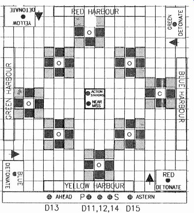
Fig. 22-Minefields game board layout.
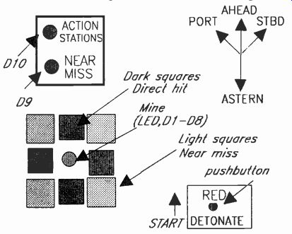
Fig. 23-Details of one minefield and related DETONATE switch and LEDs.
If it is a NEAR MISS light, then the player will take a NEAR MISS game card and act on it. However, in the event of ACTION STATIONS, all players are at liberty to press their DETO NATE button as soon as the display returns to free-run, primarily to ward off any danger or to create havoc. The player will then take a game card from the ACTION STATIONS pile and act on the instructions. Game cards can sometimes be held for future use if not valid. In this case, they will take the place of a turn. After use they will be returned to the bottom of their respective piles.
==========
PARTS LIST FOR MINEFIELDS
Semiconductors
IC1-NE555CP timer chip
IC2-CD4017 CMOS decade counter/divider
D1-D8, D10-Red light-emitting diode
D9, D15-Orange light-emitting diode
D11, D12, D14--Tricolor (green/red) light-emitting diode
D13-Yellow light-emitting diode
Resistors
R1-2,200-ohm
R2-5,600-ohm
R3-100,000-ohm
R4-1,000-ohm VR1-500,000-ohm potentiometer
Capacitors
C1--0.5--uF, metallized polyester
C2-220-µF, 10-WVDC, electrolytic
C3-4.7-µF, 10-WVDC, electrolytic Switches
S1--S.p.s.t. slide or toggle (on/off)
S2-S5--Push-button, non-locking (DETONATE)
Additional Parts & Materials
Shallow box (can be made from plywood), 9V transistor-radio battery, plastic shapes for ships, stripboard or perf board, wire, etc.
===========
The SPEED control (VR1) can be panel-mounted if desired and marked for half-speed and full-speed settings to cater for younger children, and for special instructions, e.g. on ACTION STATION game cards.
Depending on the agreed speed and a certain amount of anticipation, the display can easily be frozen on a desired mine, or navigation direction to shorten a game.
If a move cannot be made for any reason, e.g. obstacles such as coast lines, other ships, mines, then the move is forfeited. A move can be made by either of a player's two ships when thought advantageous, e.g. to hold direction or to avoid a minefield.
Hazards. One of the eight mines can be detonated (permanently lit): by a player's DETONATE switch as a normal turn, by detonating after the ACTION STATION light comes on, or if an ACTION STATION game card says DETONATE.
Any ships in a minefield when it is detonated (one mine permanently on) either take instructions from the top NEAR MISS game card if in the light-shaded square or if a DIRECT HIT is registered (on a dark square) go back to base for repairs.
The HALF SPEED and DETONATE game card introduces an element of skill. It allows more time for a player to anticipate which mine shall be detonated. The player operates the HALF SPEED button to slow down the display before detonating. This gives a chance to inflict a direct hit or a near miss on any rival ships already in a minefield.
Fig. 24--Circuit diagram of the Minefields circuit.
The SPEED control can be reduced for the first few games, or to assist younger players; alternatively, younger players could use the HALF SPEED control for each move.
Ships may not enter an opponent's HARBOR.
Circuit. The 555 timer can be varied by VR1 to give a suitable speed for the free-run display for the mine and navigational LEDs. Refer to Fig. 24. The inclusion of three tricolor LEDs in series with the minefield LEDs gives green (starboard) and red (port) navigation signals. Also, the electrolytic capacitor C2 together with resistor R3 provides a time constant to hold the detonate and navigation information for a few seconds for scrutiny after a DETONATE push-button is released. This time can be lengthened or shortened as desired by altering the value of capacitor C2 (reduce capacitor value to shorten time and vice versa).
Layout is not critical, but requires a minimum of woodworking skill. The circuit elements can be soldered rats-nest style or assembled on pre-etched circuit boards and solderless boards.
Neatness will make troubleshooting easier.
----------------
13. Building the Kapellmeisters
Most transmission-line loudspeaker enclosures involve a lot of tricky woodwork so that many speaker builders with only modest woodworking skills are deterred from building one. With the Kapellmeisters, although quite a lot of wood working is needed, none of it is difficult, mostly it consists of cutting straight edges. These edges must be straight though, so if your saw cuts tend to wander, get the lumber yard to cut them for you. The measurements are uniform with many pieces being identical.
Preparation. Ceramic tiles used in the construction of the Kapellmeisters are standard 8-X-4-inch, cut down to 7 X 4 inches. That is just one straight cut per tile. The exception is the top tile over the speaker which because of its different angle must be narrower, 7 X 3.5 inches.
Triangular wood blocks are used to support the tiles. These are made by first cutting four 3-inch squares, then sawing diagonally to give eight triangles. The two wood 1k blocks for the over-speaker tile are made by halving a 30-X-2-inch rectangle along the diagonal.
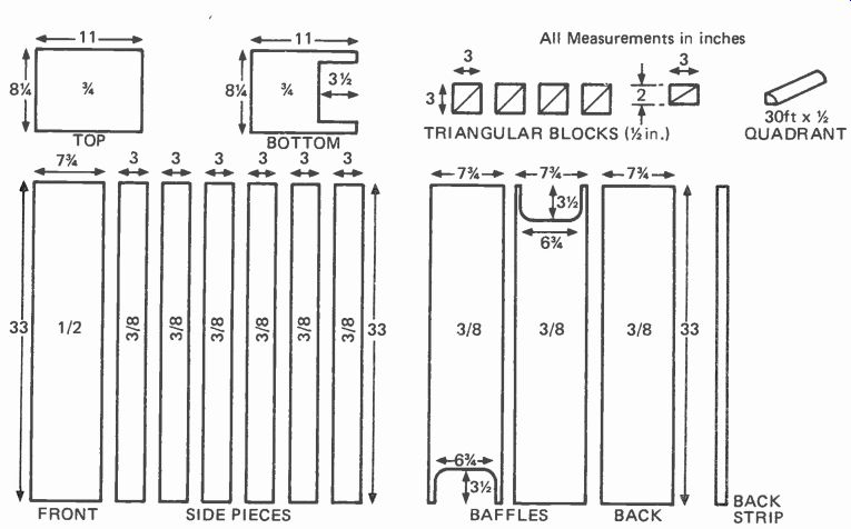
Fig 25--View of all the wooden parts for one speaker cabinet including dimensions.
Each side of the cabinet is made of three parts requiring a total of six side
pieces for one speaker. All pieces should be plywood. See text for addition
details on materials.
A standard 3 X 1 mix of sand and Portland cement (we will call it concrete) is used to fill the space behind the tiles. The concrete is applied between the blocks and the tile bedded on to it.
In all cases screw two or three stout wood flat head screws at random angles into the wood where the cement is to be laid leaving about an inch out of the wood, so that the protruding head of the screw will be buried in the concrete. These screws will then secure the concrete block in place when it is dry. Thoroughly wet the back of the tile before applying it to the concrete. In some cases the front of the tile may need to be held in place while the concrete sets, with wood panel nails knocked into the wooden sides. It does no harm to leave them there afterward.
All jointing is done by a strong wood glue.
Elmer's wood glue was used for the prototypes which is very strong and convenient to apply;
however there are many suitable wood glue alter natives on the market. The glue also fills any small gaps where the saw might have made a slight rough cut. Construction must proceed in numerous stages to allow the glue and concrete to set before continuing with the next stage, so some patience must be exercised. Make both speakers at the same time so that each stage can be completed on both and thus save time.
First Stage. Refer to the diagram of wood panels (Fig. 25), and buy sufficient plywood for all pieces. Remember that these pieces are for one speaker, so each unit will have to be duplicated. As so many are just 3-in. strips, it is likely that much can be obtained as scrap cuts. Most large lumber yards sell these at a reduced rate, and the color or grade doesn't matter as all are concealed except the top and bottom cheeks. The thickness should be as specified, 3/8 inch for the sides, baffles and back, 1/2 inch for the front, and 3/4 inch for the cheeks. It really will save a lot of time and energy if you get the lumberyard to cut the pieces with his machine saw. They usually charge slightly for each cut.
The lumber yard probably will not do the shaped ports at one end of the baffles and bottom cheek, but this can be managed with a fret or cop ping saw. A 7-1/2 X 4-1/4-in. elliptical speaker hole should be cut in the front panel starting 21 inches from the top. Before you cut the hole, check the physical size of the loudspeaker. It may be slightly different. It is desirable though not essential for the hole to be beveled outward.
Loudspeaker. A word about the loudspeaker that you should select. An oval speaker was selected for the original unit and it was rated at 8 watts with pretty good specifications at a low price. You should do the same; however, that would take away the fun of redesigning all project builders get involved with. Keep in mind that as the price goes up, the increase in performance lags behind so that dollars are wasted. Keep in mind that the Kapellmeister is designed to bring the best out of inexpensive loudspeakers.
Second Stage. Start with the front panel; lay it face down supported on some scrap quarter-inch ply or hardboard. Glue the top and bottom edges and fit the top and bottom boards. The front edges of the top and bottom cheeks should not rest on the ply supports but directly on the work surface; they will thus protrude a quarter of an inch beyond the panel. Refer to Fig. 26(a). The top and bottom cheeks should also be positioned to give an equal overlap at either side. The idea is for the top and bottom cheeks to overhang the front, sides and back 1/4-in. from all sides.
Weights should be applied to the free sides of the cheeks to hold them against the panel while drying. Measure the distance between the rear edges of the top and bottom cheeks to ensure that it-is exactly 33 inches and therefore the top and bottom are parallel. Wait for glue to set and hard en.
Third Stage. Fit the first pair of side pieces, gluing the ends and the edge contacting the back of the front panel; ensure the pieces are flush with the edge of the front panel. Measure across the upper edges to make sure they are 7-3/4 inches and so are true. Now glue the triangular blocks in place at the bottom and top as shown in (a) of Fig. 26, the top ones being the special sized ones.
Glue the edges as well as the face that contacts the sides, but be careful in pressing them into place that you do not move the sides. Wait for the glue to set.
Fourth Stage. Now fit the speaker, screwing it in place over the aperture, and connect by soldering a pair of wires which are run down the panel to a hole drilled in the bottom. Leave a few inches of free wire outside the cabinet, and make sure both speakers are connected the same way to the color-coded wire. After the wires are installed, fill the drilled hole for the wires with a mixture of saw dust and wood glue to seal the hole airtight and secure the wire in place.
It is prudent to cover the front of the speaker with a piece of stiff cardboard secured by masking tape or staples to protect the cone from accidental damage.
Fit several screws to the bottom and top cheeks between the triangular blocks, leaving about an inch protruding at different angles.
These will be embedded in the concrete when it is applied and so will hold the resulting concrete wedge in place. Next fill the space between the bottom blocks with cement (not too wet) and bed the trimmed tile onto it. Place the top narrow tile on the blocks and fill in behind it with cement.
Fifth Stage. Saw suitable lengths of 1-2-inch round molding (quadrant) and glue into the corners between the front panel and the sides. If they are warped they should be held in place with panel nails. Glue two additional strips of 1-2-inch round molding at the top inside edge of the sides and nail in place.
Cut three lengths of 1-inch thick acoustical wadding to size and lay them in the cabinet so that two start at the bottom of the speaker, and the third lies over it to the top of the case. (You can substitute roof/wall glass-foam 3-1/2-in. insulation for the acoustical wadding. Remove the insulation from its paper backing.) Fill the space above the speaker with a rolled up piece of wadding. Do not compress the wadding. Make the lengths a few inches longer so that they bend up at the bottom over the tile. Drops of wood glue or any quick-drying cement will hold the wadding in place.
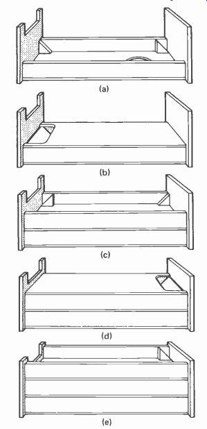
Fig. 26--The vies a through e show the assembly procedure for
the Kapellmeister. (a) First stage in construction. The front is glued to the
top and bottom cheeks., using 1/4-in. supports to lift front panel to correct
position. First pair of side pieces fit ted and triangular blocks (small ones
at the top) in position. Then apply concrete, fit tiles and lay wadding. (b)
Fix in place first baffle, gluing down to insure close fit. (c) Fit second
pair of side pieces and four triangular blocks (all blocks installed here after
are regular size). Install tiles, concrete and wadding. Tuck extra lengths
of wading through aperture into first channel. (d) Fit second baffle in place.
Aperture goes at the top. (e) Glue in third pair of sides and last pair of
triangular blocks. Fit tile and concrete and install wadding with extra length
going into the aperture. Install the back panel (not shown). Refer to text
for complete details.
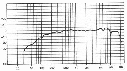
Fig. 27-Curve of the Kapellmeister speaker system frequency response. Some
bass boost by the amplifier will straighten the curve at the low end.
Now fit the first baffle with the cut-out at the bottom, gluing to the top edge of both the sides and the upper 1/2-inch round molding surface.
Also glue to the top and bottom cheeks. Secure with wood panel nails to ensure a close fit as (b) in Fig. 26. Next, fit the second pair of side pieces and two pairs of blocks top and bottom, (see c).
Fit 1/2-inch round molding to corners as with the first channel, also to top edges of the sides; wait for all the glue to dry.
Sixth Stage. Fit the tiles and cement as with the first pair, not forgetting to use concrete-securing screws to top and bottom cheeks in the area to be filled with concrete. This time the top one will be bedded and the bottom one rear-filled.
Wait for the concrete to set.
Seventh Stage. Cut two pieces of acoustical wadding about 18-inches long and push half the length of each up the lower channel through the cut-out, and lay the other half length back along the top channel. Now lay three full length strips over these along the complete upper channel.
This gives the extra density at the first bend needed to dampen the third-harmonic antinode.
Next comes the second baffle which is glued and nailed as the first but with its cut-out at the top as shown at (d). Fit the third and final pair of sides, also the last pair of blocks plus the 1/2-inch round molding in the corners and top edges, see (e). Allow glue to harden, Eighth Stage. Now for the last tile, again not forgetting the screws in the top to secure the concrete wedge. Mount the tile on the blocks using wood-panel nails to keep it in place; this will be easier if the enclosure is stood vertically upside down. Return to the assembly to the horizontal, and fill in rear with cement. Wait until set.
Ninth Stage. Lay three strips of wadding in the channel making sure the bend is filled. Put some extra here if necessary to fill completely.
Cut another strip about 24-inches long and tuck half the length under the other three at the outlet, and bring it over the top so that it covers the rough ends. Lastly glue and nail the back in place.
Tenth Stage. Now for the finishing. Sand down any ridges in the sides, but do not be too fussy, for they will be completely covered with fabric. You could cover the multi-joined sides with a wood veneer, but it is not mandatory.
Check carefully for any cracks or crevices in the jointing and fill with the wood glue. Sand, then stain or varnish the top cheek and the edges of the bottom one; there is no need to do underneath unless you are fussy. Paint the body with flat black paint including the inside rim of the loudspeaker aperture, but be very careful not to get any paint on the loudspeaker cone as this would affect its flexibility. The painting ensures that the bare wood does not show through the grille fabric with which the whole body excluding the cheeks is covered.
The two back strips (one for each speaker) should now be cut to fit exactly between the top and bottom cheek rear overhangs. These strips conceal the join in the fabric covering so should be about one-inch wide preferably beveled at both edges to give a good finish. They should be stained or varnished the same color as the cheeks.
Eleventh Stage. Obtain sufficient black speaker grille fabric to cover both speakers. Any other color can of course be used if preferred and s obtainable.
Cut the fabric to the exact size to cover the body between the cheek overhangs, but leave a flap 4 inches longer and 8-inches wide, at the start. Secure the vertical starting edge at one edge of the back of the enclosure with tacks so that the flap hangs over the bottom. Then pull it around, keeping it taut, overlapping the start and securing it with one of the wooden strips down the middle of the back. This can be done with brass counter sunk screws with cupped washers which give a professional-looking effect.
Next trim the flap to fit between the prongs of the bottom and fix it across the exit port with staples.
Twelfth Stage. Make or purchase two sets of 2-inch high, wood legs. A single rear one should be made to incline backward under the rear exit vent to give greater stability. They can be stained or varnished to match the rest. The Kapellmeisters are now complete and ready to go into action.
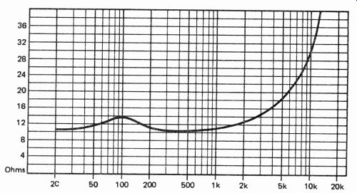
Fig. 28--The Kapelimeister's impedance curve which is typical of projects
using quality loudspeakers.
Performance. As an anechoic room was not available to test the Kapellmeisters, frequency response tests were made with the multiple microphone-position technique. The test was repeated on the second speaker, and the results were very close, so the plot in Fig. 27 can be considered fairly accurate.
Surprisingly, the treble response is sustained beyond 16 kHz and actually continues up to 20 kHz, a remarkable achievement for a single-driver speaker with no tweeter. This is a tribute to the controlled flexure of the cone and the effectiveness of the high-frequency folded horn inside the cabinet. The undulations are fairly smooth, and some of the vicious peaks and dips encountered with certain multi-driver speakers are notably absent. The response is within 5 dB from 16 kHz to 200 Hz, apart from small deviations at 7 kHz and 10 kHz. There are no phase problems over any part of the range.
Of course the performance varies from loud speaker type to speaker type, but when you start with a known-good loudspeaker the results will be good.
As expected, the bass is not sustained with a flat response to as low a frequency as would be obtained from a large infinite baffle or reflex enclosure. The response crosses the-5 dB level at 200 Hz and from there a very gentle descent, but audible output is maintained down to around 36 Hz. Actually, there is a 3-dB drop in the octave 500 to 250 Hz, a 6-dB drop from 250 to 125 Hz, and a 12-dB drop from 125 to 62 Hz and below.
This gentle and gradually increasing slope results in a more natural and musical bass than when the roll-off is lower, but steeper. A further advantage is that this curve is ideal for applying a little bass boost at the amplifier. All bass boost controls hinge the response curve upward from a pivotal point at 1000 Hz. Frequencies just below 1000 Hz are hardly affected, but the amount of boost increases as the frequency drops. If bass is boosted with speakers having a steep roll-off, the frequencies just above the roll-off point are lifted to produce a hump, so resulting in a boomy effect. Here, bass boost will lift the curve to give a flatter response without boom.
Thus with a little boost in the bass, the single-driver loudspeaker in an enclosure only 8-inches wide can be made to give a response equivalent to that of a much larger multi-driver speaker, but without the phasing problems and distortions they and the crossover network produce.
The impedance curve is also of interest and is here shown (Fig. 28). There is no large peak in the bass, just a small rise at 100 Hz, which is at the third harmonic of the transmission line resonant frequency.
Bass peaks indicate a high back emf generated by a large cone movement at the resonant frequency, even though the acoustic output may be damped by the cabinet design. Often these excursions may be large enough to enter the non-linear region or even strain the cone suspension. In such cases bass boost should be applied cautiously and moderately if at all to avoid speaker damage, quite apart from causing a hump in the response as noted above. Here, having no impedance peak, there is no excessive cone excursion at any frequency and no such restraint is necessary. Bass boost can thus be applied to obtain a satisfactory balance without fear of damage, providing the speaker's power rating is not exceeded.
At the high-frequency end, the impedance curve gradually rises to 60 ohms at 20 kHz. This is not due to increasing cone movement but the increase of the coil reactance with frequency.
This means that less power is being taken from the amplifier at these frequencies. As amplifier distortion often decreases with an increase of load impedance, this should present a very easy load for any amplifier, and there should be none of the unexpected problems often encountered when an amplifier takes a dislike to a particular speaker. Nowhere does the impedance fall below 10 ohms.
An amplifier of just a few watts may be used for full listening impact in a listening room. Five watts per channel should be sufficient and well within the, speaker's 8-watts rating. You can go the full power rating for a larger listening room.
The efficiency afforded by the Kapellmeisters allows the opportunity to use a class A amplifier which can easily be designed for low powers such as these.
-----------------
14. Window Helix Antenna
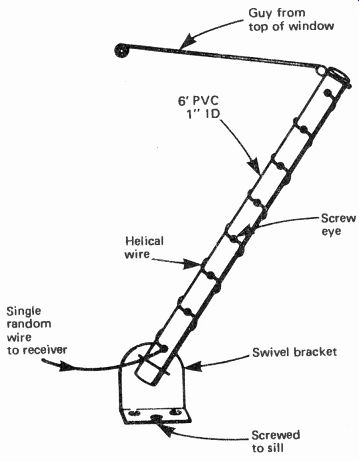
Fig. 29--Construction details for the Window Helix antenna.
A low-cost and effective window-mount vertical antenna can be constructed from insulated hook up wire and PVC (polyvinyl chloride) piping (Fig. 29). A 5- or 6-foot length of 1-inch PVC piping will do well. If you have a tall window you may be able to use a longer length with a secure attachment. A swivel mounting bracket which is attached to the window sill will permit you to tilt the vertical outward away from the window. When you do so be certain to use a guy arrangement at the top of the window (or even a long bracket) to prevent whipping in the wind.
Good performance on the 11- to 19-meter bands is obtained using a helical-wire length of approximately 15.5 feet which is laced through screw eyes turned into the PVC piping. Space the screw eyes to accommodate the overall length of wire you plan to use. In place of screw eyes, you may want to cement the wire to the pipe using the glue commonly used to cement PVC pipes together.
A 15.5-foot wire length also resulted in acceptable performance on the 22- to 31-meter bands as well. A random-wire feed was used permitting the position of the helical wire and the wire connecting from the base to the receiver to act as a long-wire so as to improve performance on the lower frequency shortwave bands. A tuner is helpful, though by no means mandatory.
Coaxial feed can also be used. When doing so, connect the outer braid to the swivel bracket.
If you live in an apartment complex where the management objects to window antennas, paint the pipe black so it will be less noticeable and attach a national flag to it. It would be un American or un-Canadian to ask you to take it down, especially if you first raise the flag on a national holiday.
-------------------------------
15. Inverted V Antenna
It may not appear so, but the Inverted V Antenna is really a modified version of the half-wave dipole. Looking at Fig. 30, it should be obvious relationship to the dipole antenna.
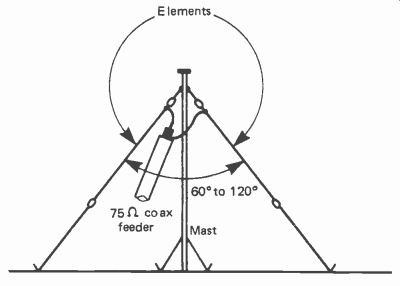
Fig. 30--The arrangement used for the Inverted V Antenna.
The length of one element of the "V" are given in the table.
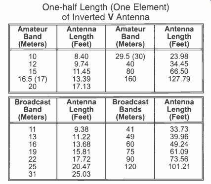
--------- One-half Length (One Element) of Inverted V Antenna
The Inverted V Antenna configuration has similar characteristics to a half-wave dipole and has the obvious advantage of needing only one mast or other central support. Although at first sight it may appear to need less space than a half-wave dipole this is not necessarily the case. The elements are slightly longer than for a half wave dipole, and in order to keep the elements well above ground level it is either necessary to have a tall mast (especially for an antennas cut for a low frequency band) or keep the angle between the elements quite large and have very long sup porting lines. Angles of the Inverted V are typically 60 to 120 degrees. This type of antenna is probably most suitable for use in situations where suitable supports for the antennas are already available or are easily improvised. For example, antennas of this type are often installed over the roof of a house (but must be kept reason ably well clear of the roof in order to obtain good results).
The length of an Inverted V Antenna in feet is equal to 486 divided by the frequency in mega hertz, or in meters it is equal to 148 divided by the frequency in megahertz. This is the total length of the two elements, and must be halved to give the length of each element.
The lists provided below give the element lengths (not the overall lengths) for Inverted V antennas for use on the shortwave, amateur and broadcast bands.
-------------------------
16. Audible Timer
This easy-to-build-timer circuit can be set for any period of minutes, from 1 minute to 7 minutes. A rotary switch is used to select the timing period.
The position to which the switch is set is indicated by numerals marked on the panel. A push button resets the circuit and timing begins from the instant the button is released. At the end of the period there is a loud audible signal from the speaker. This is an intermittent note for maximum impact against a noisy background. The note continues for 1 minute. As well as the sound signal there is a high-intensity LED which comes on during the timing period and flashes when the period ends.
One of the advantages of this timer is that it can be set and run in the dark. This makes it suit able for dark-room timing. It is also ideal as a timer for use by blind or deaf persons.
How It Works. The Audible Timer relies on the principle of obtaining a relatively long timing period by dividing down the frequency of a high-frequency astable multivibrator. The chip used for the multivibrator is the well-known 555 timer in its CMOS form (Fig. 31). The frequency is independent of variations in the level of the sup ply voltage, so the circuit is ideal for battery operation. The preset resistor VR1 allows the frequency to be set to 273 Hz. This provides the alarm tone. The 273 Hz signal is divided by the 14-stage counter IC2. At pin 8 of the counter we obtain a signal at approximately 1 Hz which is used to make the note intermittent. The timing frequency comes from pin 14 of the IC, at which the astable frequency is divided by 214, or 16384, giving a frequency of 1/60 Hz, or 1 count per minute.
The output from pin 14 is inverted by transistor TR1 and fed to the clock input of a second counter IC3. This is a decade counter with decoded outputs. The outputs of this counter are normally at logical high, except that just one of the outputs is low at each stage of counting. When the counter is reset, output 0 goes high. On the next positive-going clock input, output 0 goes low and output 1 goes high. At each successive high-going clock input the outputs go high in turn from 0 to 7, repeating. The rotary switch S3 selects which of the outputs is to be used to indicate the termination of the timing period.
The circuit is reset by pressing button S2, which resets both counters and also the flip-flop formed by gates IC4a and IC4d. All outputs of IC2 go low. All outputs of IC3 go low, except for output 0, which goes high. Output 0 is not used in the circuit. A low output from one of the other pins of IC3 makes the output of the flip-flop (IC4 pin 3) go high. The output of IC4c goes low. This turns off the npn transistor TR2, which drives the loudspeaker, but turns on the pnp transistor TR3, causing the LED to light.
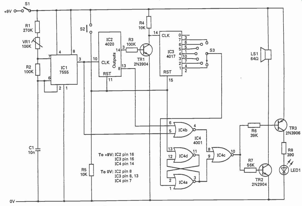
Fig. 31--Circuit diagram for the Audible Timer.
============
PARTS LIST FOR THE AUDIBLE TIMER
Semiconductors
IC1-7555 timer IC2-4020 counter chip IC3-4017 counter/divider, 10-line output chip IC1 1001 quad 2-input LED1-Light-emitting-diode, high-intensity red TR1-2N3904 transistor, npn TR2-2N2904 transistor, npn TR3-2N3906 transistor, pnp
Resistors
R1-270,000-ohm, metal-film
R2-100,000-ohm, metal-film
R3-100,000-ohm
R4, R5-10,000-ohm
R6-39,000-ohm
R7-56,000-ohm
R8-390-ohm
VR1-100,000-ohm linear-taper potentiometer
Additional Parts & Materials
C1-1-nF, polystyrene capacitor
LS1-Loudspeaker, sub-miniature, 1.5-in. dia., 64-ohm
S1--Switch, s.p.s.t. (on/off), toggle or slide
S2--Switch, push-button, non –locking
S3-Switch, rotary, 7 positions minimum 9-volt transistor-radio battery, battery connector, plastic case, wire, pert-board, solder.
===========
While the reset button is held, the output from IC2 pin 3 is low, turning off TR1. This means that the input to IC3 pin 14 is high. Counting begins when S2 is released. After 30 seconds, IC2 pin 3 goes high, and the input to IC3 goes low, but this has no effect on IC3. After 1 minute IC2 pin 3 goes low, and the input to IC3 goes high, causing this counter to advance one count. Its output 1 goes high. The counter is incremented every minute until the output selected by S3 goes high.
The high level from the selected output sets the flip-flop. IC4 pin 3 goes low. This makes pin 9 low, allowing the signal reaching IC4c from IC4b to pass through to TR2 and TR3. This signal consists of the logical NOR of the astable signal (273 Hz) and the signal from output 8 of IC2 (1 Hz). The result is a note at 273 Hz, pulsing at the rate of 1 Hz. This is heard from the loud speaker. The LED flashes on at the same time.
Since the mark-space ratio of the astable output is high, the LED is turned on at almost full brightness during the on periods.
Construction. This circuit requires only a small current and is powered from a 9-volt transistor radio battery. Assuming that a small (1.5-in. diameter) loudspeaker is used, it can be housed in a small plastic case with the circuit.
The parts can be assembled on a perf-board or some other pre-drilled board with holes on a 0.1-in grid. For stability of timing, and minimum effect of temperature, use metal-film resistors for R1 and R2 and a polystyrene capacitor for C1.
Assemble the astable circuit and the first counter (IC1 and IC2). Check that all outputs of IC2 go low when S2 is pressed. When S2 is released, a voltmeter shows that the output at pin 13 is approximately 1 Hz and that pin 3 changes from high to low or low to high every 30 seconds.
Adjust VR1 to obtain this timing. While the remainder of the circuit is being built, it is convenient to use the output from IC2 pin 1 to drive TR1. The signal there runs at 1/15 Hz thus saving prolonged periods of waiting while testing the circuit.
Wire up TR1 and IC3, and test their operation, then complete and test the remainder of the circuit.
---------------------
17. Long-Interval Alarm Timer
The Long-Interval Alarm Timer is capable of timing intervals of hours or even days. The maximum interval is two weeks. The timer sounds an alarm when the selected interval has elapsed. In addition, it sounds a different alarm if any attempt is made to turn it off before the end of the interval. In this way the unit can convey two messages: "Interval still in progress!", and "Interval finished!". While it is timing, the unit uses very little current (2.5 mA) so it is suitable for battery operation over prolonged periods.
The circuit was intended as a pill-box reminder, though it has other applications. If you have to take pills regularly, it is all too easy to forget exactly when the next dose is due.
Conversely, it is easy to forget that a dose has been taken only recently and taking a second dose too soon could have undesirable effects, if nothing less than wasting money on expensive medicine.
The Long-Interval Alarm Timer can not pre vent a person taking out too many pills when the pill-box is opened, neither can it make sure that the person actually swallows the pills removed, but, with intelligent use, it is a helpful personal prompter.
Pill Box. The circuit is housed in a small box serving as the pill-box. A micro-switch activated by the lid of the box lets the circuit know when the box is opened. The warnings are given by an audible sounder and by a pair of flashing LEDs.
Shutting the box (presumably after having taken a pill) starts the long-period timer; both LEDs are out and there is no alarm sound. If the box is opened before the next time that a dose is due, an urgent high-pitched alarm sounds, bleeping rapidly, and the red LED flashes. This warns the person that it is not yet time for a pill. The person shuts the box, the sounder and LED cease their activity, and timing continues unaffected by the action of opening the box. When a dose is due, a slower, deeper bleeping note is heard and a green LED flashes. This continues until the box is opened.
Fig. 32--Circuit diagram for the Long-Interval Alarm Timer.
==========
PARTS LIST FOR LONG-INTERVAL ALARM TIMER
Semiconductors
D1-Light-emitting diode, red (see text)
D2-Light-emitting diode, green (see text)
IC1-4011 2-input NAND chip
IC2-4001 2-input NOR chip
IC3-7240 CMOS programmable timer chip
IC4-4060 14-stage counter with oscillator chip
IC5-4023 3-input NAND chip
TR1-ZTX300. SK3854 or ECG123AP.
TR2, Tr3--MPSA13 high-gain Darlington
Resistors
R1. R2, R6-10,000 –ohm
R3-See text to determine value
R4-180,000 –ohm
R5-47.000 –ohm
R7-470 –ohm
R8--120,000-ohm
R9-12.000-ohm
R10, R11-56,000–ohm
R11-56.000-ohm
VR1--(See text)
Capacitors
C1, C2--(See text) C4-1-nF
Additional Parts & Materials
B1-Battery consisting of 4 AA alkaline cells and holder
LS1-Loudspeaker, 1.5-in. dia, 64-ohms (approximately)
S1-Microswitch. normally-open (See text)
S2-Rotary switch, miniature, non-shorting. 6 (or more) positions
Plastic case, 4- x 2.5-in. circuit board builder fabricates. knob, wire. solder, etc.
===========
The LEDs are of different shape, the red one being triangular to reinforce the warning message. The difference of shape avoids the risk of confusion by color-blind persons.
How It Works. This project is based on the 7240 CMOS programmable timer chip (IC3), which has an accuracy of 0.5%. It contains a time-base generator, the frequency of which is decided by a resistor and capacitor (R3NR I and C2 in Fig. 32). The basic time period is RC seconds; so, given that the maximum value of R is 10 Megohms and the maximum value of C is 1000-11F , the maximum time period is 10,000 seconds, or 2.8 hours. IC3 also has an 8-stage binary-divider chain. The total period available is 27 times the above, which is just over 14 days.
But, as explained below, there may be practical problems in obtaining the very longest periods.
In Fig. 32, Si is an optional power switch. S2 is the switch which is closed to initiate timing. In the pill-box application, this could be a microswitch, mounted so that it is closed when the lid of the pill-box is closed. Closing S2 generates a brief low pulse which goes to pin 11 of the timer IC3 and starts the timing. The output of the timer is normally high, but goes low for the whole of the timing interval. The length of the interval is selected by a rotary switch S3. If you have a dedicated version planned for the timer project, you could hard-wire the switch out of the circuit.
Pins 1 to 8 of IC3 are the outputs from the 8 stage divider chain. When the counter is reset they all go high, while timing they go through an inverted binary sequence. Thus pin 1 goes low after the basic time period, while pin 4, for example, goes low after 8 times the basic period. R5 connects the output to the reset terminal (pin 10) so that the counter is reset at the end of the inter val. Figure 32 shows only 6 outputs being used; this is sufficient for the pill-box application, but there is no reason why all 8 outputs or any combination of fewer outputs should not be selected.
For a single-period timer, omit S3 and wire the chosen output directly to the junction between R5 and R6.
The first stage of the logic consists of two NOR gates and a NAND gate wired as an inverter (part of IC1, 4001). These gates detect the two alarm states. Gate IC2a goes high (at pin 3) when S2 is open (box open) and the IC3 is timing (output low). This is the state of opening the box while the timing interval is in progress. Gate IC2b goes high (at pin 4) when S2 is closed and the output of IC3 is high. This is the state after the end of the interval if the box remains unopened.
A high output on either pin 8 or pin 9 causes a low output from Gate IC2c (pin 10). This makes the reset input of IC4 low. IC4 is a 14-stage counter with its own oscillator, which begins to oscillate when the reset is made low. The oscillator has a period of about 25 kHz, which is divided down to produce 1.6 kHz at pin 7 (high-pitched note), 200 Hz at pin 6 (low-pitched note), 6 Hz at pin 1 (fast bleeping), and 1.5 Hz at pin 3 (slow bleeping). The remainder of the logic consists of gates producing the fast high-pitched bleep signal, which goes to the red LED (D1) by way of transistor TR2, and the slower low pitched bleep, which goes to the green LED (D2) by way of TR3. Both signals go to the speaker LS1 by way of TR1.
Putting It Together. The project is built on a board only 4 in. (10 cm) by 2.5 in. (6.5 cm). With a miniature loudspeaker, 1.5 in. (38 mm) in diameter, the unit is housed in a reasonably small plastic box. Since it requires only 2.5 mA, the timer runs for about a month on a set of four AA alkaline cells. There are only 3 logic gate ICs, IC1 (2 input NAND, 4011), IC2 (2-input NOR, 4001) and IC5 (3-input NAND, 4023) and all gates are used. The gates belonging to these three ICs are scattered in ones and twos all over the circuit diagram but can easily be identified by their symbols.
Begin with the trigger circuit IC1a/IC2d and timer 1C3, and their associated resistors and capacitors. For use as a pillbox timer, with a maximum interval of 8 hours (IC3, pin 8) values for the timing components are R3 = 3.3 Megohm, VR1 = 2.2 Megohm and C3 = 47 RF . Use a tantalum capacitor for C3. The tolerance of these is ±20%, but VR1 allows timing to be adjusted to accommodate this.
The main problem with tantalum and aluminum electrolytic capacitors is that they have an appreciable leakage current. The effect of this is that charging times tend to be longer than those calculated by multiplying R and C together. As a rule, tantalum capacitors have lower leakage than aluminum electrolytic capacitors. The most commonly available types have a leakage of 0.02 RA per volt per RF , with a minimum leakage of 1 RA. Low-leakage types are available with half this leakage, though such types are not widely stocked. The leakage quoted above is for a capacitor operating at its maximum working voltage; leakage is markedly reduced when operated at a lower voltage. The voltage across the capacitor in this project ranges from 1.6 to 4.2 volt, but the working voltage is likely to be 16 WVDC or even 20 WVDC for a 47-RF capacitor. This helps to keep leakage to an acceptable level. Using a 47 uF tantalum capacitor with resistances totaling 5 megohms or more is feasible. If really long intervals are required, make the resistor slightly less than the calculated value.
Having settled on a suitable value for R3, adjust VR1 until an interval of 225 seconds is obtained with S3 switched to the calibration position, position 1. This gives intervals of 8 hours, 4 hours, 2 hours , 1 hour and 30 minutes from pins 8 to 4. Other values of R3 and C3 may be substituted for other applications.
Next assemble the oscillator circuit, IC4 with resistors and capacitor. A voltmeter monitoring the output at pin 14 confirms that this works correctly when pin 12 is made low. Assemble the rest of the logic and check that the outputs at IC1 pins 4 and 10 and IC5 pin 10 behave as described earlier. Finally, add the transistor switches. TR2 and TR3 are shown in the schematic diagram as single NPN transistors, but the MPSA13 is a high-gain Darlington transistor. High-intensity LEDs are preferred but a red triangular one of normal intensity may be used for D1.
-------------------
18 Twangy Distortion
Unit A conventional distortion unit has a major effect on the processed signal. Apart from adding distortion products, it also changes the input signal's envelope. In other words, it alters the way in which the volume of each note varies. Normally the output from a guitar-string pluck has a high initial level, but it rapidly falls away to a much lower level, and then decays at a more gradual rate. The envelope of a signal is the all-important parameter that governs its precise character and sound. In the case of a guitar it is the fast attack and quite rapid initial decay that gives the characteristic "twangy" guitar sound.
============
PARTS LIST FOR TWANGY DISTORTION UNIT
Semiconductors
IC1-NE5532N, very low-noise, dual-operational amplifier
IC2-LM13700N or LM13600N, very low-noise, dual-operational amplifier
IC3-LF351N JFET wide-band operational amplifier
D1-D8-0A91 diode
Resistors
R1, R2, R14-100,000-ohm
R3-1,000-ohm
R4, R10-10,000-ohm
R5, R6, R17-3,900-ohm
R7, R8-470-ohm
R9, R11, R13-18,000-ohm
R12-270,000-ohm
R15-27,000-ohm
R16-33,000-ohm
VR1-100,000-ohm, linear-taper, carbon
VR2-4,700-ohm, miniature, trimmer
VR3-470,000-ohm, miniature, trimmer
Capacitors
C1--10-nF ceramic
C2--1-µF, 50-WVDC, electrolytic
C3--22-µF , 16-WVDC, electrolytic
C4--470-uF , 10-WVDC, electrolytic
C5--10-µF , 25-WVDC, electrolytic
C6, C7--2.2-µF , 50-WVDC, electrolytic
C8--1-uF , 50-WVDC, electrolytic
C9--4.7-µF , 50-WVDC, electrolytic
Additional Parts & Materials
B1-9-volt, transistor-radio battery and clip connector
JK1, JK2--Audio jack (select to match audio system cables)
S1--S.p.s.t., miniature, toggle switch
S2--S.p.s.t., push-button, locking switch 8–pin
IC socket (2 required), 16-pin IC socket, control knob, aluminum case, circuit board, wire, solder, etc.
============
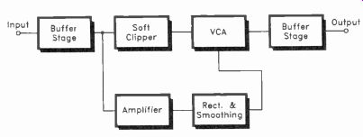
Fig. 33--Block diagram for the Twangy Distortion Unit.
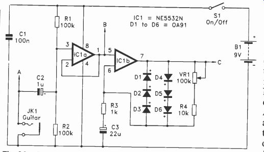
Fig. 34--Circuit diagram for the Input buffer and clipping amplifier stages
of the Twangy Distortion Unit.
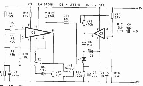
Fig. 35--The circuit for the voltage-controlled amplifier and rectifier stages
the Twangy Distortion Unit.
Clipping the signal from a guitar tends to give an output signal of uniform amplitude right up to the point where the input signal decays away to practically nothing. The fast attack of the input signal is retained, but the rapid fall in amplitude immediately after the attack period is not. This gives a sound which is largely twang free! Even with soft clipping, the amount of compression applied to the input signal is such that the original envelope of the signal is largely lost.
It is possible to produce a distortion unit that retains the original envelope of the input signal, or something close to it. It requires a rather more complex circuit than an ordinary distortion unit, but our Twangy Distortion Unit is reasonably simple and inexpensive to build.
Signal Flow. The block diagram of Fig. 33 shows the arrangement used in the Twangy Distortion Unit. The input signal is applied to a buffer stage, and the signal is then split two ways.
The main route is via a soft clipping amplifier, or a hard clipping amplifier can be used here if preferred. The distorted and compressed output signal from the clipping circuit is fed to a voltage-controlled amplifier (VCA), and then to the output via a buffer amplifier. The amplitude of the output signal is governed by the control voltage fed to the VCA.
The higher the control voltage to the VCA, the higher the amplitude of the output signal. By feeding the VCA with a suitable control voltage, the output signal can be molded into the required envelope shape.
The control voltage is produced by a side chain which first amplifies the input signal from the buffer stage. The amplified signal is fed to a rectifier and smoothing circuit. This produces a DC output voltage that is 3k9 roughly proportional to the amplitude of the input signal. Via the
VCA, this DC voltage modulates the output signal to give an output envelope shape that is reasonably close to the envelope shape of the input signal. The output envelope is not identical to the input envelope because a few small errors occur in the amplitude control circuits. However, the match is close enough to give the required twangy sound.
The Circuit. Figure 34 shows the circuit for the input buffer and clipping amplifier stages.
The circuit for the VCA and other stages is shown in Fig. 35. Taking Fig. 34 first, the clip ping amplifier is based on chip IC lb. If hard distortion is required, simply replace D1 to D6 with a pair of 1N4148 silicon diodes, one diode for each string of three (D1-D3 and D4-D6) connected as in Fig.34; IC1a acts as the input buffer amplifier, and this is a simple non-inverting type which provides an input impedance of 50,000 ohms. IC1 is an NE5532N, which is a very low-noise dual operational amplifier.
A transconductance operational amplifier (IC2) is used as the basis of the VCA. Although this is a form of operational amplifier, apart from differential inputs it has little in common with ordinary operational amplifiers such as the 741C and LF351N. A transconductance amplifier is current rather than voltage operated. The output current is controlled by the differential input current. In practical circuits, including the present one, series resistors at the inputs plus a load resistor at the output effectively convert the device to a form of voltage operation. R10 is the resistor in series with the input signal, and R9 is the output load resistor. C4 plus R5 to R8 are used to provide biasing to the inputs of IC2, and they also provide a center-tap on the supply lines which is used as a sort of central ground bus for the output load resistor. Unlike ordinary, operational amplifiers, transconductance amplifiers are often used "open loop". IC2 is certainly used in this manner, and it therefore lacks any form of negative feed back circuit.
Chip IC2 has a built-in emitter-follower buffer stage which can be connected at the output of the transconductance amplifier. VR2 is the load resistor for this stage, and it also acts as a variable output attenuator. This enables the output level of the circuit to be matched to the direct signal from the guitar.
A transconductance amplifier has an extra input, and it is this extra input that makes these components so useful in voltage-controlled filters and amplifiers. The output current is governed by the differential input current and the current fed to the control input. In effect, the gain of the amplifier is controlled by the current fed to the control input. In this case R13 is connected in series with the control input, so that it is voltage rather than current control that is obtained. R12 provides a small bias current to the control input under quiescent conditions. Without R12 there is a tendency for the output signal to decay a little too fast. Also, when the VCA provides very high attenuation levels the output signal seems to become heavily distorted, and produced a rather unmusical "buzzing" sound. R12 completely eliminates both problems.
The transconductance amplifier in the LM13700N has a fourth input, and this can be used to supply a bias current to linearizing diodes at the input of the amplifier. This enables higher signal levels to be handled. In this circuit R10 provides the bias current to the linearizing diodes. The LM13700N used for IC2 is actually a dual transconductance amplifier and buffer amplifier, but in this circuit only one amplifier and buffer stage are utilized. No connections are made to the other amplifier and buffer stage.
Note that the LM13600N is virtually identical to the LM13700N, and will work just as well in this circuit.
Chip IC3 is used in the amplifier which drives the smoothing and rectifier circuit. This is an inverting amplifier which has its closed-loop voltage gain controlled by VR3. The maximum voltage gain is about 120 times, and this is obtained with VR3 at maximum resistance. The wide range of gains available should enable good results to be obtained using most guitar pick-up.
The rectifier and smoothing circuit is a simple half-wave type based on D7 and D8. Germanium diodes are used for D7 and D8 because they have lower forward voltage drops than silicon types, and they therefore give a DC output voltage which is a more accurate reflection of the input signal's amplitude. The attack and decay times of the smoothing circuit are kept quite short so that the output envelope accurately follows the envelope of the input signal. On the other hand, the decay time is made sufficiently long to avoid unwanted distortion products on the output signal.
The current consumption of the circuit is about 8 milliamps. This can be supplied by a 9-volt transistor radio battery, but it would be more economic to use a higher capacity battery (six AA cells or larger in a holder) if the unit is likely to receive a lot of use.
Adjustment. Adjust VR1 to give the best distortion effect. It is advisable to use the lowest resistance that gives good results, as higher resistances will give greater voltage gain, which will in turn encourage problems with feedback and general electrical noise. VR3 should be adjusted before giving VR2 its final setting. Adjusting VR3 is again just a matter of finding the setting that gives what is judged to be the best effect.
Setting VR3 too low in value will result in rather a low-output level, and generally unimpressive results. Using a value that is too high will give plenty of output signal, but the initial part of the output envelope might be compressed slightly.
This will give an output that is slightly lacking in terms of "twangyness." In between these two extremes there should be a fairly broad range of settings that give good results. Once VR3 has been given a suitable setting, VR2 is adjusted to balance the volume levels obtained with the effect switched in and out.