Op-Amp Oscillator (1)
 .
.
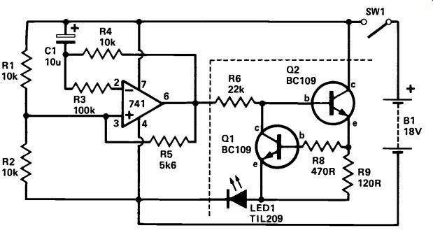
This circuit produces a low frequency square wave, using a 741 operational amplifier as a comparator. Indication of the frequency is provided by a light emitting diode (LED), illuminating when the output voltage is high.
By changing the values of C1 (10u) and R4 (10k) the frequency can be altered. Reduction of C1 or R4 increases the frequency; an increase in value reduces the frequency. If the frequency is above approximately 30Hz the LED will appear to be on continuously and the section after the dotted line can be omitted. Then the opamp output (pin 6) can be fed directly into an audio circuit (via a 10k resistor), and act as a straightforward signal injector.
Using the component values shown, the circuit will flash the LED at a rate of approximately 5Hz and if a socket is used, the circuit makes a useful op-amp tester.
To explain how the circuit operates, assume that the output of the 741 is low. The inverting input will be at a point below half supply. Also assume that C1 is not charged. The lower end of C1 will start to fall in voltage (due to the current through R4) until it reaches the voltage at pin 3. At this point the output of the 741 (which is comparing voltages at pins 2 and 3) will go positive. The voltage at pin 3 will rise to the other side of half supply and C1 will repeat, causing the 741 output to follow a squarewave.
+++++++++++++++++++
Low Frequency Oscillator
 .
.
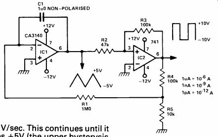
IC1 is a MOSFET op-amp. Thus its input bias current is very low in deed, typically 10pA as compared with 100nA for a 741. This allows very low current designs to be produced. The circuit shows an integrator (IC1) and a Schmitt trigger (IC2). Imagine that the output of the Schmitt is high (+10V). The voltage at the junction of R4, R5 is approximately +1V. This pushes a current of 1uA through R1 which then charges C1. Thus C1 (the output of IC1) ramps down at a rate of 1/C which is in this case 1V/sec.
When this voltage reaches -5V, the Schmitt trigger flips over into its low state (-10y). Now the current through R1 flows the other way, and the output of IC1 ramps up at 1V/sec. This continues until it reaches +5V (the upper hysteresis level of the Schmitt). The Schmitt trigger then jumps to its high output and so the period process re peats itself. The circuit produces a square wave (±10V) and a triangle (±5V) output. Using the components shown the period is 20. To get 200 seconds make R1=10MR; to get 2000 seconds make R1+10yR,R5=1R.
++++++++++++++++
Phase Shift Oscillator
 .
.
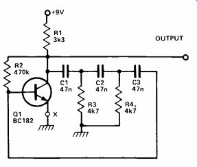
A single transistor can be used to make a simple phase shift oscillator. The output is a sinewave with a 'lump' in it, which means that the distortion content is rather high, about 10%. This is not al ways a problem; quite often when generating audio tones a high harmonic content will make a more interesting sound. The sine wave purity can be increased by putting a variable resistor (25 ohms) in the emitter lead of Q1. The resistor is adjusted so that the circuit is only just oscillating, then the sinewave is relatively pure. However, if the power supply level varies, the oscillation may cease altogether.
The operating frequency may be varied by putting a 10kR variable resistor in series with R3, or by changing C1, 2, 3. Making C1, 2, 3 equal to 100nF will halve the operating frequency.
++++++++++++++++++
Op-Amp Oscillator (2)
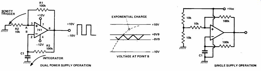
An op-amp can be made to oscillate, generating a square-wave output. The circuit is a Schmitt trigger and an integrator rolled into one.
To understand the operation, imagine the output is high; C1 is charged up via R3. The voltage at point 'A' is +0.9 V due to the resistor divider network R1, R2. When the voltage at B exceeds this, the output of the op amp flips into its negative (low) state. C1 is therefore discharged by R3. When the voltage on C1 reaches -0.9 V, the reverse process occurs and the op amp output flips back to its high state. Thus the circuit oscillates producing a square wave going from +10v to -10v.
The frequency of operation can be obtained from the voltage changes on C1. This is the truncated section of an exponential charge/discharge curve, but we shall ignore this and assume that the curve is linear (which it almost is).
The frequency can be obtained from the formula
F=--I / Δ VxC Hz
where I is the charging current (approximately 100µA), AV is the charge across C1 (3.6 V) and C is the capacitance in Farads.
+++++++++++++++++++
HF TTL Clock
 .
.
 .
.
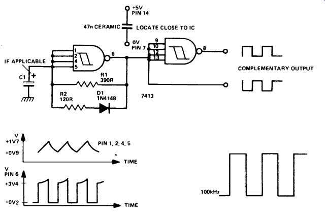
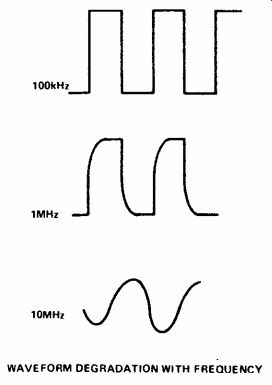
A squarewave oscillator with complementary outputs and a frequency range of 20Hz to 10MHz can be made from one IC, a 7413 which is a TTL dual, Schmitt trigger. The oscillator is self starting and runs from a 5V supply, current drain 20 to 30mA. The 7413 is a Schmitt trigger with hysteresis levels (at its input) of +0.9V and +1.7V. That is when the input level exceeds +1.7V the output jumps to a low condition (+0.2V). When the input voltage is lowered it needs to fall below +0.9V before the output jumps back to a high condition (+3.4V).
When the Schmitt trigger is connected as shown the device will oscillate. Imagine the output is high. C1 is charged up via R1.
When the voltage on C1 reaches +1.7V, the output falls to +0.2V.
C1 is now discharged via R1 in parallel with R2 (D1 is now for ward biased) until the voltage on C1 reaches +0.9V. Then the output jumps to a high state and the process repeats itself. The second Schmitt trigger merely inverts the squarewave output. The frequency of operation is given by the formula:
F=2x10^-3 / C1
where F is in Hz and C1 is in Farads.
++++++++++++++++++++
8038 Signal Generator
 .
.
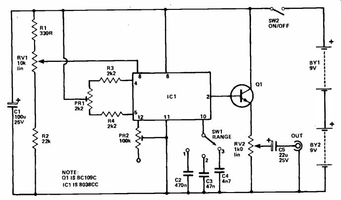
Although the 8038CC is not cap able of generating an extremely pure sinewave, it is capable of producing an output of high enough quality for general audio testing. The simple circuit shown here covers the audio frequency spectrum in three ranges - less than 20Hz to more than 200Hz; less than 200Hz to more than 2kHz, less than 2kHz to more than 20kHz.
The output amplitude is continuously variable up to a maximum of about 550mV rms and is from a low impedance source.
The 8038CC oscillates by first charging a capacitor via a constant current source and then discharging it through another constant current generator, It thus generates a triangular waveform. This is then fed to a trigger circuit to generate a squarewave signal and to a non-linear amplifier which "rounds off" the signal to give a sinewave output of reasonable purity. C2 to C4 give the three ranges. R1, RV1 and R2 form a potential divider circuit, which is used to control the charge and discharge currents of the timing capacitor. RV1 thus acts as the fine frequency control. PR1, R3, R4 balance the charge and discharge currents, so that a symmetrical output is obtained. PR2 is part of the sinewave shaping circuitry and is adjusted for maximum purity.
The sinewave output at pin 2 of IC1 is at a high impedance and is, therefore, coupled to the output via an emitter follower buffer stage using Q1. RV2 is the output level control, and C2 provides DC blocking at the output.
With the unit adjusted for a fairly low frequency output (about 50-200Hz), it should be possible to hear the main fundamental frequency plus the higher frequency harmonic signals. The output can be monitored using a crystal ear phone or amplifier/loudspeaker.
PR1, 2 are adjusted to minimize the harmonics.
(adapted from: Electronics Digest (Vol. 2 No. 3--WINTER 1981))
NEXT: Miscellaneous