Precision Half-Wave Rectifier
 .
.
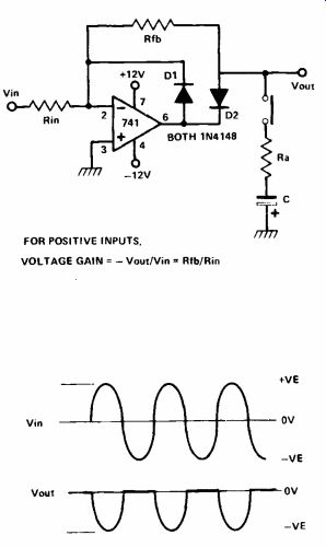
By putting a diode in the feedback loop of an op amp, a precision rectifier can be constructed. Normally a diode will need to be for ward biased by 0V6 before it will start conducting, so if you want to half wave rectify a low sine-wave (say 0V1 peak -to -peak) it is almost impossible to do it with just a diode.
However, by using an op amp it is possible to get this diode to drop to below 1mV in most applications. Referring to the circuit, imagine Vin goes positive; then the output of the op amp will swing negative to such an extent that D2 will be properly biased and will draw current through the feedback resistor Rfb. In fact the op amp adjusts its output so that the voltage at pin 2 is virtually at 0V (virtual earth). Thus the output voltage:
Vout=Vin x Rfb/Rin
... which is just like a normal op amp.
The diode D2 doesn't seem to have affected things and this is true for positive inputs even as low as a few millivolts. When Vin goes negative, the output of the op amp swings positive, D1 conducts and maintains a virtual earth condition and D2 is reverse biased. So, now the output is just Rfb connected to effectively 0V.
What this means is that there is only an output voltage (negative) for positive going inputs; when the input goes negative, the output is zero. That is, the input signal has been precisely half wave rectified.
Now, if the Ra, C network is connected to Vout, the half-wave rectifier can be turned into a negative envelope follower. When Vout goes negative, C is charged via Ra, Vout is unaffected whilst C is being charged. When Vout returns to wards 0V, C discharges through Ra and Rfb. If C and Ra are correctly selected then a contour of the envelope of the signal will be produced at Vout. For an envelope attack time of 1 millisecond (1kMz), with an envelope release time of 100 milliseconds, make Rin and Rfb 100k, Ra 1k and C 1uf.
+++++++++++++++++++
Electric Thermometer
 .
.
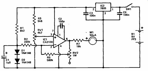
This thermometer covers the range 0 to 50 degrees Centigrade with a linear scale so that the temperature can be read directly from a 50uA meter. A range of 0-100 degrees Centigrade can be obtained by substituting a 100uA meter.
The unit uses silicon diodes D1 and D2 as the temperature sensors and these would normally be mounted in some form of probe which can be positioned many meters away from the other circuitry, if necessary. C1 filters out any noise picked up in the connecting cable. D1 and D2 are given a small forward bias by R1, so small that there is no significant self heating of the diodes. The voltage produced across the diodes is nominally 1V2 but it actually varies by about 2mV per degree C per diode, or about 4mV across both diodes. This voltage is fed to the input of an op amp inverting amplifier, IC1. With the probe at 0 degrees C (which can be achieved by immersing the probe in ice) RV1 is adjusted for the highest voltage at IC1's non-inverting input that gives zero output voltage. This compensates for the quiescent voltage across the diodes, and gives zero reading on the 1V FSD voltmeter circuit connected across the output of the amplifier.
If the diodes are heated to 50 degrees C the voltage across them will fall by approximately 200mV, this is amplified by a factor of 5 by the amplifier to give about 1V at its output, roughly full scale deflection of the meter. In practice RV2 is used to adjust the gain of the amplifier so that precisely full scale deflection is produced.
Of course RV2 can be given the correct setting with the probe at any known temperature which corresponds to a reasonably substantial meter deflection.
The circuit requires a very stable supply of about 5V, obtained from a 9V battery using a 5V monolithic regulator (IC2). C3 and C4 should be mounted close to IC2 in order to prevent instability.
++++++++++++++++
Insect Repellant
 .
.
It seems that mosquitoes and other nasty insects only mate at certain times and except for these times the two sexes are most unfriendly, in fact they stay well away from each other. It has also been reliably established that it is only the female of the species that actually bites. The third fact that we need to know is that the male mosquito (and this applies to other bugs as well) beats its wings at a slightly different rate than the female - this is one way that they identify each other. From these gems of information it will be seen that if one electronically simulates the sound of a male mosquito, the females will steer well clear.
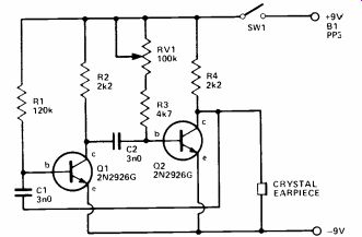
The circuit shown is a simple audio oscillator whose frequency of operation can be varied over a wide range, in fact from about 500Hz to 10kHz and this will take in the range of all the common bugs.
The circuit is a straightforward multivibrator with RV1 altering the audio frequency. This produces a square wave which is applied across the small crystal earpiece connected between the collector of Q2 and the negative line.
Crystal earpieces have a very high impedance and it will not affect the operation of the circuit. Almost any transistors can be used in this simple circuit but if PNP types are used the battery supply should be reversed. The values of the capacitors are not too critical either and if others are used and it is found that the frequency range is not adequate, R1 can be altered to bring it back to the right sort of range. The current consumption is low, 2-2mA and, varies slightly with the frequency, but a PP3 battery will last for a while; after all, the unit will have to be left on for long periods. None of the components need be large and the unit can be built in a small box to fit into a jacket pocket with the components arranged so that the ear piece is external.
Adjusting for the right frequency is a matter of trial and error.
(adapted from: Electronics Digest (Vol. 2 No. 3--WINTER 1981))
NEXT: Experimenter's Design Notes