Christmas Tree Lights Flasher
The usual method of getting the lights on a Christmas tree to flash on and off is to use a bimetal -strip type flashing bulb in the series chain of bulbs. As this switches on and off it breaks the circuit to all the bulbs so that they switch in unison. One drawback of this system is that most flashing bulbs provide a rather irregular flash rate; another is that it cannot be used to operate two sets of lamps.
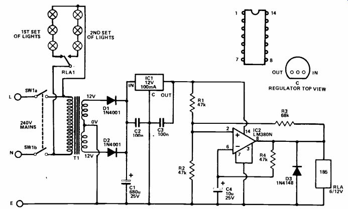
Both these problems can be overcome by using the simple circuit shown here. It is a low frequency oscillator (about 0.5 Hz) which controls the lights via a re lay. Thus the lights are switched on for periods of about one second in duration at intervals of roughly one second. By using a changeover relay contact it is possible to use two sets of lights with the relay switching the power alternately from one set of lights to the other. If this alternate mode of operation is not required, then one set of lights is simply omitted.
The unit is powered from a simple stabilized mains power supply having on/off switch SW1, stepdown and isolation transformer T1, push-pull rectifier D1 and D2, smoothing capacitor C1, and 12V monolithic regulator chip IC1.
C2 and C3 aid the stability and transient response of IC1, and should be mounted physically close to this component.
A well known oscillator configuration is used here, but it is a little unusual in that it employs an audio power amplifier IC, rather than the more normal operational amplifier device. However, the LM380N audio IC can be used in operational amplifier type circuits.
In this application it has the advantage of having a power output stage that can directly drive the relay with the high current it re quires. D3 is used to suppress the high back EMF which is generated across the relay coil as it de-energizes, and which could otherwise destroy IC2.
The switch on and switch off times of the circuit are proportional to the value of C4, and if desired they can be altered by changing the value of this component.
+++++++++++++++++++++
Egg Timer
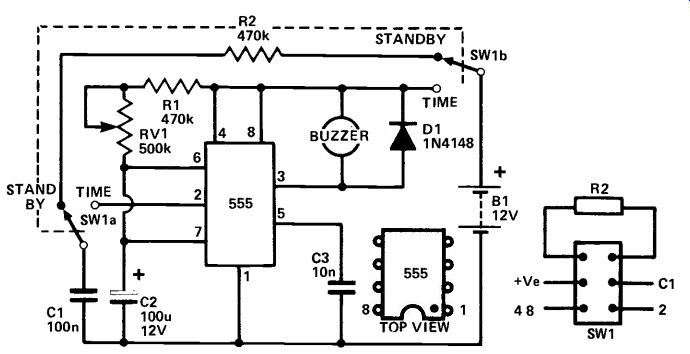
The 555 (IC) is one of the most useful timer devices available. In this circuit it is wired up as a 'triggered monostable.' Capacitor C1 is normally charged via R2 when the unit is in standby mode; when power is applied (switch SW1 to time), the trigger pin receives a pulse from C1, and the output goes high for a period determined by C2, RV1 and R1. When the time period is over the output pin returns to a low voltage and the buzzer turns on, indicating - your egg is ready! D1 is to prevent reverse induced voltage caused by the buzzer damaging the 555. When switched back to standby the buzzer supply is removed and C1 is recharged.
The time period can be varied between 2 and 3 minutes with the component values shown. For shorter periods reduce C2 or R1; longer periods are given by in creasing C2. Values of R1 and RV1 in total should not be more than 1MR, and C2 should not be more than about 500u - larger values will probably result in erratic time periods. C2 should have low leakage current characteristics if long time periods are required. If erratic time periods are produced a pushbutton (normally open-circuit) reset switch can be connected across C2. This will ensure complete discharge of C2 between cycles, if operated prior to each timing period.
The buzzer can be any 12V type, as long as it consumes less than 200mA, as this is the maximum the 555 can provide. Alternatively, a relay can be used to operate a remote buzzer or light.
++++++++++++++
Table Lamp
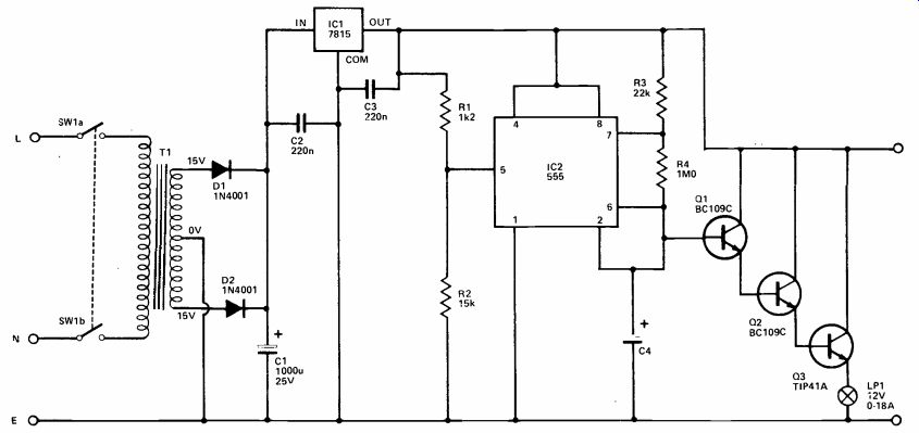
This circuit is for a decorative table lamp that produces a slowly changing background color. The unit can have a number of lightbulbs of different colour, each modulated at a different rate, giving constantly changing blends of colour.
The circuit is powered from the mains via a stabilized power supply. T1 provides safety isolation and a voltage step down; its centre tapped secondary feeds a straightforward push-pull smoothing and rectifier network. The resultant DC supply is fed to regulator device IC1, which gives a stabilized 15 volt output. C2 and C3 are de-coupling components and should be mounted physically close to IC1.
The remaining circuitry is used to control one lamp. This must be duplicated for each additional lamp, and for best results at least three lamps should be used. There is no need to duplicate the power supply which can power up to five lamp circuits.
IC2 is a 555 device used in the astable mode. In this case R1 and R2 have been used to raise the two threshold voltages from their normal levels in order to make the unit more efficient. The roughly sawtooth waveform produced across C4 is used to control the lamp by way of a triple Darlington buffer stage.
The value for C4 gives a cycle time of about 4 seconds per uF. A three lamp version could therefore have values of (say) 10uF 33uF, and 100uF. These must be good quality components, preferably tantalum bead types.
++++++++++
Door buzzer (1)
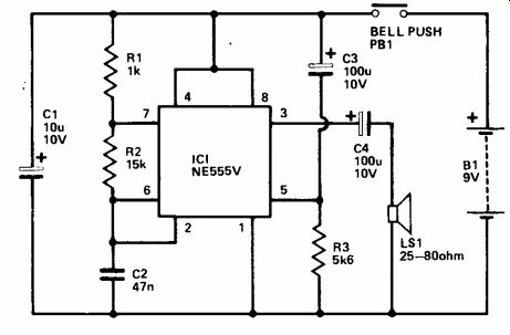
This design provides a novel door buzzer signal which starts as a low pitch and gradually rises in frequency.
The normal method of oscillation for the 555 is for the timing capacitor (C2) to charge up two thirds of V+ via two timing resistors (R1 and R2). The IC is then triggered and C2 is discharged through R2 and an internal transistor. The IC resets when the charge voltage drops to one third of V+, with the discharge transistor switching off and C2 commencing to charge up to the trigger potential once again.
This particular circuit does not oscillate in precisely this way, since the network comprised of R3 and C3 is used to shunt the potential divider (within the IC) which sets the trigger voltage. When SW1 is initially closed, C3 will be discharged and the trigger voltage will be raised. This increases the charge and discharge times of C2, and reduces the frequency of operation. C3 is quickly charged through R3 though, and after about one or two seconds the trigger voltage will have fallen to a level set by R3 and the internal potential divider. R3 pulls the trigger voltage below its normal level, reducing the charge and discharge times of C2 and causing an increase in the operating frequency.
Thus, as C3 charges up, the output frequency is swept upwards, producing a novel and effective signal.
The main output at pin 3 of the 555 goes high during the charge period, and low during the discharge period, producing a rectangular waveform of low enough impedance to drive a speaker with up to a few hundred milliwatts of signal.
+++++++++++++++
Home Intercom
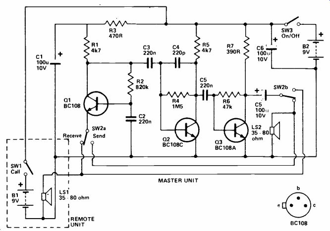
This intercom uses a straightforward three transistor amplifier which gives quite a good quality output (by intercom standards) and an adequate output power of a few tens of milliwatts.
As is normal practice with intercom designs, the loudspeaker in each station also doubles as a moving coil microphone. The position of SW2 determines whether the slave unit is 'sending' and the master station is receiving, or vice versa. Ideally this should be a biased switch which automatically returns to the 'receive' position when released. If it is not a biased switch, it could be left in the 'send' mode, preventing the remote station from calling the main one. SW3 is the ordinary on/off switch at the master station.
The amplifier is a three stage unit with capacitive coupling between stages. A common base in put stage (Q1) is used as this gives a low input impedance. This is desirable as it minimizes stray pick up of mains hum and radio interference in the connecting cable, and it also gives a good match to the microphones. The following two stages are both straightforward common emitter amplifiers.
C4 rolls off the high frequency response of the circuit and this aids stability. It can also help to prevent RF breakthrough.
The prototype was tried with connecting cables up to about 10 meters or so long, and gave perfectly good results. It should work with considerably longer connecting cables if necessary. A three core connecting cable is required and this can conveniently be thin, three cored mains lead.
++++++++++++++++
Doorbuzzer (2)
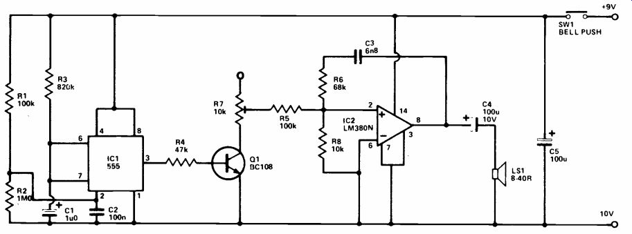
This is a two-tone doorbuzzer of the type that produces an initial tone for about one second, followed by a tone of lower pitch.
The audio tone is generated by IC2 which is an LM380N audio power amplifier. The frequency of oscillation is governed by the values of R6, R8, and C3. The specified values give an operating frequency of about 500Hz. The output from IC2 is fed to a loud speaker via DC blocking capacitor C4, and an output power of nearly 1 watt rms is obtained using an 8 ohm speaker.
The two-tone effect is obtained by the inclusion of IC1 and its associated components. This is a 555 IC connected in the monostable mode; it produces a positive output pulse of just under one second in duration (set by R3 and C1) when a negative trigger pulse is applied to its pin 2. Such a pulse is produced at switch on, since C2 will initially be uncharged and will take pin 2 of IC1 to the negative supply potential. C2 rapidly charges by way of R1 though, so that the trigger input is quickly taken positive, and does not re main negative at the end of the output pulse (this would have the effect of lengthening the output pulse). When power is removed from the circuit, R2 rapidly discharges C2.
Q1 is biased hard into conduction by the output pulse from IC1, and it therefore effectively connects the series resistance of R5 and R7 in parallel with R8. This increases the operating frequency of the oscillator by an amount that is controlled by R7. At the end of the pulse from IC1, the oscillator operates at its normal, lower frequency, giving the required two tone effect.
(adapted from: Electronics Digest (Vol. 2 No. 3--WINTER 1981))
NEXT: Power Supplies