Make useful and inexpensive ammeters, power meters, or temperature indicators from Duracell's Copper Top Testers.
by BRIAN MCKEAN
DURACELL INC.REVOLUTIONIZED the marketing of consumer electronics batteries with its Copper Top Tester, a disposable instrument for measuring power cell charge that is built into the blister packages for its products. The tester consists of a thin-film resistor combined with a liquid-crystal bargraph display. This article shows how the tester can be recycled to make low-cost ammeters, watt meters or transition temperature sensors.
The tester provides a reliable indication of the charge on a power cell or battery in seconds. All you do is position positive and negative terminals of the cell to match the corresponding contact pads of the tester, insert the cell between the contact pads, and squeeze the pads with thumb and forefinger down on the cell terminals.
After a few seconds you'll see a colored band gradually rise on the face of the tester. When it stops rising, observe the height of the column: If the colored bard does not rise above the red "replace" zone. (or is only slightly above it), dispose of the cell However, if the stripe stops near the top of the column, you can be assured that you have a fresh, reliable cell.
The tester is an attractive feature on the product package, especially for those people who buy lots of disposable cells and do not own a separate battery tester-which means most of the population. Before discussing the practical instruments that you can make from a re cycled Copper Top Tester, lets find out how it works.
How it works
The tester is an assembly on a thin plastic substrate of a tapered thin-film resistor back-to back with a colored stripe coated with a photo-chromic liquid-crystal emulsion. Both sides of the tester are shown in Fig. 1.
The apparent rising color band or column is really the result of a progressive state change of the heat-sensitive liquid-crystal film. The optical density of the liquid-crystal film changes at a transition temperature of 43°C (109.4°F). The liquid crystal is opaque below this threshold and transparent above it. As the heat migrates across the plastic substrate, a gradual transition from opaque to transparent occurs, slowly revealing the underlying colored stripe.
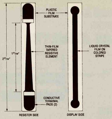
FIG. 1--DURACELL'S COPPER TOP TESTER: Resistive element side (left) and
liquid-crystal thermo-chromic display side (right).
When a cell is clamped between the tester's conductive pads, current flows in the tapered thin-film resistor, raising its temperature in accordance with the power law.
Different versions The patented tester (Duracell Inc. No. 4723656) is produced in different versions to test most standard alkaline cells--AA, C, and D, for example.
The deposition of resistive film is approximately 0.001-inch thick. As shown in Fig. 1, it is about 1-11/16-inch long, tapered from 3/16-inch at one end to 1/16-inch at the other end.
The resistance values of the element are about 6 ohms for the AA and C cell tester and 4 ohms for D cells. The resistive wedge is terminated at both ends by conductive-film pads that act as terminals. Although more conductive than the resistive elements, the pads add nearly 1 ohm to the value of the resistive element if the measurement is made from the extreme ends of the pads.
For example, the resistance of a D-cell tester element taken across both ends is about 3.7 ohms. But if the measurement is taken from the ends of the pads, the overall resistance is about 4.6 ohms.
The heating produced by the element is proportional to its resistance and the square of the applied voltage. The tapered element linearizes the liquid-crystal display. As in any thin-film resistor, the resistance at the wide part of the taper is less than it is in the narrow part. As a result, the narrow region dissipates more power than the wide region. This means that a weak cell, which delivers less current, can't heat up the wide region enough for the liquid-crystal film to reach its transition temperature.
The display element is a coating of thermo-chromic liquid-crystal emulsion 0.001-inch thick by 3/32-inch wide.
The tester is bonded to the in side of the clear plastic blister package with a welt over the liquid crystal bargraph to protect it during manufacture and use.
This cover reduces the sensitivity of the element to environmental temperature changes and prevents it from contacting hot objects directly.
Recycling the tester
The tester can be removed from the bubble pack by care fully peeling it off. Removal will probably damage the printed legends on the package, but they are not important in the recycled applications. You will want to calibrate any devices you make from the testers and then mark the display face of the tester with graduations that are appropriate for its application. You might also want to add appropriate numbers to match those graduations.
To obtain the most accuracy from any instruments you make from these testers, the instrument should be calibrated only after the tester is installed in its final package so that it will be stabilized in its normal thermal environment.
A suggested method for re mounting the tester on a rigid substrate for experiments or making instruments is shown in Fig. 4. The conductive con tact pads on each tester are coated plastic, so they cannot be soldered. However, adequate electrical contact can be made with brass or bronze leaf or coil springs. Copper or brass screws, washers and nuts can also be used to make satisfactory electrical connections.
Figure 4 shows how small coil springs can be used as contacts. Pierce the centers of the pads with a pin and twist the springs into the holes. The springs act as connectors for the tester, and permit it to be mounted to a rigid substrate.
The free ends of the spring can be straightened to form leads which can be soldered to a suit able rigid conductor, such as blank circuit-board material.
If you use this method, straighten the spring ends to shapes that permit them to be soldered to a conductive surface before twisting the springs into the tester's terminal pads. When soldering the ends of the spring to the conductive surface, hold them with metal tweezers or a folded copper strip to conduct away heat that would flow up the spring and melt the plastic pads.
In this mounting method, the copper cladding was removed from the region on the strip between the two terminals to provide electrical isolation. A thin strip of foamed plastic about 1 /16-inch thick provides suitable thermal insulation.
Alternatively, you could use small copper or brass screws and nuts with a stack of small brass washers under the terminals at each end to provide the necessary 1/16-inch tester stand off distance.
Building an ammeter
The tester can be recycled as the sensor and display for a compact AC or DC ammeter with a useful operating range of 100 to 400 milliamperes.
Figures 2 and 3 are normalized voltage vs. current curves obtained from salvaged testers. They will permit you to calibrate any ammeters you build. Figure 2 was plotted from 5-ohm resistive elements taken from AA and C cell testers, and Fig. 3 was plotted from 6.7-ohm elements taken from D-cell testers. These graphs also correlate the apparent height of the color bar with applied voltage.
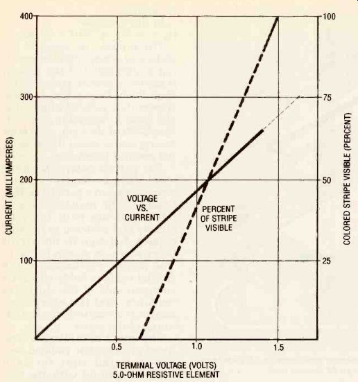
FIG. 2--CURRENT VS. VOLTAGE and voltage vs. visible stripe graph for an
AA cell tester (5-ohm resistive element).
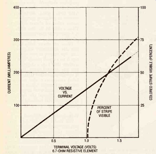
FIG. 3--CURRENT VS. VOLTAGE and voltage vs. visible stripe graph for a
D cell tester (6.7-ohm resistive element).
An unmodified tester will not respond to current less than 100 milliamperes. However, the upper range of the ammeter can be extended by connecting a suitable shunt resistor across the tester.
An ammeter made from a tester will not be a precision instrument, but with careful calibration, a reading resolution of ±25% full scale can be obtained. Calibration points can be made with pen and ink and clear numbers can be transferred with decals or with artist's transfer sheets.
Flexible insulated leads terminated with miniature alligator clips can be soldered or clipped to the conducting pads on the tester substrate (Fig. 4). Small plastic boxes with hinged covers can becomes cases for the miniature ammeters.
RF dummy load
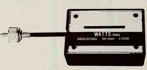
The tester-substrate assembly shown in Fig. 2 can be adapted to form an indicating radio-frequency dummy load as shown in Fig. 5. The tester actually measures the power dissipated by a resistive element, so it can measure alternating current power as well as direct current power. Because the resistive element is a film, it has low equivalent inductance and capacitance; this characteristic makes it acceptable for measuring radio frequencies.
Figure 5 shows a concept for building a low-power (less than 8-watt) 50-ohm load. The circuit can be calibrated with either a DC or low-frequency AC source. The connector installed should match the socket on the intended radio-frequency source or sources.
The resistive load is placed in series with the tester's resistive element so that their sum equals approximately 50 ohms.
A practical approach is to parallel ten standard 1-watt, 470-ohm, carbon composition resistors. They are capable of withstanding up to 8 watts of input power, and they provide an approximate resistance of 47 ohms in accordance with the rule for calculating the resistance value of multiple resistors in parallel.
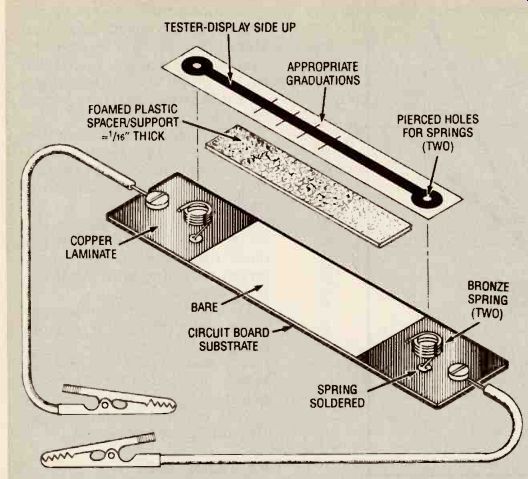
FIG. 4--ONE WAY TO MOUNT THE TESTER for practical applications such making
an ammeter (shown) or as the indicating element in an RF dummy load.
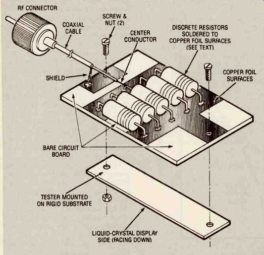
FIG. 5--AN INDICATING 50-OHM RF DUMMY-LOAD wattmeter made from the tester.
One-watt resistors are connected in parallel to provide approximately 50-ohms
resistance and be able to dissipate up to 8 watts.
In this example:
R_T = 1/10 R = 470/10 = 47 ohms.
The cluster of parallel resistors in series with the nominal 5-ohm value of the tester's resistive element yields a 52-ohm load. Experiments have shown that this 52-ohm value will have a negligible effect on the VSWR of the load, even after taking into account the individual resistor tolerances.
The carbon composition (or thick-film carbon) resistors were ganged in a parallel configuration. The resistor leads at both ends are bent into "L" shapes and soldered to isolated copper-clad regions on circuit board stock, as shown in Fig. 5.
The center conductor of the coaxial cable is soldered to the common side of the cluster of resistors, and the other common side is connected to the terminal of the tester.
The cable shielding is soldered to a separate isolated copper-clad pad that forms a common ground with the second terminal of the tester.
If you want to use the tester with the nominal 6.7-ohm resistance element, you can mix five 1-watt, 470-ohm resistors with five 1-watt, 430-ohm resistors to obtain a parallel resistance value of about 45 ohms.
This value in series with the 6.7-ohms will also provide a satisfactory load.
There are many ways to pack age the wattmeter for practical use. For example you can pack age it in a small plastic box with a cover that has a cutout to admit the coaxial cable. However, it is recommended that the parallel resistors and exposed length of coaxial center conductor be shielded with metal foil or screen to prevent the escape of unwanted RF emissions from the load.
temperature indicator
The tester can be used with out electrical connections to indicate the transition tempera ture of 43°C (109.4°F). For this application, cut off the terminal pads and mount the part flush with the surface of the object whose temperature is to be determined. This instrument can be used to warn you that the temperature at the surface of equipment or within an en closure exceeds 109.4°F.
You can also mount the tester on a 1 by 4 inch piece of circuit board to make a simple transition thermometer that you can move from place to place to determine if objects or spaces are above or below that temperature.
Applications precautions
Remember that the tester is a sensitive thin-film sensor-display that can be damaged by excessive heat or current. Here are some precautions to take that will assure good results in your experiments and projects:
Do Not use the tester in direct sunlight or where the ambient temperature never falls below 42°C.
Do Not mount the tester directly to heat-conducting material when making an ammeter. Heat conductors will degrade the tester's response time and sensitivity. A 1 1/16-inch thick insulating "cushion" will provide adequate thermal isolation.
Do Not pass more than about 300 milliamperes through the resistive element. (See Figs. 2 and 3.) If higher operating currents are required, shunt the resistive element with a discrete resistor of the proper value.
Do Not experiment with or use the tester where flammable or explosive gas or other materials are present. If overheated, the tester will act as a pyrotechnic fuse.
Do Not make sharp bends or creases in the tester because the resistive element will be damaged.
------------------
Also see: Aurora Monitor