This section contains a random collection of hints and shortcuts which the author has acquired over the years.
Checking Power-Supply Current: The current drain on a power supply can be determined without breaking any wires by observing the ripple across the first filter capacitor on a calibrated oscilloscope and calculating:

where C is the value of the first filter in farads, V is the peak-to-peak ripple voltage, and t is the time between charging pulses in seconds. The accuracy of the determination is limited by the capacitor tolerance, which may be as poor as - 20 + 80% for electrolytics.
Is the Zener Conducting? A conducting avalanche diode (8 V and up) will show random noise of about 3 to 10 mV p-p across its terminals. Use a sensitive scope on ac coupling. Absence of noise usually means absence of avalanche current. True zener diodes (6 V and below) show little noise even when conducting.
Sharpening a PC Drill: A dull dill burns the circuit-board material and leaves ridges around the hole which interfere with soldering. Conventional sharpening of such small dills is impractical, but two cuts from an old pair of cutting pliers will leave a good cutting edge. Cant the cutters about 20° from a light angle and cut off about 1 mm of the end, then rotate the bit 180° and even up the other side.
Caution: The end pieces will fly! Wear safety glasses and point the end toward the floor.
Is It Line Noise? If a noise signal or false trigger is encountered when troubleshooting with the scope, switch the trigger source to line. If the display holds still, the noise is ac-line-related.
Meter Loading? If a VOM is loading the circuit under test, the voltage reading will change with changing scales (2.0 V on the 2.5-V scale and 3.0 V on the 10-V scale, for example). Of course, if a second meter is available, the loading of the first can be observed on the second as the first is connected and removed.
Tape should never be regarded as a permanent fixture, as it will eventually unwrap itself. A taped joint can be made to hold longer by applying a "flag" over the wraps as shown in Fig. 25-1. The mating adhesive surfaces hold better than the wrapping.
Printed-Circuit Tracing: When troubleshooting a printed-circuit board, shine a light on the bottom (foil) side of the board and view the board from the top (component) side where probe clips can be attached. The light will let you see the conductor tracks through the board.
Measuring Overrange Resistors: Many DVM multimeters have an upper limit of 20 MB. Higher values can be measured by paralleling them with a previously measured high-value resistor and measuring the total:
For example, we measure a nominal 15-MB resistor (R1 ) as 14.83 MB, and parallel it with a nominal 22 MB unknown (R2), reading a total of 9.16 MB.
R2 = 23.96 MB
Safety: Keep a j-m lead with two insulated-handle needle-point probes handy for discharging filter capacitors before starting service work.
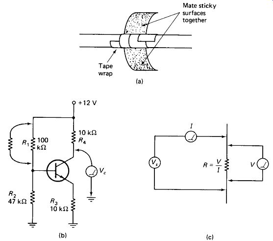
FIGURE 25-1 (a) Tape flag keeps wrapped tape in place longer, (b) Shunting
a resistor to observe the circuit response, (c) Separate contacts for measuring
low-value resistance: one set applies current, the other measures IR drop.
High Voltage: If you get involved in troubleshooting or prototyping the logic or low-level divers of a system, disable the high-voltage supplies by disconnecting a transformer wire or shorting the oscillator transistor of an inverter base-to-emitter.
This is not only for your personal safety-an accidental slip of the probe shorting the + 2000 V to the + 5-V supply can do untold amounts of damage.
Self-Oscillation at high frequencies (-100 MHz) will often not show up on the scope, but if moving your hand' near the wiring or touching the chassis causes changes in the instrument , s operation, self-oscillation is likely to be the problem.
You can often tell which stage is self-oscillating by bringing a screwdriver blade or grounded probe near each transistor case in turn. A different transistor may help, or the leads might be dressed closer to the chassis or farther apart from each other.
Changing Resistor Values can be an effective troubleshooting device. In Fig. 25-1 (b) for example, shunting a few hundred k Ohm across R1 should lower Vc.
Shunting R2 should raise Vc. Resistors in the 500-k Ohm to 10-k-Ohm range can be lowered by simply touching the fingers of one hand across them. Obviously, this trick is for low-voltage circuits only.
If a Failure Has Just Occurred, quickly touch all the transistors and ICs in the suspected area. The bad one will often have gotten very hot just before failure.
Watch out for burned fingers and high voltages on metal transistor cases.
Metal Transistor Cases, by the way, are usually electrically connected to the collector, and furnish an easy-to-get-at test point in troubleshooting.
Very Low Value Resistors may be measured with the test setup of Fig. 25-1 (c). The resistance of the probe wires will not affect the determination because the voltage across the current-carrying ammeter wires is not measured by the voltmeter, and the voltmeter wires carry almost no current.
Remote-sensing power supplies use the foregoing trick to regulate the voltage out at the load rather than at the supply terminals.
A Soldering Gun that won't heat up probably just needs the tip bolts tightened.
Cheap Panel Meters that are off zero and have no zero adjust can often be re-zeroed by holding a solder gun near and turning it on and off. The magnetic field from the coil in the gun body does it.
Plastic-Face Panel Meters sometimes get "sticky" and inaccurate because of static charge on the face. Simply moistening the plastic will free them up.
A Sensitive Microammeter Pointer will bounce around when the meter case is rotated if the terminals are open-circuited but will hold quite steady when they are shorted. You can tell if the coil is burned out in this way.
Loudspeaker Cones can be repaired with a piece of tissue paper soaked in nail polish.
Diodes Rated Above 1 kV usually consist of several series silicon diodes in a single case. Three silicon drops is more than the 1.5 V battery in the VOM, so the diode will measure open both ways. Use a 10-V supply and 10-kQ resistor in series with a 1-mA meter to test HV diodes.
A Short to Ground can sometimes be located with a scope or DVM that has 1-mV sensitivity, as shown in Fig. 25-2(a). A 1-mm-wide copper track has nearly 10 mS/cm resistance, so a short-circuit current of 100 mA will give an IR drop of 0.1 A X 0.01 B or 1 mV per cm along the shorted PC track.
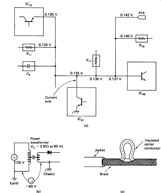
FIGURE 25-2 (a) Tracing milli-voltage to locate a short to ground, (b) Power
transformer couples about 60 V ac through a high capacitive reactance to the
chassis of an instrument with a two-wire line cord, (c) Pull the center conductor
out through a part in the shield braid when stripping coax cable.
Line Noise on the Chassis of an instrument with a two-wire line cord is coupled through stray capacitance of the power-transformer windings, as shown in Fig. 25-2(b). The instrument chassis will typically be at 0.5 V_line above earth ground, unless externally grounded. The stray capacitance varies, being larger for large power transformers, but generally lies between 200 pF and 0.003 uF. This represents a reactance range from 13 M-ohm to 880 k-Ohm and a current leakage of 5 to 68 uA.
Connecting the instrument chassis to a point other than ground means injecting 5 to 68 uA of 60-Hz noise at the point.
Hot Chassis? Ungrounded instrument chassis will measure 60 V "hot" to ground as explained above, but a 33-k-ohm resistor from the chassis to ground will cut the voltage to almost zero unless there really is a short to the ac line.
Stripping Coax: When stripping coax or shielded cable, loop the center wire out through a hole in the braid, as shown in Fig. 25-2(c).
Potentiometers tell a lot by the way they feel as they turn. A bumpy feel indicates a wire-wound type. A single bump indicates a broken wire or carbon track. Irregular bumps indicate a burned carbon track. If noise diminishes when you pull on the knob, wiper tension may be weak or the wiper arm may need cleaning.
Variable-Capacitor Plates are delicate and easily bent. If you listen carefully, you can hear the scraping of bent plates as the shaft is turned.
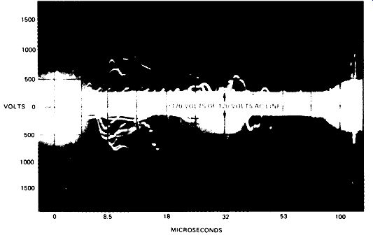
FIGURE 25-3 Oscilloscope recording of a household power line input (24 h).
Potentially damaging transients occur commonly on the ac power line.
Use a Toothpick to clear PC-board holes of solder when replacing components.
Heat the pad and leave the toothpick in until the solder cools.
Transients on the AC Line are documented by Fig. 25-3 to stress the need for generous safety factors on power-supply diodes and for varistor protection of line-operated equipment.
Don’t Leave a VOM on the Ohms Range: It could discharge the battery and, over an extended period, could cause the battery to leak corrosive material all over the circuitry inside. Instruments with orange-glowing neon or incandescent-filament digital displays should not be left on indefinitely if maximize display tube life is to be realized.
-----------------