Electronic equipment failures can cause economic and social problems ranging from irritated customers to airplane disasters and it is shallow to concentrate on troubleshooting without giving equal attention to trouble prevention. The chain of reliability includes as its links the component manufacturer, the circuit designer, the assembler, the operator, and the service technician. The process of assuring reliability begins at the earliest stages of product development.
24.1 DESIGNING FOR RELIABILITY
Component Specifications: In a high-reliability product, design specifications are drawn up on the desired temperature, vibration, humidity, and altitude limits of the finished product. A guarantee must then be obtained from the manufacturer of every component going into that product that his components will meet or exceed these specifications, or else a program of incoming-component testing must be initiated and continued for as long as the components are being received.
This is painstaking and expensive, but product reliability cannot be assured if component reliability has not been assured.
Design Documentation: Responsible design is not a matter of building a prototype with pots for each resistor and then measuring all the values once they have been adjusted for best operation. If the company is building an audio amp specified to deliver 25 W to an 8-ohm load down to 100 Hz, the designer should be able to produce a set of calculations showing that for the lowest guaranteed beta of the transistors at the lowest specified temperature and line voltage, and with all resistors and capacitors at their worst-case limits, these specs will still be met. The number of calculation sets that is required to take each of n components to its upper and lower limit is 2^n. To vary 10 components, this means 1024 calculation sets. In the days of hand calculation this would have been limiting, but ready availability of computer circuit-analysis programs removes all obstacles to its implementation.
Safety Factors: A common and highly recommended practice is to make the worst-case design limits a little wider than the specified operating limits: design for 102 to 130 line volts and publish 105 to 125 line volts, for example. Resistor power and non-electrolytic capacitor voltage are usually chosen for a safety factor of at least 2. Electrolytic-capacitor voltage, inductor current, and semiconductor power are typically given a 50% safety margin.
24.2 PROTOTYPE CONSTRUCTION
Breadboards, named for the wooden versions that were used several decades ago, are finally available at a reasonable price. They contain hundreds of spring-loaded sockets designed to receive a solid-wire end, component lead, or IC pin. Here are some hints for breadboard prototyping:
. Don't force large leads (like 1-W resistors or big electrolytics) into the sockets, or they will become too loose to hold the smaller leads. Solder on a lighter wire.
. Try to make the physical layout of the breadboard components look as much as possible like the schematic layout. This makes it much easier to follow the circuit and find things during troubleshooting.
. Use stick-on numbers on the ICs and transistors corresponding to numbers on the schematic.
. Do not twist wire ends together-the connection is bound to be intermittent. Use solder or an alligator clip.
. Do twist the insulated leads from power supplies and meters together-about one turn every 2 cm. This minimizes noise coupling and self-oscillation.
. Keep all leads short-about 30 cm maximum. Shielded leads may be longer. This combats self-oscillation.
. Self oscillation may still be a problem because of the longer leads and lack of shielding in the breadboard prototype. Using medium-power transistors in place of small-signal types often helps because of their lower fT. Ferrite beads on the input and supply leads, and a 100-pF capacitor from collector to base may also limit self-oscillation.
24.3 COMPONENT MOUNTING
Tool Selection: Obtaining a quality set of cutters and long-nose pliers for miniature work may require more travel and more money than you like, but it is worth the trouble. Neither should be more than 10 cm (4 in.) long, and the working end should be as narrow as possible. Insulated handles and spring-open jaws are advisable. A good cutter will snip a piece of paper as cleanly as a scissors and nip a hair off the back of your arm without pulling. A good pliers will close at the tip first, then back toward the jaws as more pressure is applied. Try picking up a sheet of paper with the very tip of the pliers.
Have a larger set of tools available for brute work. Don’t use your fine cutters for shearing bolts or your good long-nose for a wrench.
The kick when a sharp cutter shears a hard wire can send the wire end flying five meters or more. Point the wire end down, not up or at anyone's face when cutting. This kick has been known to cause component damage from the shock telegraphed up the lead. Placing a temporary bend in the lead between the component and point of cut will keep the shock from reaching the component.
Circuit-Board Mounting: Circuit-board components should be mounted horizontally unless they are designed for vertical mounting. The lead bends should allow plenty of room for a probe hook-do not crush the leads against the side of the component. If the component is operating near its maximum power dissipation, it should be kept a few millimeters above the surface of the board to allow air circulation.
The component leads should be cut leaving 2 or 3 mm on the foil side of the board. The lead end should be clinched back along the PC conductor track to hold the component. In prototype instruments where there is a strong likelihood that some components will have to be changed, it is advisable to cut the lead at 1 or 2 mm and solder it without clinching. When replacing a component, the new lead should be cut at an angle, leaving a sharp point for insertion into the hole, which may be partly clogged with solder. Figure 24-1 illustrates the foregoing concepts.
Components weighing more than about ten grams should not be mounted by the leads alone, but should have a clamp to hold them.
Terminal Mounting: Terminals should be used wherever a component lead is not long enough to reach its destination. A hanging splice along a wire run or a midair junction of wires or component leads is not acceptable.
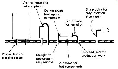
FIGURE 24-1 Proper and improper mounting of components on a printed circuit
board. (See the text.) Wires and leads should not be stretched to a terminal
point.
A "service loop" relieves strain and permits a reconnection if the wire should break at the terminal.
For production work, the lead end should be wrapped completely around the terminal and clinched, so that the joint is mechanically solid before soldering. A terminal with three or four wrapped connections is very difficult to unsolder, however, so for prototype work you may wish to use a single-bend hook at the terminal. Figure 24-2 illustrates these ideas.
24.4 WIRING
Wire Selection: Stranded wire must be used where there is any possibility that the wire will be flexed in use or during servicing, or in equipment subject to continuous vibration, such as in aircraft. Solid wire is easier to connect to most terminals, but may be used only where flexing will not occur.
Insulation should be selected for the anticipated environment. PVC plastic melts at a relatively low temperature, rubber deteriorates with age, cotton absorbs moisture, and enamel may crack or scrape off. Teflon is excellent but is a little more expensive and difficult to work with.
Wire Stripping: A nick in a wire becomes a stress point which leaves the wire vulnerable to a complete break from relatively mild flexing. Wire stripping with a knife or adjustable-pliers-type strippers is therefore absolutely forbidden.
Semiautomatic hand strippers with nonadjustable die-type cutters are acceptable, but care must be taken to use only the die hole for the proper-size wire.
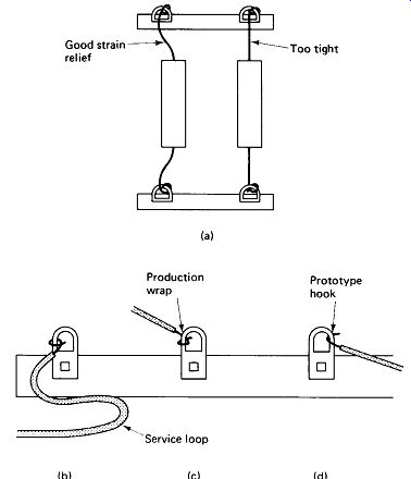
FIGURE 24-2 Proper wire-lead terminations: (a) leave slack in component leads
for strain relief; (b) leave enough extra wire so that it can be cut and re-terminated;
(c) wrap and crimp wire around terminal on production jobs; but (d) use a simple
hook where wire may have to be removed.
Using a too-small hole will certainly leave a nick. For production work all holes but the proper one should be ground out or single-hole dies should be ordered.
Thermal wire strippers use an unsharpened hot blade to melt rather than cut the insulation. The possibility of a nick is completely eliminated with this method, almost no force is required on the wire to pull off the insulation, and the stripper can operate in closer quarters than most cutting-type strippers. Heat and timing must be skillfully controlled to achieve a clean strip, however.
Preparation for Soldering: The length of the stripped wire end must be carefully controlled so that no more than 2 mm of bare wire is exposed between the solder joint and the insulation. On the other hand, the insulation must not protrude into the solder joint.
Care must be taken to avoid disturbing the lay of the strands after stranded wire has been stripped. It is common practice to tin the stripped ends of stranded wires by dipping them first in liquid rosin flux, then in a pot of molten solder. This keeps the strands from fraying and allows the wire end to be bent around a terminal without separated and protruding strands. If a ball of solder forms at the end of the wire after tinning it can be shaken off when hot or cut off when cold.
Stripped wires, etched circuit boards, terminals, and other items to be soldered should be kept in plastic bags if they are to be stored for any length of time before use. This prevents oxidation, which would hinder the soldering process.
24.5 SOLDERING EQUIPMENT
Solder Selection: Solder is an alloy of tin and lead which, when heated above its melting point, is capable of bonding with other metals, such as copper, near their surface. The alloy SN 63 (63% tin, 37% lead) is eutectic (yoo-TEK-tik), which means that it passes immediately from the solid to the liquid state (at 183° C for tin-lead). Other alloy proportions pass through a plastic state when cooling from the liquid state. This is undesirable because a cracked joint can result if the joint is moved while the solder is plastic. Non-eutectic alloys also melt at a higher temperature. The following table summarizes the commonly available alloys:
Tin/Lead Liquid Above: Solid Below:
63/37 183°C nrc 60/40 190°C 183°C 50/50 213°C 183°C 40/60 236°C m-c
The 60/40 alloy is generally acceptable, but 50/50 and 40/60 should not be used for miniature work. Only the highest-quality solder from a reliable manufacturer should be used. This is no place to look for bargains.
Liquid solder absorbs gases from the air and will oxidize if overheated or held too long in the liquid state. Oxidized solder has a dull granular appearance and forms jagged peaks when the pencil tip is removed. Once solder has oxidized, it must be removed from the joint and new solder applied.
Flux: Pure solder will not bond to most metals because of the thin oxide layer that forms on the surface of a metal exposed to air. Solder will bond to most metals if the oxide can be removed and the solder applied before a new oxide layer forms.
Mechanical or ultrasonic cleaning under the molten solder or in an inert-gas atmosphere can be used, but application of a chemical flux that removes the oxide when heated is the most practical and widely used method.
Fluxes are available that will permit the soldering of many aluminum and steel surfaces, but these should be used only under the most carefully controlled conditions, as they are likely to leave a residue that will cause corrosion after the work is completed. Solder for electronic use contains one or several hollow cores filled with rosin flux, and this is the only type that should be used for general soldering work.
In some cases, such as machine soldering, dip soldering, or dip tinning, it may be desirable to apply the flux separately from the solder. In such cases flux-less solder should be used. If solder with core flux is mixed with separately fluxed solder, the flux should be obtained from the same manufacturer, with a guarantee of compatibility to prevent the formation of corrosive residues.
Rosin flux itself is nonconductive, but it tends to collect dust and other foreign material which could accumulate moisture and lead to corrosion and current-leakage paths. Alcohol or a special rosin solvent should be brushed on the joint and wiped off to remove excess flux after soldering.
Soldering Pencils: A joint temperature of 275°C (527°F) for a period of 1 to 2 seconds has been found to produce the most reliable solder joints. For continuous production work a small ruggedly constructed soldering pencil rated at 25 to 30 W and operated from a small variable transformer to control temperature is recommended. Where soldering is done intermittently, as in servicing or prototyping, or where it is not possible to use a variable transformer to reduce tip temperature, a temperature-regulated pencil is recommended. They cost about five times the price of an unregulated pencil, but the ease of producing quality work with them makes the investment well worthwhile.
Unregulated pencils reach excessive temperatures while standing in their cradles, which restrict air movement and reflect heat back to the tip. This makes it likely that the solder will be oxidized and the rosin burned to a black crud which fouls rather than cleans the joint. A microswitch mounted on the soldering pencil cradle can be wired to cut the power to half while the pencil is in the cradle, thus providing some relief for this problem. Figure 24-3 shows the circuit.
A short narrow barrel allows the pencil tip to be guided more surely into dense circuitry without accidental damage to nearby wiring and components. A three-wire grounded-barrel design is recommended for work on circuits containing MOS devices. Soldering guns are not recommended for electronic wiring or component-lead soldering, although they are handy for an occasional job involving a bracket or heavy electrical wire.
Soldering-Pencil Tips: Thermostatically controlled pencils can use iron-plated tips which maintain a smooth surface for a very long time if well cared for. A standard soldering pencil will burn the plating off in a short time, however, so plain copper tips are recommended here.
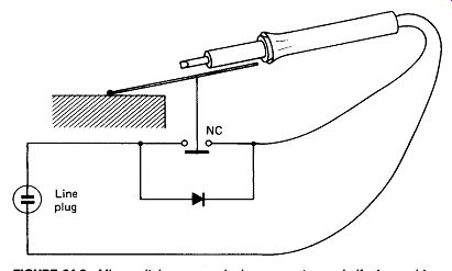
FIGURE 24-3 Microswitch opens reducing power to one-half when soldering pencil
Is In its cradle.
Copper actually dissolves slowly in molten solder, so it is very important to keep a sponge handy to wipe off the excess solder after each joint is completed.
When a copper tip becomes pitted or misshapen, it should be filed back to its original wedge shape. Plated tips should not be filed, of course, but they may be cleaned with a soft wire brush.
A new or freshly cleaned tip should immediately be tinned or coated with solder. Take a few inches of solder and wrap it around the cold tip, and then heat up the pencil. Once the solder melts, see that the entire tip is covered and then wipe off the excess solder.
Tips often screw into the barrel, and a loose tip or corrosion between the screw threads can keep heat from flowing to the tip. A tip frozen into the barrel by corrosion can destroy the whole pencil. Antiseize compound applied when the tip is first inserted is the cure for all of these ills.
24.6 HOW TO SOLDER
A good solder joint is made by heating the wire and terminal sufficiently so they will melt solder, applying the solder to the terminal (not the pencil tip), and removing the heat quickly.
Heat Application: The soldering pencil should be kept warmed up at the bench all day, not plugged in just before it is needed. Be sure that the tip surface is smooth, shiny, and clean of old solder and flux before starting. .Do not attempt to solder with a black, corroded tip.
Press the tip firmly to the terminal and against the wire to be soldered. A light touch will not transfer enough heat. Try to get as much contact between the work and the tip as possible. If the shape of the terminal limits the contact area, you may apply a tiny bit of solder between the tip and the work to serve as a heat-transfer bridge.
Solder Application: Quickly touch the end of the solder to the opposite side of the terminal so that the solder does not touch the tip of the pencil. As soon as the terminal becomes hot enough, the solder will melt and immediately flow all around the joint, forming a shiny fillet between the wire and the terminal.
Do not feed in more solder if the entire joint has been wetted.
You want to fillet in the space between the wire and terminal-not bury the wire under solder.
Cooling the Joint: Immediately upon seeing the solder flow into a fillet around the terminal, remove the pencil tip. Unless the terminal is unusually massive, it should begin to melt solder within one to three seconds of the application of heat.
Solder should flow completely around the terminal within one second of its melting, so the total heat-application time should not exceed 2 to 4 seconds. It is important not to leave the pencil tip on the work longer than necessary. The adhesive that bonds the copper foil to a circuit board is easily destroyed by overheating. Wire insulation may melt and solder may oxidize if excessive heat is applied.
It is essential that the joint be held motionless as it cools, or a cracked joint will result. This is the main reason for clinching wires mechanically tight before soldering. Blowing gently on the joint will greatly accelerate cooling.
A well-made solder joint will appear smooth, shiny, and concave between the wire and the terminal. Convex bulges or beads of solder indicate that the joint was not heated sufficiently or that too much solder was applied. Granular or jagged solder is evidence of excessive heating. Figure 24-4 illustrates soldering technique and joint problems.
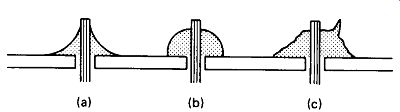
FIGURE 24-4 (a) A good solder joint is concave, smooth, and shiny, (b) Convex
bulges indicate too little heat or too much solder, (c) Dull, granular-looking
solder which forms peaks has been overheated.
A Rosin Joint sometimes results when the terminal surface refuses to bond with the solder, either because it was insufficiently heated or because the flux was unable to remove its oxide coating. The rosin (an insulator) may then act as a glue, holding the solder to the joint. The worst of it is that the wire will probably be in contact with the terminal, showing electrical connection on an ohmmeter. After a time in service, oxidation and/or vibration will almost certainly bring such a joint to an intermittent contact condition. A suspected rosin joint can be tested by attempting to wedge a knife or thin screwdriver blade between the solder and the terminal.
Rosin joints will usually crack under pressure, whereas the solder will shear before the solder-to-copper bond gives way in a good joint. When probing for rosin joints, be certain not to flex or strain the wires at the joint.
24.7 SOLDERING PROBLEMS
Difficulty in obtaining good solder joints may be caused by insufficient heating of the terminal, overheating of the solder or wire insulation, or inability to remove the metal-oxide coatings. Here are some solutions to these problems.
Cleaning: Wire ends, component leads, and terminal surfaces that are contaminated with a foreign substance (oil is a common one) or heavily corroded from long storage must be cleaned before soldering is attempted. A wire brush, a fine file, emery paper, or a copper kitchen scrub pad can be used. A folded piece of braid from coax cable shield wire makes a fine cleaning pad. Ultrasonic cleaning and chemical solvents may be investigated for special contaminants.
Tinning: Joints that take solder with difficulty may be worked more easily if the wire and the terminal are tinned (coated with solder) separately before the joint is made. Soldering is then simply a matter of melting the two solder coatings, rather than removing the oxide layers.
Abrasion: Mechanical scratching under the molten solder will sometimes break the oxide layer on a difficult soldering job. The pencil tip or a small knife or screwdriver blade may be used for this. It is likely that the solder will be overheated during this process, in which case it should be removed and new solder applied.
Anti-wicking: When stranded wire is tinned or soldered, capillary action may draw liquid solder up between the strands a millimeter or two under the insulation. The wire becomes rigid where solder bonds the strands together, so flexing occurs under the insulation at the end of the solder penetration. The wire may actually break at this point, and inspection will be unable to reveal the flaw.
To prevent this problem, an anti-wicking tool (Fig. 24-5) is used. This is a tweezer-like tool with a split-cup end for grasping the wire just below the insulation with the end protruding. Heat flowing up the wire is shunted to the tool and the wire under the insulation remains too cool to melt solder.
Heat Sinking: A variety of locking and spring-loaded clips are available to clamp onto a wire or component lead just above the joint during soldering. They may be used when there is danger of heat traveling up the lead and damaging a component or melting wire insulation.
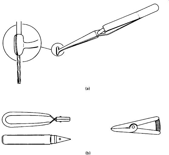
FIGURE 24-5 (a) Anti-wicking tool to prevent stiffening of stranded wire under
the insulation, (b) Heat-sink clips to prevent wire insulation and component
damage during soldering.
24.8 UNSOLDERING AND REWORKING
A joint will have to be unsoldered if the solder has oxidized from overheating, or if a modification is being made, or if a faulty component is being replaced.
Applying Heat: Press the pencil tip firmly to the solder to melt it as quickly as possible. Heat-sink clips should be used on wires whose insulation may be damaged.
The copper tracks will come loose if a printed-circuit board is overheated for more than a second or two. The only defense against this is to get in and get out fast. Be sure that you apply no force to pull a PC pad up with the pencil tip or the component lead while the joint is hot.
Removing Solder: Many types of "solder sucker" devices are available, ranging from simple squeeze bulbs to power-operated vacuums. The more expensive ones work better, but all work reasonably well. Once the solder is melted, the solder sucker is used to vacuum up the liquid solder. Timing is important here: all the solder must be liquefied first because the air flow from the solder sucker will cool the joint. We want to avoid heating the joint a second time if possible.
PC-Component Removal: Likely enough, a small bit of solder will keep a lead or two stuck to the joint, or a clinch in the lead will make it difficult to pull through from the component side of the board. Do not force the lead out by pulling harder.
Do not run around to all of the component leads trying to get them all molten at once. These tactics will pull up the foil pads. Unless the component absolutely must be saved, clip the leads on the component side of the board and pull them through gently from the foil side, one by one (Fig. 24-6). If you must save the component, use the solder sucker again if necessary, let the pad cool, wedge a knife point under the clinched lead and bend it up, and then remove the component.
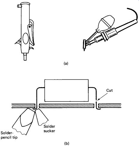
FIGURE 24-6 (a) Two types of manual solder suckers, (b) Removing a clinched
lead from the foil side.
Solder wick, which is nothing more than tinned shield braid, can be used to "sponge" up solder from a PC pad as an alternative to the solder sucker. Specially shaped soldering-iron tips are available to melt all the joints on a 16-pin DIP IC pack at once, but it is often difficult to melt all the joints without overheating one of them, and the old solder still must be removed so that the new component can pencil tip be inserted. Desoldering tips should not be used where the IC leads have been clinched, as the extraction force required could damage the PC pads.
Wire and Terminal Desoldering: When four wires are wrapped around a terminal it may be impossible to remove one of them without damaging all of them. Now the wisdom of leaving a service loop becomes apparent, for it is often best to simply cut all four wires as close to the end as possible, clean the terminal with the solder sucker, cutters, and long-nose, and re-terminate the wires.
24.9 SOLDERING ALTERNATIVES
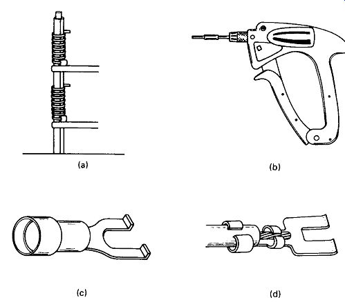
FIGURE 24-7 (a) Wire-wrap terminal, (b) Wire-wrap tool, (c) Solderless crimp
terminal, (d) Solder terminal with insulation grip.
Resistance Soldering: If a high current is passed through a small terminal, it will heat up from within and melt solder. There can be no possibility of the terminal being too cold to take solder with this method. A step-down transformer is used to provide the high current, which is applied through needle-point or carbon-tip probes. The probes must be held firmly to the terminal before the transformer primary switch (usually a foot switch) is closed and may not be removed until the primary switch is opened. Breaking contact causes arcing and pitting of the terminal.
Wire Wrap has become very popular for prototyping, one-of-a-kind instrument production, and printed-circuit-card socket interconnections. It is a solderless method for connecting solid-wire ends to special wire-wrap terminals, which are stiff square posts about 2 cm long with sharp corners. The wire is stripped several centimeters back and wrapped around the post six or more turns with a special wire-wrap tool. The pressure at the corners is sufficient to maintain reliable electrical contact in spite of vibration, moisture, and oxidation. As many as three wire terminations can be made to one post, and posts are commonly spaced on 0.1-inch centers.
Figure 24-7(a) shows a wire-wrap connection.
Terminals: Solder-type and solderless crimp-type terminals are shown in Fig. 24-7. They are suitable for either solid or stranded wire. Many terminals have a second wrap-around tab which is meant to be crimped lightly around the insulation to prevent flexing of the wire at the point of the stripping cut. With solder-type terminals the insulation should be held away from the terminal during soldering to avoid melting it.
-----------------