
By J. A. "Sam" Wilson, CET
Another electronic field that's expanding at a phenomenal rate is "industrial electronics". Many technicians each year are changing from TV or audio servicing to begin working with industrial equipment. There even is an "industrial" option for the Certified Electronic Technician (CET) test from NESDA/ISCET. In this series, we will explain the components and typical circuits used in present-day industrial electronics equipment.
It would be helpful if we could give a clear and accurate definition of "industrial electronics", including what it is and also what it is not. Unfortunately, we can't precisely set the limits of any electronic area, because the various fields are interwoven tightly.
Suppose, for example, we defined industrial electronics as "the applications of electronic principles in industry". That definition would include intercoms, telephone systems, television, tape/disc recording and playback, computers, and a host of other devices which are so important that they rate a category of their own.
On the other hand, if you try to narrow the definition by calling it a "study of the use of electronic principles in control systems", you automatically include garage-door openers and remote-control television tuners.
My point is this: any complete study of industrial electronics should cover some subjects that sometimes are included in the more conventional electronic subjects.
For example, we will emphasize control systems, logic- and computer-circuitry measurements, and processing. As a bonus, the series also will include the type of information that is needed for you to pass the Industrial Electronics CFT test.
Control-Systems Hardware
Solid-state components have changed completely the kind of "hardware" that is used in control systems. Earlier circuits for controlling industrial machinery had "thyratron" and "neon" tubes.
Thyratrons are gas-filled triode tubes which are capable of switching large currents. SCRs are the solid-state equivalents of thyratrons.
Neons are gas-filled cold-cathode diodes that have a "breakover" characteristic. In other words, no current flows until the voltage exceeds a minimum critical value.
Three-layer diodes, called "diacs", and the modern solid-state equivalent.
Integrated circuits (ICs) have made possible giant changes in the design and capabilities of industrial electronic systems. However, not all of these systems employ ICs. For example, the control circuits manufactured by Versaframe (see Figure 1) have discrete (separate and distinct) components, including transistors, diodes, and resistors. In ICs, all of these components would be in a single small package. However, we won't omit vacuum tubes, for many rugged items of equipment still use them.
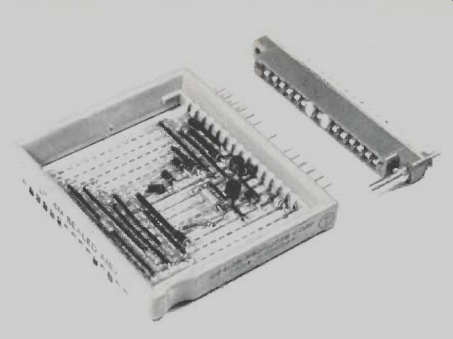
Fig. 1 Some wired logic modules have discrete components. (Courtesy
of Versaframe Division of Design Products)
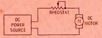
Fig. 2 A power rheostat is the most simple controller of DC-motor speed.
Motor speed and power depends primarily on the current.
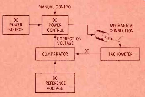
Fig. 3 A closed-loop analog system can control the speed of a DC motor.
Faster shaft rotation produces a higher positive voltage from the tachometer,
and this variable voltage is compared with a fixed DC reference voltage.
Wrong motor speeds cause a positive or negative correction voltage from
the comparator, and it adjusts the power-control circuit in the direction
needed to restore the correct motor speed.
Basic Controls
Although industrial electronics includes many other important subjects besides control systems, such systems are used extensively in many applications. Usually they are the "open-loop" type, or the "closed-loop" controls. To compare the two systems, we will use block diagrams for the speed control of DC motors.
Open-loop controls
As shown in Figure 2, the speed of the DC motor is dependent upon the armature current. A variable resistor (wired as a rheostat) controls the amount of current.
This is an example of open-loop control, because following the setting of the rheostat, there is no direct control of the speed. If the load on the motor changes, so will the shaft speed.
Closed-loop controls
One example of a closed-loop speed-control system is given in Figure 3. This system is not necessarily the best one for regulating motor speed, but it does illustrate the principles that are involved.
First, a manual adjustment sets the armature current to the desired value, which should provide the approximate speed. Motor speed is sensed by a tachometer which, in this example, has a DC output voltage that is proportional to the motor speed. Faster motor speed develops a higher DC voltage.
The variable tachometer voltage is compared to a non-varying (reference) DC voltage. When the two voltages are equal, it is assumed that the motor speed is normal, and no correction is needed.
If the motor speed changes, a correction voltage (that is proportional to the error) is fed to the control circuit. The correction voltage restores the motor speed.
Closed-loop speed-control systems continually monitor the motor speed, and correct it when it is slow or fast. Sometimes these systems are called "continuous", to indicate control at all times.
Closed-loop systems of this type require a sensor for measuring the speed, comparators for determining the relationship of the DC voltages, amplifiers, power supplies, and other refinements. Although such analog systems can be designed to hold the speed fairly well, digital closed-loop systems usually have better control and are more efficient.
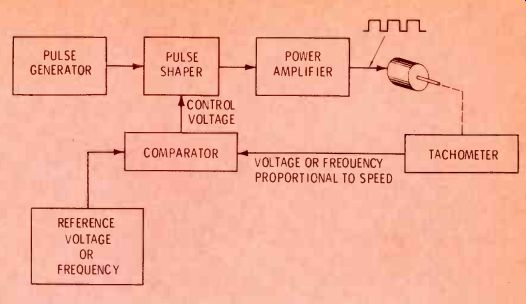
Fig. 4 Digital control of DC motor speed changes the width of the pulses
of DC voltage.
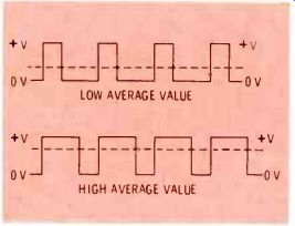
Fig. 5 Narrow duty-cycle pulses (above) have a low average voltage,
while below are shown wide duty cycle pulses that have a high average.
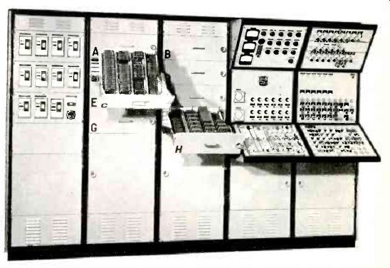
Fig.
6 A large industrial electronic system can simultaneously. Although each
control circuit might of control many functions be fairly simple, the
total all controls make up a very complex system. (Courtesy of Versa
frame Division of Design Products)
Digital closed-loop systems
The block diagram of a closed loop digital system for controlling the speed of a DC motor is given in Figure 4.
First, we must understand that a DC motor, which normally runs on continuous voltage and current, will operate at a slower speed, if the electrical power is applied intermittently. For example, you can slow a motor by switching the power on and off rapidly. This essentially is the method for digital control, although it is called "pulsed" DC current.
In Figure 4, the motor speed is sensed, and the error voltage used for control is returned to the pulse circuitry, where it determines the "duty cycle" of the pulse generator and shaper. In other words, it varies the "on" time versus the "off" time of the DC-voltage pulses.
Motor speed depends on the average DC current. Figure 5 shows how the average current value is affected by the width (duration) of the pulses of current.
Control summary
The three simple examples of motor control prove that such circuits can be rather complex.
Further, the control systems become much more extensive and sophisticated when they are designed to control other machine operations and even whole processes. However, these controls are only one type of industrial electronics.
When many additional functions are added, the resulting system (see Figure 6) can be extremely complex and sophisticated. That is all the more reason to study and understand the individual circuits.
Transducers
If you need to control the speed of a motor or the temperature of an oven (or any other industrial functions), you must have the right kind of "transducer" to determine the state of the system being controlled.
For example, you can't control the speed of a motor unless you can measure how fast it is running.
Transducers (sometimes called sensors) have been defined as devices that convert energy from one form to another. Of course, that is not possible (except for a few rare exceptions, such as the atomic bomb). To be precise, a transducer is a device permitting the energy of one system to control the energy of another system.
A common example of a transducer is a loudspeaker, where the electrical energy controls the sound energy. Also, microphones use sound energy to control the amount of electrical voltage or energy.
Passive and active transducers
Usually, two basic types of transducers are used in industrial electronics. "Active" transducers generate a voltage (or current), while "passive" ones do not. (Purists say that current can't be generated; only voltage can be generated, and current results when the voltage reaches a resistance. That's true.
But to save time and space, we'll continue to call it generated current.) Passive transducers usually change the resistance, capacitance, or inductance in a circuit according to some change of the input energy.
Active transducers generate a voltage or a current that is proportional to the amount of input energy.
Generating a Voltage
There are six basic methods of generating a voltage, but not all of these ways are used in active transducers. The following is a brief review of the six methods.
Electrostatic voltage
When two different types of insulating materials are rubbed together, electrons can leave one surface and cling to the other. This makes a voltage difference between the two materials. It is called an "electrostatic" voltage.
Electrostatic generators easily can produce large amounts of voltage, but their current capacity is very limited. Electrostatic voltage can be used in a precipitator of dust or smoke particles, but the electrostatic principle is too inefficient for use in transducers.
Chemical voltage
A voltage can be generated chemically between two pieces of dissimilar metal that are immersed in an acid or alkaline solution.
Auto batteries are one obvious example. However, the method does not lend itself readily for use in transducers.
Photoelectric voltage
Photoelectric transducers often are used for converting light to electricity or electricity to light. Such "optoelectronic" devices are employed extensively in industrial electronics.
--------
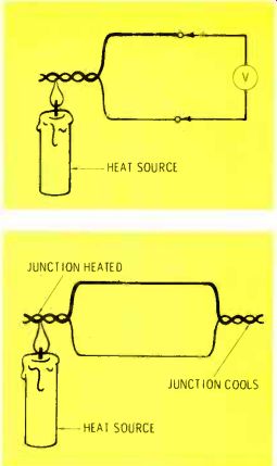
Fig. 7. Voltage is produced by the Seebeck effect when the junction of
dissimilar metals is heated.
Fig. 8. The Peltier effect cools the opposite junction of two dissimilar metals when the first junction is heated. Cooling by this effect now is practical.
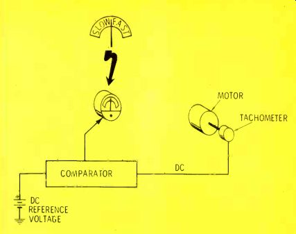
Fig. 9. A slow-fast speed meter uses some of the principles of Figure
3, except the relative speed is measured by the meter, and there is no
automatic control.
---------
Thermoelectric voltage
A voltage proportional to the amount of applied heat is the output of thermoelectric transducers.
There are two basic thermoelectric effects that you should know about. One is the "Seebeck" effect (see Figure 7). Whenever the junction of two dissimilar metals is heated, a DC voltage is available at the two ends. Some metals produce a voltage so small that it's barely measurable. Others can generate a useable amount of voltage. Some furnace safety controls operate this way.
Another thermoelectric phenomena is called the "Peltier" effect, as illustrated in Figure 8. When the junction of two dissimilar metals is heated, the opposite junction becomes cooler. For years, this was merely a lab curiosity, because the amount of cooling was small. However, refrigerators now are being made with Peltier-effect cooling.
Piezoelectric voltage
Certain crystalline materials will generate a voltage when their shape is changed. Quartz and barium titanate are two examples of piezoelectric materials. Rochelle-salts crystals and ceramic materials have been used in phonograph cartridges.
This effect is reversible. If a voltage is applied to a piezoelectric surface, the shape of the material will change.
Electromagnetic voltage
According to Faraday's law, when there is relative motion between a conductor and a magnetic field, a voltage will be produced in the conductor. The amount of voltage depends on the speed of their movement relative to each other, the strength of the magnetic field, and the number of conductors (turns of wire in the coil). AC and DC generators both operate by this principle. Many industrial transducers are electromagnetic in nature.
One application of an electromagnetic transducer is the tachometer shown in Figures 3 and 4. A tachometer converts the speed of rotation into a voltage, a current, or a frequency.
Figure 9 shows how a tachometer with a voltage output can be used to sense motor speed. The voltage is directly related to the speed of rotation (faster speeds produce higher voltages), and it is compared to a reference voltage. When the motor speed is too fast, the tachometer DC voltage is more positive than that of the reference, and the comparator will have a positive error-correcting output voltage. But, if the speed is too slow, the tachometer voltage is lower than the reference voltage, and the comparator output voltage will be negative. Correct motor speed gives the same comparator and reference voltage, so the comparator output voltage will be zero.
A zero reading of the zero-center meter indicates correct speed.
The meter readout of Figure 9 is said to be an "analog" type, because the pointer deflection is "analogous" to the motor speed. A digital readout would display the actual motor shaft speed in the number of revolutions per minute.
Comments
Part 1 has defined some basic industrial electronic terms. Also, the range of subject matter that will be covered in this series has been explained.
Next month, passive transducers will be examined, along with a review of basic (but often misunderstood) principles of inductance, capacitance, and resistance.
(adapted from: Electronic Servicing magazine, Jul. 1977)
Also see: Part 2