By J. A. "Sam" Wilson, CET
Passive transducers undergo a change of resistance, capacitance, or inductance when the energy level being sensed changes. For example, we learned that most thermistors have a decrease of resistance when their temperature increases. Other passive transducers are described this month.
Many transducers used in industrial-electronic devices vary their resistance in response to a change of the energy being monitored. Here's how they work.
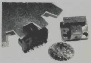
-------- At the left, a Hall-effect transducer senses rotation of
the vanes. The sensor at the right shows the two halves, with a powerful
magnet on one side and an IC on the other. The vanes block most of the
magnetism when they are between the halves. Hall-effect sensors can detect
very slow counts (where magnetic devices are useless); that is their
main advantage. This unit is rated from zero to 100,000 counts per second.
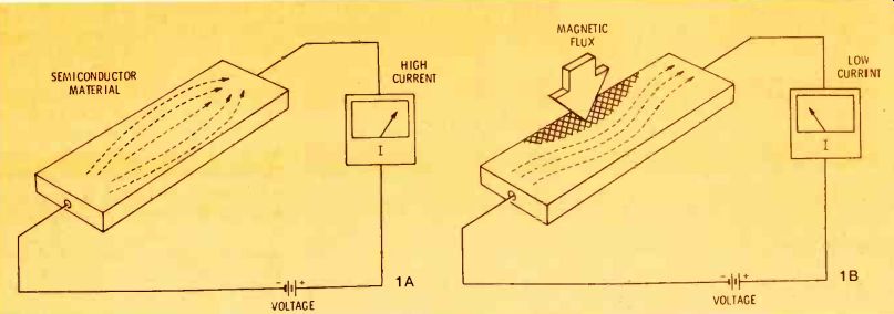
Figure 1 DC voltage applied to a slab of semiconductor material (A)
causes paths of the charge carriers (electrons) to be distributed evenly
throughout. (B) When a magnetic flux is applied to one edge, the charge-carrier
paths are reduced near the flux and are bent around the area. This is
the magnetoresistive effect.
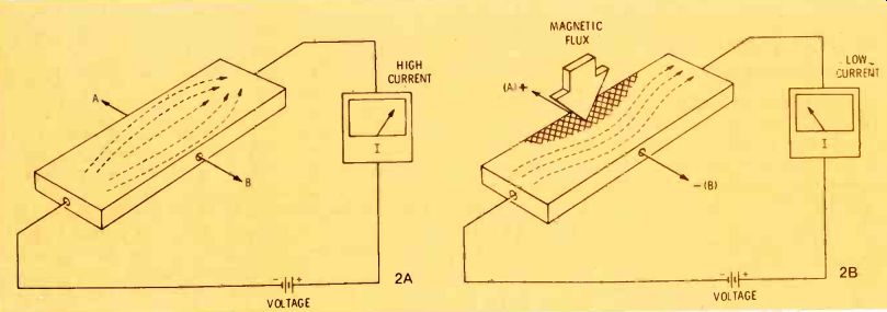
Figure 2 (A) Without flux, electrodes at A and B receive no voltage
when the semiconductor passes current. As in Figure 1, the current paths
are distributed evenly. (B) When a magnetic flux is applied to one edge
of the slab, a VOLTAGE, voltage is developed between the electrodes;
A is positive and B is negative. This is the Hall effect, and it is used
extensively in industrial transducers.

Figure 3 (A) Insulated plates mounted at the edges of the semiconductor
slab don't affect the current paths when no voltage is applied to them.
(B) Voltage connected to the plates decreases the number of current paths
near the negative plate thus reducing the current. This is the field
effect, which '+s the basis for Field-Effect Transistors (FETs).
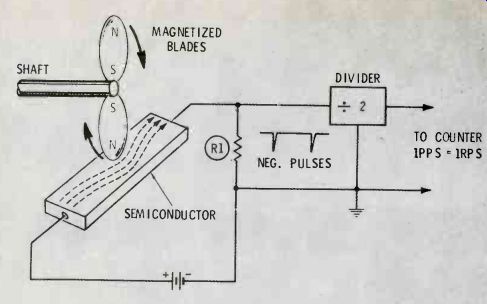
Figure 4 Rotating magnets reduce the semiconductor current as they pass.
Negative-going pulses of voltage are produced across the load resistor
R1. A divider equal to the number of magnets makes the output signal
directly indicate the shaft rotation per second.
Changing the Resistance
One or more of the following conditions must change before the resistance of a conductor or a semiconductor can be varied: Cross-sectional area. Lower resistance requires a larger cross-sectional area of the material.
Length. Longer paths for the charge carriers increase the resistance.
Temperature. PTC materials increase resistance with an increase of temperature, while NTC materials decrease resistance with an increase of temperature.
Type of material. Individual formulas for conductors and semiconductors produce materials having different resistances.
Notice, as we discuss some examples of resistor transducers, which of these four conditions is changed.
Cross-Sectional Variations
Physically changing the cross-sectional area to obtain a variable resistance usually is not possible or desirable. But, the same effect can be produced electronically.
For example, Figure 1 shows a slab of semiconductor material that's connected across a source of voltage. Arrows show typical paths of the charge carriers (Figure 1A), and you will notice that they are spread evenly across the material.
(These charge carriers are electrons.) However, when a magnetic flux passes through the slab (Figure 1B), the paths of the charge carriers move to the outside, around the flux. The result is less current, because the resistance has been increased by a reduction of the effective cross-sectional area. Stronger magnetic flux minimizes the current even more.
This is called the magnetoresistive effect.
The Hall Effect
The setup of equipment in Figure 2 is similar to that for demonstrating the magnetoresistive effect. However, two extra terminals (A and B) have been added to the semiconductor material.
In Figure 2A, when current is passed through the semiconductor, no voltage is developed at A or B. But the addition of a magnetic flux at the edge of the semiconductor (Figure 2B) warps the paths of the charge carriers, with few around A and many around B. Therefore, terminal B measures negative in respect to terminal A. In other words, a voltage is generated when flux is present. That characteristic makes it an "active" transducer.
This phenomena is called the "Hall" effect, and it's interesting to know that it was first discovered in 1879, although modern semiconductor techniques are required to make practical use of it.
Hall generators are used extensively as sensors for the measurement of magnetic field strength, and as sensors of shaft rotation or for counting in industrial electronic systems.

------ Figure 5 Most variable resistors change resistance by an adjustment
that selects a different length of the element.
The Field Effect
Another important principle called the "field" effect needs an explanation at this point.
In the absence of an electric field between terminals A and B of the semiconductor slab in Figure 3A, the electron-current paths are evenly distributed, and the current is maximum.
When a positive voltage is connected to B and the negative end to A, the electron-current paths are concentrated around B and they avoid the area around A. Therefore, the semiconductor current is reduced.
Experienced TV technicians will recognize the principle behind Figure 1 as being similar to magnetic deflection of a picture tube, while the electrostatic deflection of a scope tube is illustrated by Figure 3.
And, of course, this also is the way Field-Effect Transistors (FETs) operate.
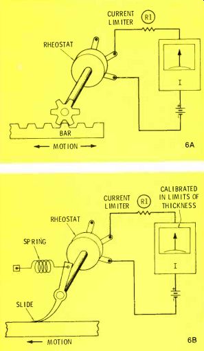
Figure 6 Rheostats and potentiometers can be attached to metal linkages
so the lateral position (A) or the thickness (B) of a moving object can
be read from the meter.
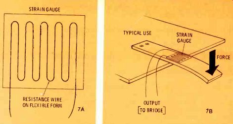
Figure 7 Resistance of a strain gauge changes when the device is bent.
(A) shows how the wire is applied to the paper backing, and (B) gives
one application whereby the strain gauge senses the bending of the beam.
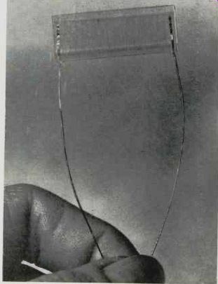
-------- Although this sensor has the appearance of a strain gauge,
it actually is a nickel iron-wire temperature sensor that's designed
to be embedded inside a heated aircraft window. (Courtesy of Minco Products)
Speed Measurements
The speed of shaft rotation can be measured by the magnetoresistive effect, as shown in Figure 4.
Both fan blades are magnetized (or two bar magnets are used for other applications). Every time a blade passes close by the semiconductor slab, the current is reduced. Therefore, negative-going pulses are developed across load resistor R1.
When a divide-by-two circuit is added to the output pulses, the pulses-per-second equal the shaft revolutions-per-second. (A four bladed fan, or four magnets, would require a divide-by-four circuit.)
Varying The Length Of Current Path
Most variable resistors (potentiometers, rheostats, or variable voltage-dividers as shown in Figure 5) are designed to change the resistance by a variation of the length of the resistive element.
Measuring lateral position or thickness Lateral position of an object can be monitored by connecting a rotary rheostat with rack-and-pinion gears (see Figure 6A). The motion of the bar turns the shaft of the control (thus varying the length of the resistive element), and the resulting current is read on the meter. This circuit works best with slow-speed movements. Also, it has memory, so stoppage of the bar movement is indicated.
Calibration of the meter scale shows the desired position plus any permissible deviation, and the meter can be mounted separate from the machinery to provide remote readings.
Figure 6B illustrates one method of monitoring the thickness of a moving object (such as lumber or insulation for homes). A slider bracket attaches to the shaft of a rotary potentiometer or rheostat, and a spring holds the slider against the plate or moving object.
In this case, increased thickness causes more resistance and a lower reading on the meter. The meter scale can be marked in inches or with high and low tolerance readings.
Strain Gauges
When force is applied to a solid mass, bending or deformation occurs. Stress is the force that's applied to a physical body, and strain is the resulting change of shape.
Therefore, a strain gauge is used to measure the deformation that results from stress. A typical strain gauge is illustrated in Figure 7.
Small-diameter resistance wire is fastened securely to a non-rigid backing material, such as paper or plastic. When the device is bent or twisted, the length of the wire is increased, and the stretching of the wire makes it thinner (reduces the cross-sectional area). Both of these effects increase the resistance. (This change is not large compared to that of thermistors or varistors, and usually requires amplification or use in a bridge circuit to increase the sensitivity.) Although Figure 7 shows the strain gauge measuring the bending of a beam that's under stress, the bending of any material can be detected.
Resistance Versus Temperature
Thermistors are resistive transducers that undergo a relatively large change of resistance when its temperature is varied. This was discussed at length previously. One of the applications was an alarm that signaled when a tank was empty.
Although the schematic was similar to Figure 8, the principles are different. Last month, the self-heating effect of a thermistor changed according to whether or not it was in the liquid. Conductivity of the liquid was not a factor. Compare that with the next description.
Transducers That Change Material
A simple example of a sensor that utilizes a change of material is shown in Figure 8. In this case, the liquid in the tank has a low electrical resistance. At normal liquid depths, the A and B electrodes are separated by air, a good insulator. When the liquid is overfilled and rises above the electrodes, the conductive liquid completes the circuit and activates the alarm relay. The normally-open pair of relay points are used for this kind of alarm.
For an empty-tank alarm, the electrodes are placed at the bottom.
When the tank is full, the electrodes are in the liquid, thus activating the relay all of the time. A low level of liquid exposes the electrodes to the air, the relay opens and lights the warning through the normally-closed points.
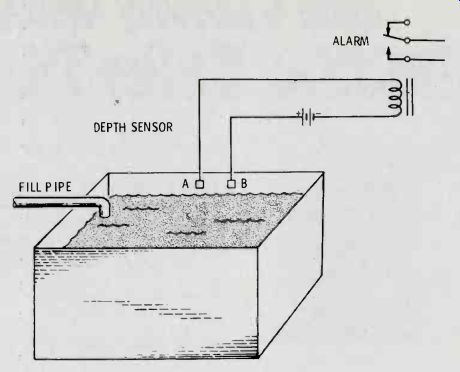
------- Figure 8: Some sensors depend on a change of material for a signal.
In this example, the liquid readily passes electrical power, and the
circuit can be arranged to show overfilling or an empty tank. When
the electrodes are in air, the relay has no power. Then, when they
are immersed in the conductive liquid, the relay coil is energized.
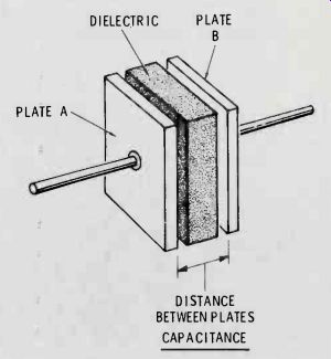
Figure 9 The factors that determine capacitance are shown here.
Capacitor Parameters
A capacitor stores energy. Physically, it consists of two conductors that are separated by insulation (usually called dielectric), as illustrated in Figure 9.
The capacitance (or capacity) is a measure of how much energy a certain capacitor can store. These three factors determine the amount of capacitance: the areas of the plates that face each other. Larger areas produce increased capacitance; the distance between the plates.
The capacitance is inversely proportional to the distance between the plates. In other words, the capacitance is decreased by a wider separation of the plates; and the type of material that's used for the dielectric. The "dielectric constant" rates various materials relative to a vacuum.
It is important for us to understand that the energy of a capacitor is stored in the dielectric, and a vacuum is a poor storage unit; most materials are much better. Thus, the dielectric constant predicts how much more energy the various materials can store compared to a vacuum.
The equation for capacitance is: Capacitance equals the plate area divided by the distance, times the dielectric constant (K). Capacitance transducers must vary either the plate area, the distance between plates, or the material of the dielectric.
Next Month:
Capacitive transducers and some of their typical applications will be the main topic next month.
(adapted from: Electronic Servicing magazine, Sept. 1977)
Also see: The Basics of Industrial Electronics, Part 4 (Oct. 1977)
The Basics of Industrial Electronics, Part 1 (Jun. 1977)