By J. A. "Sam" Wilson, CET
A capacitance transducer undergoes a change of capacitance when the condition of the material or process being monitored becomes different. These capacitance changes can be accomplished in one of three general ways.
The factors that determine the capacitance of a capacitor are: the area of the plates; the distance between the plates; and the type of dielectric between the plates.
Temperature often affects the capacitance. But, in most applications, the temperature coefficient is listed as a disadvantage that must be overcome.
Any of these three factors can be made variable in transducers that change capacitance to indicate a different condition of the material being tested.
Varying the Distance
Condenser microphone
One example of a capacitive transducer that operates by varying the distance between the two plates is the "condenser" microphone. Of course, the word condenser in electronics has been replaced by capacitor. However, this type of microphone was developed in the 1920s, and the old name persists.
Operation of a condenser mike does not vary the applied voltage or the dielectric, but it changes the capacitance by changing the distance between the plates (see Figure 1). The formula for the charge on a capacitor (called Q) is:
Q = C x V.
Therefore, when the voltage is held constant, any change of capacitance results in a corresponding change of the charge. For example, an increase of capacitance increases the charge; or a decrease of capacitance decreases the charge.
One plate of the capacitor in a condenser microphone is rigid, while the other is a very-thin and flexible diaphragm that's clamped at the edges but free to vibrate at the center (Figure 1). Sound waves striking the diaphragm move it alternately closer or farther away from the back plate, changing the capacitance. The charge varies in step with the capacitance. Increased capacitance requires more current, while reduced capacitance has less current flow. When a load resistor (R1) is added is series with the charging current, the sound waves cause a varying voltage drop, which is the electronic equivalent of the sound waves.
In practice, the change of capacitance is very small, and the output voltage is extremely low. To raise the level so it's equal to that of other types of mikes, a preamplifier usually is mounted near the capacitance unit. The diaphragm must be mounted very close to the back plate, to give the highest possible output signal, and when it is stretched tightly to raise the resonant point above the range of hearing, the frequency response can be much flatter than the response of dynamic or ceramic mikes. This is the value of a condenser mike, and the improved response is worth all of the extra components.
Vibration transducer
The same principle of movable plates is used with capacitive transducers that are designed to sense vibrations. One example is illustrated in Figure 2. It is built to endure strong pressures and is ruggedly constructed, in comparison to a condenser mike, which is very delicate.
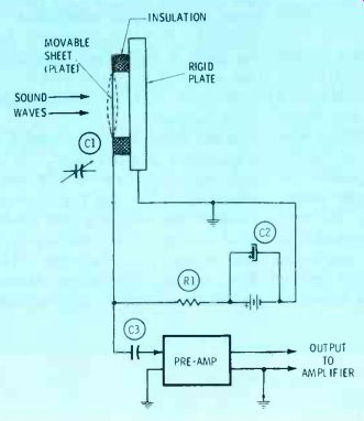
Figure 1 In a condenser microphone, sound waves move the flexible plate,
varying the spacing of the plates, and producing a variable capacitance.
The changing capacitance requires a varying charging current, which in turn causes a varying voltage drop across the load resistor, R1.
Thickness transducer Figure 3 shows another type of transducer that varies the distance between the capacitive plates to detect deviations of thickness. The dielectric is the material being tested for thickness, and therefore it must be a nonconductor such as rubber, linoleum, or other similar substance.
The capacitance is part of an oscillator circuit, whose frequency shifts with capacitance changes.
Frequency of the oscillator is adjusted with sample material of the desired thickness so it produces a minimum reading after the signal passes through a notch filter. Any change of thickness and its resulting change of frequency moves the signal up the sides of the notch, increasing the amplitude. The sensitivity is adjusted for the amplitude of signal produced by the maximum allowable deviation from the desired thickness, and the control action or the alarm is activated for variations that exceed the tolerance. For example, the relay contacts might be used to stop the movement of the material until the problem was corrected. Or it could light a warning sign.
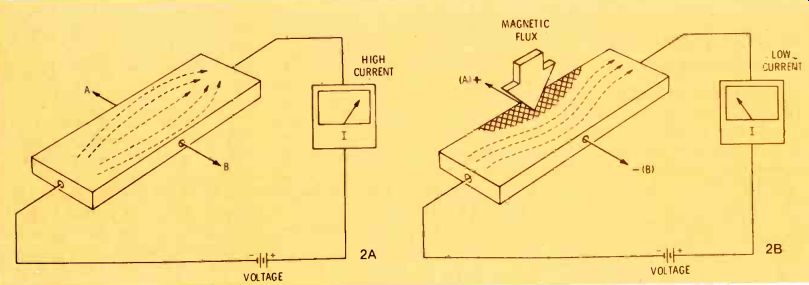
Figure 2 A capacitive vibration transducer is similar in principle to
a condenser mike, but it is built much stronger to withstand the heavy
blows.

Figure 3 Two metal plates held against top and bottom of a moving piece
of insulating material in a manufacturing plant change capacitance according
to the thickness of the material. Thus, thickness variations change the
oscillator frequency, and an unacceptable thickness moves the frequency
out of the notch. This increased amplitude can trigger a relay or a warning
device.
Figure 4 Here are two versions of a capacitive depth indicator. (A)
When the liquid is between the plates that act as a capacitor, the capacitance
is increased, and the stronger current trips the relay to sound an overfill
warning. Lower liquid levels provide only air between the plates, and
the weak current is not enough to trip or hold-in the relay. (B) A more-sophisticated
version uses longer capacitor plates, an amplifier for sensitivity, and
a meter than can be calibrated in gallons or depth. More plate area with
the non-conducting liquid between gives increased capacitance; thus passing
more voltage to the meter, and giving a continuous reading of depth.

Figure 5 Capacitive bridges have a sharp null at the balance point.
Output AC signals from the bridge can be amplified to provide good sensitivity.
Bridges are very useful when the capacitance change is not large.
Figure 6 Here is one example of an AC-bridge circuit that's used in
industrial electronics. When the production-line metal item is positioned
exactly between the C1 and D2 plates, two equal capacitors are formed.
This balances the bridge, and the AC output has almost zero amplitude. If the metal object is positioned wrongly, one capacitance will be larger, and the other smaller. Thus, the bridge is unbalanced, and the output rises sharply. If the output increases above a preset point, an auxiliary circuit can flash a warning sign or prevent the next automated step of the production machinery.
Figure 7 Electrostatic transducers closely resemble some capacitance
types. In some ways, operation of this ultra-sonic generator is opposite
to that of the condenser mike in Figure 1. Both have a DC polarizing
voltage, but the mike accepts acoustic sound waves and produces an electrical
audio signal, while the generator uses an AC electronic signal that's
similar to audio (but higher in frequency) to produce super-sonic acoustic
sound waves. Some models have a tuned horn to strengthen the signal level.
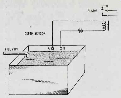
Figure 8--The action of capacitors when taking or discharging power
is quite complex. This simplified explanation should help you understand
the basic principle. Imagine that dielectric material is composed of
many tiny "dipoles" (as shown in A) of random orientation.
When a capacitor accepts a charge, the dipoles arrange themselves as
drawn in B. Reversing the polarity of the charge (C) also reverses the
dipoles. Heat from friction is produced during the movement of the dipoles,
when an AC charge is applied to the capacitor.
This is the reason for the dielectric-heating phenomena.
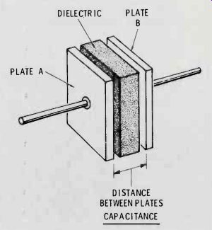
Figure 9 Here is an experiment you can perform to prove that the charge
of a capacitor is held in the dielectric. Make a capacitor from two metal
buckets and one of dielectric material, assembled one inside the other
(A). Charge the capacitor to a high voltage. Then, using insulating sticks,
remove the dielectric pail, and short together the two metal buckets
(B). Such a short would remove or dissipate any charge held between these "plates." Assemble
the components again, as shown in C, and carefully connect a shorting
bar to the two metal buckets. Before or during the contact, you should
see an arc, proving that the original charge was there, even after the
disassembling and efforts to discharge.
If the notch filter is replaced by a zero-center discriminator, the circuit then can indicate whether the material is too thick or too thin.
Further, the output signal could be used to control the mechanism that determines the thickness. Therefore, any out-of-tolerance thickness would be corrected automatically.
Varying The Dielectric
The level of fluid in a tank can be sensed by a capacitive transducer, as shown in Figure 4. Of course, the liquid must be a non-conducting type, and it's desirable for it to have a high dielectric constant.
When the liquid level is low, the dielectric is air and the capacitance is low also. At higher levels, the liquid becomes the dielectric, increasing both the dielectric constant and the capacitance.
Two different indicators are illustrated. The first sensor is not very sensitive. Air is the dielectric at normal depths, and the current is not sufficient to close the relay. At the overfill point, the increased capacitance from the change of dielectric increases the current, closing the relay points. The second circuit indicates any depth by the amount of AC voltage that passes through the capacitance. In fact, the meter can be calibrated in gallons or the depth in feet.
Capacitive Bridges
Capacitive transducers often produce a very small change of capacitance, and need amplification to make the change sufficient for a reliable reading. Or, an undesirable temperature coefficient might cause excessive drift. Both of these corrections can be made in an AC bridge circuit (Figure 5). This bridge is balanced when C1/C2 equals R1/R2. In other words, when the ratio of the capacitances equals the ratio of the resistances. At the balance point, the output AC voltage is minimum.
Position sensor
One use for a capacitive bridge is shown in Figure 6. Two separate capacitances are formed by the plates and the grounded metal object. When the object is centered correctly, the two capacitances are equal, and the bridge is balanced (giving a minimum-amplitude output AC signal). If the object is not centered, the capacitances are not equal, the bridge is not balanced, and the output signal has a comparatively strong amplitude.
This output signal might be read on a meter marked with in-tolerance and out-of-tolerance areas. Or, the amplified output signal could activate a safety circuit that would not allow a subsequent step to occur unless the bridge was balanced.
The balanced-bridge transducer operates by varying the active area of the plates, according to the position of the object. Remember that only those areas facing each other contribute to the capacitance.
Electrostatic Transducers
Closely related to the capacitive types are the electrostatic transducers. One example is given in Figure 7. The ultrasonic generator (frequency above 20 KHz) has a fixed plate and a movable plate.
A DC voltage is connected between the plates, placing a negative voltage on one and a positive voltage at the other. Unlike charges attract, and like charges repel, so the voltage produces a small attraction between the plates.
An AC voltage source is wired in series with the DC voltage. When the positive peak of the signal is at the positive plate, the attraction between the plates is increased.
Similarly, when the negative peak of the signal is at the positive plate, the attraction between the plates is decreased. Therefore, the movable plate vibrates in front of the rigid plate, producing a sound wave.
One use for an ultrasonic generator is to agitate a liquid which shakes loose the dirt and grease from the inside of clocks or TV tuners. In addition, ultrasonic devices also are used for measurements, and in intrusion burglar alarms.
Dielectric Heating
The principle of dielectric heating can be understood by reviewing some little-known facts about the behavior of the dielectrics in capacitors.
Actually, the energy of a capacitor is stored in the dielectric. A physical change occurs in the dielectric when the capacitor is charged. Figure 8 shows a simplified version of what happens inside the dielectric material.
The dielectric can be imagined as being made of many tiny dipoles, each having a positive charge at one end and a negative charge at the other. In the uncharged state (Figure 8A), the dipoles are pointing in random directions.
When the capacitor is charged, the dipoles align with the electrostatic lines of flux, as shown in Figure 8B. If the polarity of the applied voltage is reversed, the dipoles also reverse direction (Figure 8C). A high-frequency AC voltage across the capacitor causes the dipoles to reverse direction rapidly in step with the positive and negative peaks of the waveform.
The reversal of the dipoles is opposed by friction, so heat is generated within the dielectric material.
Some frequencies of RF produce more heating effect than others do.
Dielectric heating is used extensively in industry to heat plastics and other non-conducting materials.
Electrostatic Pail Mystery
The theory of dielectric behavior just described explains the results of the experiment in Figure 9.
Three buckets or pails are inserted one inside the other (Figure 9A). The outside pails are metal, and the middle one is made of dielectric material. Of course, you recognize this as a capacitor.
The capacitor is charged with a very high DC voltage (say 1 million volts). Then the capacitor is disassembled, using insulated sticks (Figure 9B), and the two metal plates are stacked together (which shorts them together). If the charge actually is stored in the plates, it now will be gone. But when the pails are re-assembled (Figure 9C) and a shorting bar touched to the two metal pails, a large arc can be seen.
The dipoles were held in their previous alignment by friction; therefore, the charge remained in the dielectric, and when the capacitor was reassembled, the charge still was there.
This experiment proves that the charge of a capacitor is stored in the dielectric.
(adapted from: Electronic Servicing magazine, Oct. 1977)
Also see: The Basics of Industrial Electronics, Part 5 (Nov. 1977)
The Basics of Industrial Electronics, Part 1 (Jun. 1977)