
The basics of industrial electronics, part 17--In this last article of the series, Sam gives some practical and commercial examples of counters and digital displays.
-J.A. "Sam" Wilson.
A new series is scheduled for next month, so this is the final basic industrial electronics article. Sam gives examples and block diagrams of many practical counter applications.
Counting Circuit Examples
By J. A. "Sam" Wilson, CET
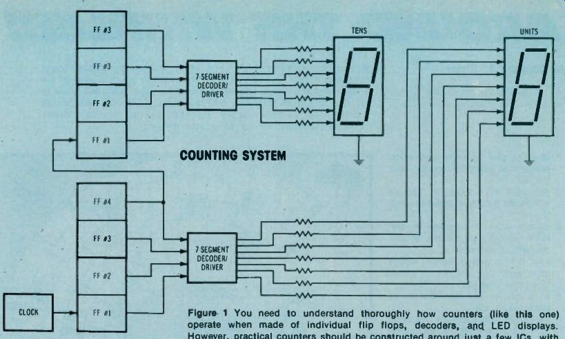
Figure
1. You need to understand thoroughly how counters (like this one) operate
when made of individual flip flops, decoders, and LED displays. However,
practical counters should be constructed around just a few ICs, with each
containing many sets of the essential digital gates.
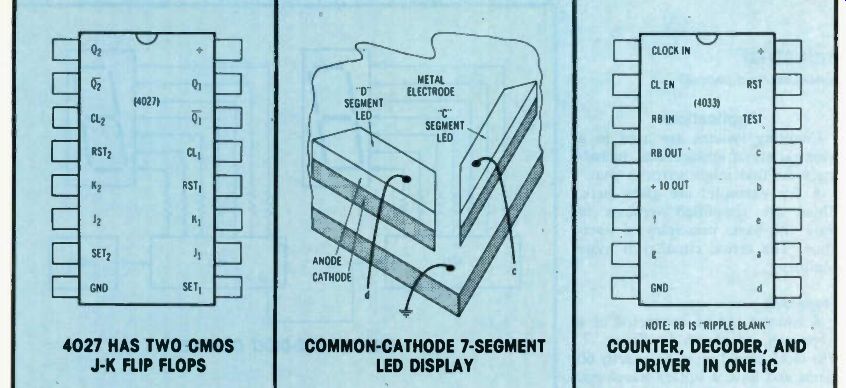
Figure 2. The 4027 CMOS IC contains two J-K flip flops. Two such ICs are
used for each digit of a counter.
Figure 3. Here is one way "common cathode" 7-segment LED displays are manufactured.
Figure 4. For more simplification, a 4033 CMOS IC includes the counter, decoder, and display drivers for one 7-segment digit. These can be cascaded for as many digits as desired.
Simplification of Counting Circuits
Counting circuits (such as the two-digit design of Figure 1) can be constructed easily, if you use ICs that have multiple gates. This saves much duplication of wiring, and minimizes mistakes. Four flip flops are needed for the units count, plus four more for the tens count. It would be time consuming to use individual flip flops. Worse yet is the thought of wiring individual flip flops from discrete transistors! A number of ICs have two flip flops in each DIP. For example, IC 4027 in Figure 2 has two CMOS J-K flip flops, which can be connected to toggle, as needed for the counter.
Decoder/Driver Circuitry
Separate decoders are used in Figure 1 for the units and tens counters. They are necessary for conversion of the binary-coded decimal (BCD) outputs of the flip flops into signals for lighting the appropriate sections of the 7-segment displays. Power for operating the LED segments comes through each decoder/driver. Therefore, each output either is high (near the supply voltage) or low (near zero). Of course, all LEDs require cur rent-limiting resistors, which usually are external to the ICs (as shown in Figure 1). These resistors are connected between the decoder/ driver IC terminals and the individual anodes of the LED display. All LED cathodes are connected together, and then grounded.
There are several basic ways of connecting the LED segments in side these displays. In Figure 3, each segment is made from long strips of anode and cathode material, with the cathode material in direct electrical contact with the metal that's bonded to the epoxy substrate. This automatically grounds all LEDs through the common ground plate, and only a "hot" wire connects to each anode.
Another type has three LEDs formed on each segment strip. These three LEDs are paralleled, and therefore they light together.
Each segment appears to be made up of three lighted dots during operation. Of course, different de coder/driver packages and different values of limiting resistors are required for these various types of displays. (Not all displays are of the "common cathode" type just de scribed. Others have all anodes connected to the positive side of the power supply at a "common anode" terminal. Each segment is lighted by grounding its cathode lead through a decoder/driver unit.) One-IC counter After you have wired simple counters from individual gates, and know how they operate, you should assemble practical counters from ICs that have all essentials (except the display) in one package.
The CMOS 4033 of Figure 4 has all of the counting, decoding and driver circuitry needed for one digit of a counter.
With IC 4033, the clocking signal for the count is delivered to the "CLOCK IN" pin-1 terminal, while the "4-10" terminal provides an output signal for clocking the next higher digit, if there is one. A proper signal at the clock-enable ("CL-EN") terminal can stop the count without interfering with the clock signal itself.
The count can be reset to zero by an input to the "RST" (reset) terminal, and the "RB" (ripple blank) terminal is used for blanking any undesired zeros at the display.
Lower-case letters ("a" through "g") mark the terminals intended for connection to a standard 7-segment display.
As shown in Figure 5, only two 4033s are required to construct a two-digit counter.
Interfaces Instead of LED displays, a de signer may choose a liquid-crystal display (LCD), incandescent lamps, or a gas discharge (neon lamp) type.
A decoder/driver intended for LED use probably can be used with these other systems if an appropriate interface device is added. This interface might be a single IC that's designed for the job. Another approach is the use of optical couplers.
Remember that an interface of some kind is necessary for operation of a component having a voltage, current, or power requirement of different rating than the logic-system output.
Figure 6 shows how an interface could be inserted between a counter and a gas-discharge display. TTL counters have outputs of about +5 volts, and CMOS usually have slightly more. This interface must accept an input of low voltage, and supply an output of 65 volts for the gas-discharge digits.
Applications
Counting systems are used in a wide variety of applications, including some that might surprise you. A few examples are given here.
These are simplified versions to show the basic principles of operation. The actual circuitry is more complex.
Stopwatch
A counter can be connected as a stopwatch, as shown in Figure 7.
The clock signal must be exactly 60 Hertz and have a square waveform.
It can be obtained by squaring 60-Hz sine waves from the power line, or it can be counted-down from a crystal oscillator of a higher frequency.
Counting of the stopwatch is started when the clock enable (CLK EN) terminal is pulled high. It's stopped by application of a low to the same terminal, and the display shows the number of seconds that have elapsed while the enable terminal was high.
A high applied to the reset (RST) terminal returns the display back to zero seconds.
Frequency counter
A modification of the previous schematic can change it into a frequency counter, as shown in Figure 8. The unknown frequency replaces the clock signal.
Some waveforms require a change to pulses or square waves to insure accuracy of count. Conditioning by the Schmitt trigger eliminates the problem.
The clock-enable terminal is held high for one precise second while individual cycles of the input signal are counted. Therefore, the readout shows the cycles-per-second (Hertz) of the input signal. Actual counters read and display the frequency continuously, and many have pro vision for a choice of several sampling times.
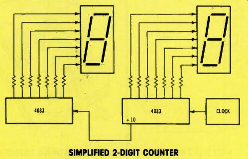
Figure 5. Two 4033 ICs can be wired as shown to provide a two-digit counter.
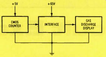
Figure 6. Other types of display can be used, if an appropriate interface
is added. Its input matches the counter, and the output must drive the display
with the voltages and currents that are needed.
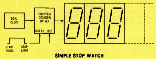
Figure 7. The least-significant digit (at the right) of this stopwatch reads
in tenths of a second up to 0.9. Three digits could read to 99.9 seconds.
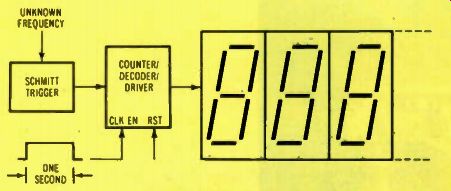
Figure 8. A counter that's sampled for one precise second will read directly
in cycles-per-second (Hertz).
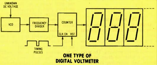
Figure 9. Frequency of a voltage-controlled oscillator is changed by the
unknown DC voltage, and a counter displays the frequency, but calibrated
in DC volts.
Digital voltmeter
Many different basic methods are used to measure DC voltages digitally. All require some kind of analog-to-digital converter. Figure 9 shows one method. (If the unknown voltage is AC, it first must be changed to DC.) Frequency of the voltage-con trolled oscillator (VCO) is determined by the amount of the unknown voltage. When the unknown is zero volts, the frequency divider counts the VCO output as 0 Hertz, and the display shows 0 volts.
A higher DC unknown voltage increases the VCO frequency, and the counter circuit is calibrated to read the DC voltage correctly.
Last of the Series
This article is the 17th and last of the series about basic industrial electronics.
The series began with studies about open-loop and closed-loop circuits, and the many types of transducers that sense conditions or locations. Later the emphasis was shifted to basic logic gates and circuits, since many of the new industrial systems have digital controls. During the past few months, the fundamentals of counting circuits were explored.
Next:
The next digital subject will be microprocessors, including the makeup of the systems, typical circuit operations, and some uses for them. Watch for our microprocessor series.
(adapted from: Electronic Servicing magazine, Nov. 1978)
Next:
Prev:
Also see: Sam Wilson's Technical Notebook