
by J. A. "Sam" Wilson
Sam Wilson's monthly "Technical Notebook" will present a variety of subjects and ideas. Sam has strong opinions, and possibly some will provoke conversation and controversy. The ideas and opinions of this column are not necessarily those of the editor or other employees of Electronic Servicing.
Your letters are welcome, so long as you give us permission to quote from them. Address all letters to:
J. A. "Sam" Wilson c/o Electronic Servicing
P.O. Box 12901 Overland Park, Kansas 66212, USA
Misleading Questions
One of my volunteer jobs has been to prepare questions for the International Society of Certified Electronic Technicians (ISCET) for testing those who want to become Certified Electronic Technicians (CETs). You'd think that it would be a simple matter to make up 75 questions designed to test broad areas of electronic knowledge. But, let me assure you, it's not easy. You can't take a course in school about test making, and you can't find a book that teaches the rules. So, at first I made some mistakes.
Very quickly, I learned that certain types of questions become traps for unwary technicians, causing them to mark a wrong answer to a question they understood fairly well.
For example, questions asked in a positive way (such as, "Which of the following determines the amount of current in the circuit?") produced many more correct answers. While negative questions ("Which of the following does NOT determine the amount of current in the circuit?") caused more wrong answers.
---------------
THE CAPACITOR IS CHARGED; WHEN THE PLATES ARE MOVED APART, WHAT HAPPENS TO THE VOLTAGE?
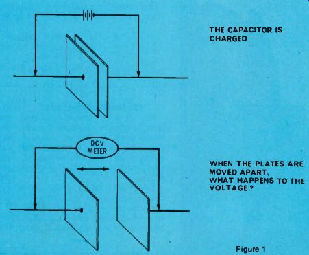
Figure 1
----------------
The subject matter also plays an important part in the final score.
Questions about capacitances and capacitors were more often missed than questions involving resistors.
When you know this before you make up a test, how do you decide on a reasonable number of questions about capacitors? These tests do not have "catch" questions, but are intended to evaluate the tech's all-round knowledge of the electronics field. Therefore, it's not desirable to include little-known facts or slanted questions.
I have a list of questions that have been answered incorrectly most often in the CET tests. Not all were made difficult by the exact wording of the questions. Some referred to new components, while others were about basic subjects that often are not understood completely. These 10 questions were not used in the tests, but are similar. The answers follow the last question. What was your score?
Question 1
The simple capacitor of Figure 1 is charged with DC from a battery.
After the capacitor is charged completely, the battery is disconnected and the plates are moved farther apart. Does this affect the capacitor voltage? If so, is the voltage larger or smaller?
Question 2
If you have been following the "Basics of Industrial Electronics" in Electronic Servicing, this next question will be easy to answer.
When three pails (or buckets) are stacked tightly together (an insulating pail between the two metal ones), they form a low-value capacitor (Figure 2). This capacitor is charged by about one million volts DC. The capacitor is disassembled (very carefully!), and the two metal pails touched together for a time.
When the three pails are reassembled in the original way, what is the voltage between plates X and Y?
Question 3
The next question brought me more "hate" mail than any other part of the CET test. An uncharged capacitor is connected to a battery, as shown in Figure 3. What is the voltage between terminals A and B? To make it easy, I gave only two possible answers. The voltage either is 100 volts, or it is zero volts.
Question 4 When technicians connect two capacitors in series, they should understand thoroughly the division of the voltages across them. The two capacitors of Figure 4 are connected in series across a battery.
Which capacitor has the larger voltage drop across it?
Question 5 Varactor tuners are old stuff now, so you should have no problem with the circuit of Figure 5. However, when the question first appeared in a CET test, varactor diodes were new to consumer products, and the question was difficult for the techs. To increase the capacitance of the varactor diode, should you move the arm of the variable resistor toward the positive point A, or toward the zero point B?
Question 6 This next question aroused the second-highest level of righteous indignation. In the tube circuit of Figure 6 (remember tubes?), an RF transformer has primary winding Li and secondary winding L2. Are C1 and L2 the components of a series-tuned or a parallel-tuned circuit?
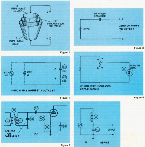
Figure 2 - Figure 6
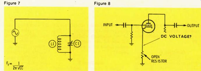
Figure 7; Figure 8

Figure 9; Figure 10
Question 7 Figure 7 shows a parallel-tuned RF circuit, with the capacitor made to be varied for proper tuning. In the dim days of old, two or three such variable capacitors often were operated from a common shaft.
Sometimes, to achieve better "tracking" with the other tuned circuits, the tech changed the spacing between the plates of one capacitor (by bending them sideways). When Hector was a pup, this was called "knifing the plates." Should the plates be moved closer together or farther apart to increase the resonant frequency?
Question 8 In the tube circuit of Figure 8, the gain and plate current of the amplifier stage have been cut off because of the open cathode-bias resistor. What approximate voltage should you expect to measure (with a VTVM) from cathode to ground?
Question 9 Frequently, this question is asked about a bipolar transistor, rather than the P-channel MOSFET shown in Figure 9. In this amplifier circuit, should point X be supplied with positive or negative voltage, for normal operation?
Question 10 The last question is so difficult that no one in a group of 20 technicians at a service seminar could answer it. Therefore, I decided not to use the question in any CET test.
You need a 100-picofarad capacitor with a temperature coefficient of N330. You have no N330 capacitors, but you do have all of the standard values with a negative temperature coefficient of N750. Also, you have all values in the NPO (negative-positive-zero) type.
How can you connect capacitors of these two different temperature coefficient ratings to produce 100 picofarad with N330? (See Figure 10.)
Answers to the 10 Questions
Answer 1. Moving the capacitor plates farther apart after it becomes charged increases the capacitor voltage. You must consider that voltage is a unit of work, not a unit of force. Physicists don't use the words "electromotive force" any more, for it is deceptive. Unfortunately, many schools continue to tell students that "the voltage forces the electrons through the resistance." That's totally wrong. When the capacitor is charged, the plates are attracted to one another because of the unlike charges. Moving the plates farther apart requires work, and the work expended must change something. In this case, it is apparent as an increase of voltage.
Parametric amplifiers employ this unusual characteristic of capacitors.
In a capacitive parametric amplifier, a signal is introduced across the capacitor. Then at the peak of the signal, the capacitor plates are moved apart, increasing the voltage between the plates, and operating the same as an increase of input signal. The trick is in moving the plates apart at just the right time.
It's done by using a varactor diode as the capacitance and increasing the reverse bias at the split second when the signal voltage reaches the maximum value.
Answer 2. When the pails are reassembled, the capacitor still is completely charged, and a large spark can be drawn between the metal pails. We are ignoring the possibility that part of the charge could leak into the air, for in a dry climate this loss is negligible. The reason behind this startling demonstration is that the energy actually is stored in the dielectric, not on the plates. Therefore, the charge is not disturbed when the disassembled metal pails are touched together. Physicists believe the charge is stored by the alignment of "dipoles" in the dielectric material.
(Refer to the detailed explanation in the October, 1977 issue of Electronic Servicing, pages 42 and 45.)
Answer 3. The voltage across terminals A and B is 100 volts DC. Remember that the capacitor is NOT charged; therefore, there is no voltage across it. To say it another way, the same voltage is at both ends of the capacitor.
This question is a stumbling block to most technicians, because they have been taught from models.
The students are told and retold that capacitors can't pass any DC voltage. Also, many are called "blocking capacitors." These are partial truths, but they neglect one important transient condition: a capacitor passes current UNTIL it becomes charged. (Remember the textbook voltage and current charging curves?) When technicians see the simple circuit, they assume automatically that the capacitor is blocking the DC voltage, thus making the output voltage zero.
The question was prompted by an experience I saw in a class I was teaching. One of the students was troubleshooting a television receiver, using a large capacitor as a probe. The lead at one end was resting against the palm of his hand, and he was probing around with the other lead. I warned him to be careful, but he explained that he couldn't get shocked because he was working in a DC circuit. At that second, he reached a hot point of the circuit, and jumped three feet from the floor when the shock proved to him that a capacitor could (and did under those conditions) pass a DC voltage for a time.
Answer 4. The larger voltage always is across the smaller capacitor. This is true regardless of whether the applied voltage is DC or AC. With the values given in Figure 4, C1 will have twice as much voltage as will C2. In other words, one-third of the power-supply voltage is across C2, and two-thirds of the voltage is across C1. (Two 600-volt capacitors don't add to 1200 volts, unless the capacitances are equal.)
Answer 5. The arm of the control must be moved toward the B (zero voltage) terminal to increase the capacitance of the varactor diode.
Moving the plates of a capacitor farther apart decreases the capacitance, and moving them closer increases the capacitance. In varactor diodes, increasing the reverse bias has the effect of moving the edges of the depletion region farther apart, thus decreasing the capacitance. To increase the capacitance, the reverse bias must be decreased, thus narrowing the depletion region of the varactor diode, and increasing the capacitance.
Answer 6. In this configuration, L2 and C1 are in series. Whether the same current flows through both components or not is the one condition that determines if a tuned circuit is parallel or series tuned.
The signal voltage for L2 and C1 is not introduced at their common ungrounded ends (if it were, the circuit would be parallel tuned). Instead, the signal comes from L1 to L2 by induction. Any signal induced inside a coil is considered to be in series with the cold end of the winding. Therefore, you can imagine the signal as coming from a small generator that's connected between the cold end of L2 and ground. Looking at it that way, L2 and C1 definitely are series tuned, as shown in the drawing of Figure 6B.
Answer 7. To increase the resonant frequency, the capacitance must be decreased. To decrease the capacitance, the plates of a capacitor must be moved farther apart. Refer to Figure 7 for the tuned-frequency formula. Notice that the capacitance is in the denominator of the fraction. To increase the frequency, it is necessary to decrease the value of the denominator.
Answer 8. The positive voltage at the cathode of the tube will be very high, possibly as high as the supply voltage. There are two effects here.
The plate and cathode of the tube act as a capacitor that's not charged, so both plates have the same DC voltage. On the other hand, the tube cathode is hot and the tube is ready to pass current, except the open cathode prevents it.
The cathode-to-ground DC voltage is cutoff bias; therefore, the tube draws no current. With tube equipped radios, technicians occasionally were surprised to find the radio would play weakly if a one-thousand-ohms-per-volt VOM was used to bridge an open cathode resistor. The meter resistance be came the cathode-bias resistor.
Answer 9. The polarity of the supply voltage at point X must be positive, for proper operation of the P-channel MOSFET. The drain must be negative relative to the source. In other words, the source must be positive compared to the drain.
Answer 10. Parallel a 44 picofarad N750 capacitor with a 56 picofarad NP0 capacitor to produce the effect of a 100 picofarad N330 capacitor. Of course, that short answer demands a full explanation.
I first learned a method of calculating the values by reading a Mallory ad on page 26 of the February, 1963 PF Reporter.
Follow this calculation:
Multiply the capacitance you need (in picofarads) by the desired temperature coefficient. Then divide the answer by 750 (the temperature coefficient you have). That answer is the capacitance of the N750 capacitor.
Find the value of the NP0 capacitor by subtracting the N750 capacitance (that you've just calculated) from the total capacitance you need.
In this case, multiply 100 (needed capacitance) by 330 (the desired temperature coefficient). The answer of 33,000 is divided by 750 (the available temperature coefficient) to produce 44 (44 picofarads at N750). Then subtract 44 (picofarads) from 100 (picofarads, the needed capacitance, to give 56 (the picofarad value of the NP0 capacitor).
(adapted from: Electronic Servicing magazine, Feb. 1978)
Next: March 1978
Prev: Link |
Also see: