
By J. A. "Sam" Wilson, CET.
EFFECTS OF DIELECTRICS
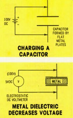
Figure 1. To test the effects of dielectrics on the charged voltage, construct
a capacitor from two flat pieces of metal. Charge it, as shown, remove the
charging battery, and then measure the capacitor voltage using an electrostatic
voltmeter. The meter will show 100 volts, when the dielectric is dry air.
Figure 2. While the 100-volt charge remains in the capacitor of Figure 1, insert a like-sized piece of metal between the plates (being careful not to touch either plate). When the metal is fully inserted, the meter will measure almost zero volts.
Technical models can deceive you. Several months ago, I ran a 10-question quiz about capacitors, and I received many questions and arguments about the answers I gave. I've purposely allowed some time to elapse so all of your ideas could reach me.
Now it's time to explain why the quiz is so difficult for technicians.
And, of even more importance, it's time for the answers.
During a survey--made with the help of NESDA and ISCET--I learned that questions dealing with capacitors were the most difficult for experienced technicians. Later, when I taught an Electronic Industries Association (EIA) course, I brought up the subject for discussion. All of the "students" in the course were experienced teachers.
One of them suggested that students in electronic schools seldom are told actually how a capacitor works. Instead, they are given a "model" that fits most of the situations they will encounter in practical service work.
Here are a few of the characteristics given for the capacitor model:
• A capacitor will pass AC but not DC power. The term "blocking capacitor" is used often to reinforce that thought.
• A capacitor is charged by forcing electrons onto one plate, and taking them away from the other plate.
Commonly, schematics show the charging and discharging paths of a capacitor.
• A larger capacitor holds a greater charge.
• A capacitor is a component that opposes any change of voltage across its terminals.
All of these statements are partially true. However, they can be misleading since they do not cover all situations. They are incomplete.
Now, I want to make clear that I don't oppose the teaching of circuit theory in this way. But, I believe strongly that it's very wrong to give technicians the impression that these are any more than useful examples. They should not be presented as the final and all-inclusive authority on the subject! Several years ago, after I realized that the typical capacitor model doesn't explain some actions, I published four basic applications which are not explained by these convenient models, and challenged technicians to answer the questions.
This aroused a storm of criticism.
My critics said I didn't play fair.
After all, if I chose little-known examples, why should I expect technicians to know the answers? However, that's just the point. They could have answered correctly if their model for capacitors was complete, and didn't need modifications or additions.
One fact emerged from the controversy: most technicians don't understand capacitors.
Other models
Let me digress for a few moments and explain that capacitor theory is not the only subject taught by use of a simplified model.
Probably the most famous model is the one of electron flow for current. It's a convenient way to describe circuit action, but it should not be taken as an absolute and complete truth about electricity. In the future, I'll prove to you that the idea of electron flow is only a model, and it's one which will not work for certain applications!
An important experiment
The capacitor of Figure 1 consists of two flat plates made of metal which are separated by a dielectric of dry air. It is charged from a DC power source, then the charging source is disconnected, leaving the capacitor charged with a full 100 volts that can be measured by an electrostatic volt meter, which does not draw current from the voltage being measured.
In Figure 2, a metal plate has been inserted between the plates of the capacitor, but without allowing it to touch either of the plates.
As the metal is slowly inserted between the plates, the voltage decreases. Also, when the metal plate is withdrawn slowly, the capacitor voltage increases to the original value.
Usually, technicians are confused by the experiment. They have been taught that a capacitor is charged by forcing electrons onto one plate and simultaneously removing electrons from the other plate.
In this experiment, the total number of charges on each plate has not changed. Obviously, the model doesn't explain such behavior.
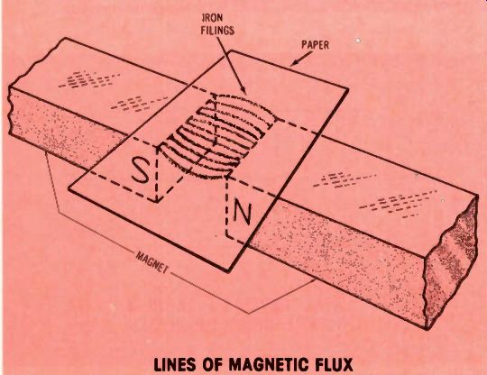
Figure 3. Lines of magnetic flux can be proved by this experiment using
tiny iron filings.
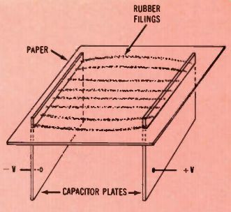
Figure 4. Lines of electrostatic flux can be verified in an experiment similar
to that of Figure 3 by sprinkling tiny rubber filings in the electrostatic
field of a capacitor.
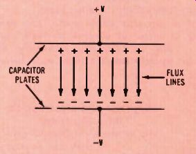
Figure 5. Electrostatic flux lines are thought to extend from the positive
charges across the dielectric to the negative charges of a capacitor. More
lines produce a higher stored voltage after charging.
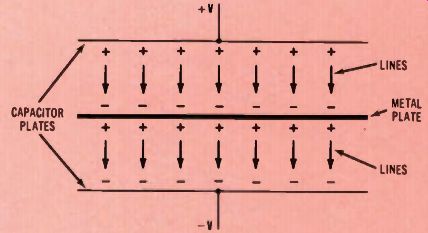
Figure 6. Inserting the metal plate of Figure 2 inside the capacitor prevents
the electrostatic flux lines from extending between the capacitor plates.
Therefore, the stored voltage is almost zero. Other dielectrics reduce the
stored voltage, but not so much.
Magnetic and electrostatic flux ... A review
The previous experiment can be understood only by reviewing the idea of magnetic and electrostatic flux. If a paper is placed over a north and a south magnetic pole, and iron filings are sprinkled on the paper, the small particles of iron will arrange themselves into a pattern of lines, such as those of Figure 3. (Usually the paper must be tapped lightly to allow movement of the particles.) This tests magnetic flux.
A similar experiment can be performed for electrostatic flux by using a capacitor (which has been charged to a very high voltage), and sprinkling finely-ground rubber filings on the paper. When the paper is tapped gently, the rubber particles arrange themselves into lines, as shown in Figure 4. These lines show the presence of high magnetic or electrostatic intensity.
Flux lines in capacitors
As proved by the preceding experiment, when a capacitor is charged, electrostatic flux lines are present in the dielectric between the capacitor plates.
The amount of voltage across a charged capacitor--and the amount of energy stored in a capacitor-depends upon the NUMBER of flux lines in the dielectric! It is convenient to think of each flux line as originating with a positive charge on the positive plate, and ending at a negative charge on the negative plate, as shown in Figure 5. (These positive and negative charges actually are on the inside surfaces of the plates.
They are shown here as though they are not touching the plates. Other drawings show the + and - signs on the outside surfaces, in an attempt to make it less confusing.) When the piece of metal is inserted between plates of a charged capacitor, both positive and negative carriers in the metal move toward the capacitor plates.
Of course, unlike charges attract, and like charges repel. Therefore, the negative charges (from electrons) move toward the positive plate of the charged capacitor, thus leaving the holes (positive charges) near the negative plate of the capacitor.
Figure 6 shows the metal inserted, and the positions of charges on the metal insert. (Although the drawing shows that none of the flux lines extend from one plate to another, in practice the flux lines are not completely eliminated, but are greatly reduced.) The metal insert reduces the total number of flux lines between the capacitor plates. This reduces the capacitor voltage, since the number of flux lines determines the voltage.
If the capacitance was determined by the charges rather than the flux, the metal plate would not affect the capacitance nor the voltage across it.
Effect of a dielectric Imagine now that the capacitor is charged again as shown in Figure 1. But, this time (after the charging source is disconnected), a dielectric material is placed between the plates. Voltage across the capacitor again is reduced, but not as much as when metal was inserted.
From what has been presented already about the effects of flux, it is obvious that the dielectric has reduced the number of flux lines between positive and negative plates of the capacitor. However, the change of flux pattern from the dielectric is not so easy to explain as it was for the metal insert. With the metal insert, the charges were free to move around and align themselves with the flux lines. But, the charges are trapped in the dielectric.
A basic equation
Before I explain what happens inside the dielectric, I should explain how the metal and dielectric inserts have affected the capacitance (Capacitance is a measure of the amount of energy a capacitor can store.) An important equation states: Q = CV, where Q is the charge in coulombs, C is the capacitance in farads, and V is the voltage across this capacitor.
Probably you remember from your school science class that a coulomb is the accumulated charge of 6.25X10^18 number of electrons.
(Note, the number sometimes is incorrectly written as 6.28X10^18 since 6.28 is 2n When metal is inserted between the capacitor plates in Figure 2, the voltage goes down. However, the charge (Q) can't change because there is no path for the current. Therefore, the capacitance must increase to keep the equation in balance. The total result is a decrease of voltage and an increase of capacitance.
When dielectric is inserted be tween the plates, the capacitance increases and the voltage decreases, but not so much as with the metal.
Next Month:
According to the Faraday theory of capacitance, the dielectric has "dipoles" which align when the capacitor becomes charged. This concept will be used to answer the four unusual capacitance questions that don't fit the simplified model.
------
Your comments or questions are welcome. Please give us permission to quote from your letters. Write to Sam at:
J.A. "Sam" Wilson c/o Electronic Servicing
P.O. Box 12901
Overland Park, Kansas, 66212, USA.
-----
(adapted from: Electronic Servicing magazine, Nov. 1978)