By J. A. "Sam" Wilson, CET.
CHANCES IN DIELECTRICS
Your comments or questions are welcome. Please give us permission to quote from your letters. Write to Sam at:
J.A. "Sam" Wilson c/o Electronic Servicing
P.O. Box 12901
Overland Park, Kansas, 66212, USA
Answers about capacitors
In the last Technical Notebook, I described some experiments that demonstrated a very important point about capacitors: The voltage across a charged capacitor and the capacitance of a capacitor depend on the flux lines that start at the positive plate and end at the negative plate.
I know there are some theory people who will argue that the number of flux lines depends on the amount of voltage. But, I've said here that the amount of voltage depends on the number of flux lines.
The reason is that the flux lines are established in the dielectric when the capacitor first is charged. However, when the charging voltage is removed, the voltage that re mains across the capacitor is deter mined by the number of flux lines.
When I mentioned the relation-ship between voltage and flux lines, I was referring to the amount of the flux (and voltage) in a charged capacitor.
Weber-Ewing theory
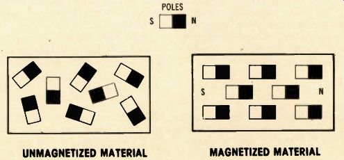
Before I explain what happens in a dielectric when a capacitor is charged, I want to review an old theory of magnetism. The Weber Ewing theory assumes that a magnetic material is made of tiny magnets, as shown in Figure 1.
In the nonmagnetized state these tiny magnets are pointing in all directions at random, so there is no resultant (additive) magnetic field in the material.
Figure 2 shows what happens when all of the tiny magnets are aligned by a strong magnetizing force. The north poles are all pointing in the same direction.
They produce a total magnetic field. Likewise, the south poles are aligned, and they produce a total magnetic field. The overall result is that the piece of material behaves as a large magnet having a single north and south pole combination.
Surprisingly, the Weber-Ewing theory is so close to what actually happens in a magnetic material, that it can be used as an accurate model.
In a previous article, I discussed the domains in a magnetic material.
You should recognize the tiny magnets of the Weber-Ewing model as examples of domains.

Figure 1--According to the Weber-Ewing theory, magnetic material is made
of a huge number of tiny magnets. The poles of these tiny magnets point in
random directions when the material is not magnetized.
Figure 2--When magnetic material becomes magnetized, the tiny mag nets are shifted so the like poles point in the same direction. This gives the effect of one large magnet.

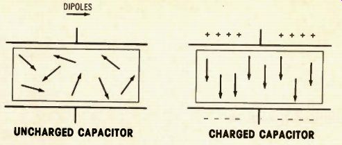
Figure 3--According to Faraday's theory, dielectric material contains a large
number of electric dipoles, which point in random directions before the capacitor
is charged.
Figure 4--After the capacitor is charged, the dipoles all point in the same direction. Therefore, during charge, the dielectric undergoes a physical change.

Figure 5 (A) Without voltage across a capacitor, the electrons in the dielectric
move in circular orbits. (B) Voltage across the capacitor pulls the electrons
into elliptical orbits. This is called "electronic polarization of the
dielectric."

Figure 6 Capacitor voltage changes the equilibrium of the atoms, and it
is called "atomic polarization of the dielectric."
Faraday's dipoles
As an explanation of what hap pens in the dielectric of a capacitor when it is charged, Michael Faraday proposed a model which is very similar to the Weber-Ewing model.
And this Faraday model also is s near to the actual truth that it serves as an excellent model for understanding capacitors.
First, I'll use the Faraday model, then later I'll explain what the di electric dipoles really are.
Assume that the dielectric i made up of a large number of electric dipoles. Each dipole has one positive and one negative charge (see Figure 3). When the capacitor is in an uncharged condition, these dipoles are pointed in random directions.
After the capacitor is charged, the dipoles all point in the same direction (Figure 4). Remember this very important point:
When the capacitor is charged, the dielectric goes through a physical change! In some dielectric materials, the dipoles will remain aligned after the charging voltage is removed. Thus, the capacitor remains charged--with the voltage across it-after the charging step is over. This is the meaning, when we say a capacitor has become "charged." When the capacitor is discharged, the dipoles again become oriented in random directions. As I stated before, this model for charged and discharged capacitors is quite ac curate, and probably I'll refer to it again later.
True nature of dielectric dipoles When a dielectric material is placed in an electric field, there are four factors to be considered: (1) Voltage across a capacitor pulls the dielectric electrons out of their normal circular pattern, and into an elliptical orbit, as shown in Figure 5. This is called "electronic polarization of the dielectric." (2) When two atoms from two different elements combine to make a covalent bond, they do not share electrons equally. More electrons are captured by one of the atoms.
Therefore, the two atoms acquire opposite charges. An external field--such as provided by a voltage at the plates of a capacitor-will change the equilibrium of the atoms (Figure 6). This is called "atomic polarization of the dielectric."
(3) Some materials have a natural "dipole moment." This is the dual (equivalent) of residual magnetism in a soft iron material. Theoretically, a piece of soft iron that becomes magnetized by current through a coil should lose all the magnetism when the current is eliminated. But a small amount of magnetism--called residual magnetism--still remains. The same thing happens in a dielectric, except the field that remains after the charging voltage is removed from the capacitor is electric rather than magnetic.
(4) Any dielectric material always has some charge carriers that are not attached to atoms. When the capacitor has a voltage across it, these carriers--both holes and electrons -gather at opposite sides of the material. Flux lines from the plates terminate at these charge carriers, thus reducing the total flux between the plates.
Now, what does this mean? It verifies the concept of dielectrics made up of many little dipoles (just like the ones Faraday guessed were there). Charging the capacitor forces the dipoles to align with the flux lines between the plates. And that brings us back to the illustrations in Figure 3 and Figure 4.
This discussion explains why there are dipoles in dielectrics. It now should be easier to go back to the more simple ideas of Faraday's model (which is very accurate).
Three quiz questions
It is possible now to use the theory of dielectrics and capacitors to explain several capacitor questions that don't fit the incomplete "tech school" model.
Figures 7, 8 and 9 give the schematics, conditions and a choice of answers. Mark your choice beside the columns and don't read the answers until afterward.

---Figure 7
Question 1. Three pails are constructed so they fit snugly together, as shown. The center pail is made of dielectric material, while the two others are made of metal. After assembly, the capacitor is charged with about 500,000 Vdc. Then, by use of the insulated hook, the pails are disassembled and the two metal pails are touched together. After reassembly, which statement is true? (A) The capacitor has no voltage, for it is discharged. (B) The capacitor still has the same voltage.

---Figure 8
Question 2. A capacitor made of two flat plates (whose distance can be varied) is charged with high voltage when the plates are close together.
After the plates are moved farther apart, which statement is true?
(A) The capacitor voltage decreased.
(B) The capacitor voltage increased.
(C) The capacitor voltage did not change.

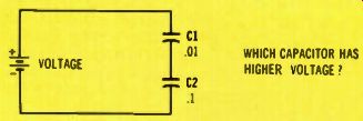
Figure 9
Question 3. Which of the two capacitors has the higher dc voltage across it? (neglect stray capacitances)
(A) Capacitor C1 has the higher voltage.
(B) Capacitor C2 has the higher voltage.
Explanations of quiz answers
Question 1.
When the assembled capacitor of Figure 7/Question 1 is charged, the dipoles in the dielectric become aligned, as shown in Figure 4.
Those dipoles remain aligned as the capacitor is taken apart. Charges in the X and Y metal plates repel each other, and disperse throughout the metal. Therefore, there is no spark or current between the "plates." In fact, nothing happens when the two metal pails are touched together. (If the basic action of a capacitor were, as popularly believed from the student's incomplete model, an excess of electrons on one plate, and a deficiency of electrons on the other, then removal of the solid dielectric would have increased the voltage, and the short would have brought a giant and spectacular arc. Thus the incomplete model is disproved.) If you touch the dielectric pail after it is removed from the charged capacitor, you can feel the static charges. For example, you can bring the back of your hand near the dielectric and see the hairs stand straight out towards the material.
Then when the capacitor is reassembled, the charge carriers in the metal pails regroup because of the flux lines now between the plates. Therefore, the reassembled capacitor exhibits a full charge, and it can be discharged.
Question 2.
In Figure 8, when the capacitor is charged, and then the plates are moved apart, you actually are doing work on the system. Work is defined as force times distance.
Keep in mind the fact that the plates have opposite charges, so you must exert a force to get the plates apart.
Voltage is a measure of the amount of work done in moving a unit negative charge from a positive point to a negative point. Since the distance between the plates is greater, the work required to move the negative charge away from the positive plate and toward the negative plate will be greater. In other words, the voltage has been increased. However, the increased voltage was not obtained for nothing. Work was performed.
Actually, the principle of Figure 8 is the basis for understanding parametric amplifiers.
Question 3.
The answer to Question 3 in Figure 9 is found in the equation:
Q = C x V, where Q is the charge, C is the capacitance, and V is the voltage across the capacitance.
Therefore, the charge for C1 is: Q1 = C1 x V1, and the C2 charge is: Q2 = C2 x V2.
But, the capacitors are in series, so the same amount of charge must be in each capacitor. In other words, the same number of electrons have to move into each negative plate.
Because Q1 equals Q2, then it follows that C1 x V1 = C2 x V2.
After dividing each side of the equation by V1 x C2, you have C1/C2 = V2/V1. This is a simple mathematical way of saying: Voltages across the capacitors are inversely proportional to the capacitance values. In other words, the larger voltage always must be across the smaller capacitor.
Next month---One more question of the four remains to be discussed next month. In the meantime, try to modify your capacitor "model" to include these ideas.
-----
(adapted from: Electronic Servicing magazine, Dec. 1978)