By J. A. "Sam" Wilson, CET.
Your comments or questions are welcome. Please give us permission to quote from your letters. Write to Sam at:
J.A. "Sam" Wilson c/o Electronic Servicing P.O. Box 12901 Overland Park, Kansas 66212, USA.
The old watered-lightbulb trick Lecturers can be classified into two broad categories: stand-up lecturers who are very formal, use lecture notes and tolerate no nonsense; and conversational lecturers who talk about the subject in a conversation al style and rarely (if ever) use notes.
If you have attended my work shops or seminars you'll recognize that I'm in the second category. My style has been described as casual, loose, and (sometimes) sloppy.
But, it wasn't always that way.
About 20 years ago, I took a teaching job in a small California college. Although I had been teaching for several years, the new job and the type of school combined to give me the idea I should operate as a stand-up lecturer.
I made course outlines, gave quizzes every Friday, and lectured in a monotone for full-hour periods.
In my mind, I thought I was doing fine.
The students, of course, regarded the whole thing as a crashing bore.
They began to look for any kind of relief from what seemed to them an endless chain of dull facts.
At first they tried the usual pranks, such as drawing caricatures of the teacher on the blackboard, setting the room thermostat to 90° and placing a mouse in my desk drawer. But, I gave no hint that I noticed.
On and on I droned, day after day. Nothing but facts, facts, facts.
Then one day I entered the classroom, walked up to the chalk board and turned on a small 60-watt bulb that hung over the board.
I stopped cold. In the bottom of the lightbulb was about 1/4-inch of water. And the bulb was glowing normally! While I was standing there, just staring in disbelief, a front -row student said, "Hey, look! There's water in the lightbulb." That remark triggered comments and questions from all around the room.
"How did water get into the lightbulb, Mr. Wilson?" Not only did I fail to give an answer, but I couldn't even speak.
After about two minutes the bulb flickered and burned out. I un screwed it from the socket and examined it carefully. There was not a clue. I left the room and showed the bulb to several other instructors. Each looked appropriately amazed, but none could explain it.
Needless to say, there was no stand-up lecture that day.
Later, one of the students came to my table in the cafeteria and explained. "It was a joke, you know. We ruined about 20 bulbs before we got one to work. We held the bulb under water and worked a needle between the glass and the metal base. After water seeped into the bulb, we sealed it with wax, and then glued over the wax." Epilog Last week, one of my students at Colorado State University stopped at my desk after class. "I was home over the weekend, and my dad showed me something that's really weird." "What was that?" I asked.
"It was a lightbulb with water in it. He says it probably came in through the wires. He's pretty smart about electronics. He studied at a small college in Los Angeles.
I'd like to have you meet him sometime."
"Well," I said, "it wouldn't surprise me to find that I have met him already."
An 18-cent voltage regulator
An old slogan stated that "What this country needs is a good 10-cent cigar." After all the talk about smoking and cancer, that saying isn't heard often anymore. Anyway, inflation would change it to "a good $1.00 cigar." So, I have a substitute. What this country needs is a good 18 -cent voltage regulator.
I have a solution for that need.
Textbooks often list two purposes for the bleeder resistor in a power supply. One obvious purpose is to discharge the filter capacitors after the supply is shut off.
Secondly, a bleeder resistor improves the voltage regulation of a supply. This is not needed for supplies that have amplified closed-loop regulation. It's very useful for unregulated supplies where the current drain varies widely.

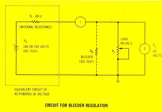
Figure 1--Use this circuit to check the effects of bleeders on power -supply
regulation. The internal resistance is the sum of all resistances in the
voltage source. For the third calculation of regulation, the source voltage
is changed to 150V. Thus the average output voltage is approximately the
same as for the previous tests with 100V.
How much regulation?
Using the basic circuit of Figure 1, the voltage regulation will be calculated for no bleeder and two values of bleeder resistance as the load resistance is varied between 40 (-) and 140 (") .
Regulation of a power supply is judged by how much the output voltage changes for different values of load current or resistance. It can be expressed either as a percentage or by the voltage change.
For purposes of calculation, the dc voltage source is considered to be a perfectly -regulated voltage in series with the internal resistance of the supply. In a typical brute -force power supply, the internal resistance is the sum of the rectifier's forward resistance, the value of any surge -limiting resistors, wiring resistances, and the de resistance of the transformer winding.
Formula
If you like your technical discussions laced with a little math, then you can follow the calculations.
Otherwise, just skim over the figures and examine the results of each example.
Here is the basic formula for proportional voltages:
(Equation 1) VL = vs RL Ri-f-RL where: Vs is the supply voltage VL is the load voltage RL is the load resistance R1 is the internal resistance
Without a bleeder
After substituting 100 for the supply voltage and 40 S2 for the internal resistance, the equation be comes:
VL = 100( RL 40+RL
This is the equation when the load resistance is 40 ohm :
VL = 100 ( 40 40 40 VL = 50V
And when the load resistance is changed to 140 ohm , the equation becomes:
00( 140 VL = 1 40+140 VL = 77.7 V
In other words, the output voltage increased by 27.7 V when the load was changed from 40 ohm to 140 ohm . This is poor regulation, probably because of the high internal resistance.

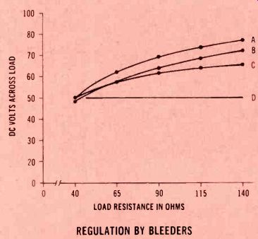
Figure 2--These are curves of the regulation calculations.
Curve
A shows the curves obtained from five different load resistances without a bleeder. Curve B is the same except a fixed 400-ohm bleeder is connected in parallel with the variable load. For curve C, the supply voltage is increased to 150 V and a 40-ohm bleeder is added. Perfect regulation is represented by the straight line of Curve D.
400-ohm bleeder
A general method for finding the value of a bleeder resistor is to select one that draws 10% of the amount of load current. In this case, the value is 400 ohm when the load is 40 ohm . (Of course, the bleeder current is more than 10% when the load is adjusted to 140 0 .) The load on the supply (RO) is the value of RL and RB in parallel.
thus R0 = RgxRL RB+RL
When the values are substituted, the equation becomes:
400x40
Ro =
400+40
RO = 36.36Q 400x140 Ro 400+140 Ro = 103.70
Substitute in Equation these two obtained:
VL = these two resistances 1 (given before), and output voltages are 36.36 40+36.36
VL = 49.56 V
VL = 100( 103.7 40+103.7 VL 72.2 V
Without a bleeder, the voltage changed 27.7 V, and with a 10% bleeder, the change is 22.66 V.
Therefore, an 18-cent bleeder resistor does improve the regulation.
This improvement, however, is disappointing. Perhaps an increased bleeder current will help.
40- ohm bleeder
A 40-ohm bleeder resistor paralleled with a 40-ohm load resistance presents a 20-ohm load at the output. (No formula is needed for that one.)
When the 40-o bleeder is added to the 140-o load, the parallel resistance formula is worked this way:
40x140
RO
=
40+140 Ro = 31.10
Such low values will reduce the output voltage below the previous average level. To compensate, the supply voltage is changed to 150 V.
The output voltage under both loads are calculated this way:
VL = 150 ( 402+020 )
VL = 50 V
VL = 150( 31.1 ) 40+31.1
VL = 65.6 V
The variation of output voltage now is only 15.6 V, which is improved regulation. However, the efficiency is worse. Whenever the load resistance is higher than 40 ohm , more current flows in the bleeder than in the load.
Summary
Power-supply regulation is improved by adding a stable bleeder current. And higher bleeder current improves the regulation, but at the expense of inefficiency.
Figure 2 shows a graph of the three ranges of output voltage versus the various load resistances.
The bottom line represents perfect regulation.
In actual equipment, few "brute-force" power supplies have such a high internal resistance, but the regulation principle is the same.
With power supplies that use a bleeder, the output voltage will increase if it opens. This must be considered when you troubleshoot.
Delayed mail
Because I made many trips this year, my mail has not all reached me. I'll reply as soon as possible.
Here are a couple of questions that some of you might be able to answer. If so, write to me in care of Electronic Servicing.
Ignition scop
F. J. Pisano of Girard, Ohio wants to know how to convert his scope for use in analyzing auto ignition systems. The commercial scopes all have some kind of triggered sweep, but I have no information about converting a service scope. My impression is that such a conversion would require an excessive amount of trouble and expense.
If you can advise this reader, please write to me.
Upgrading
Glen Trotten of Sacramento, CA asked if my monographs would help him obtain a WG10 grade.
The answer is "No." Monographs are specialized publications about just one subject.
They are useful for increasing your knowledge and skill in one segment of the electronics field.
For upgrading tests, it's usually better to study a broad range of subjects. Books are the best source of general knowledge, and I recommend that you check the Howard W. Sams Book Catalog.
Also see: Sam Wilson's Technical Notebook: COUNTER GLITCHES