
By Carl Babcoke editor, and the Electronic Servicing staff
Advances in oscilloscope technology made it possible to view waveforms that could hot have been locked or displayed a few years ago. Improvements in stability bandwidth, faster sweeps, expanded waveforms and other new features have made older scopes obsolete at a time when present-day state-of-the-art technology demands the best performance. These explanations and the technical specification charts should help you it selecting the brand and model of scope that is best for your needs.
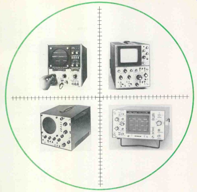
Many important improvements have been made in scopes over the years and older features or specifications have been eliminated. Those previous factors are not mentioned now, except perhaps to illustrate the superiority of new scopes compared to the many obsolete ones that continue to be used (or ignored) in electronic shops.
Tubes versus solid state--The battle between tubes and transistors is over. Tubes lost. No tubes (except CRTs, of course) are used in any newly introduced models.
Scopes with solid-state components share in the general advantages of other solid-state equipment (less internal heat, smaller physical size, lower power consumption and longer life with less maintenance).
More importantly, they benefit from increased stability.
This stability is valuable because of former problems that are eliminated. The drift of vertical-amplifier gain now is very small, which allows the calibration control to be removed from the front panel. It's no longer necessary to calibrate the scope each time peak-to-peak volts are to be measured accurately.
Also, the positioning or centering of the waveform is much more stable.
Many of the new scopes will run for hours without falling out of lock.
(Part of this improvement is from triggered sweep; but some is possible because of the solid-state de vices.) Recurrent versus triggered sweep Latest test-equipment catalogs from scope manufacturers list almost no recurrent-sweep models. Of the five models offered by one well-known manufacturer, only one has recurrent sweep.
This overwhelming acceptance of triggered scopes proves they are easily worth the slightly higher price tag.
Perhaps the most unique difference between recurrent and triggered scopes is that recurrent scopes lock according to the frequency of the signal. However, a triggered scope sweeps for a definite period of time (after it's triggered) and shows whatever segment of a waveform is there during that time. A half-cycle or 9-1/3 cycles might be displayed, depending on the signal frequency. It's all the same to the scope.
Sweeping for a certain time rather than with a definite frequency allows triggered scopes to lock securely onto waveforms that can't be locked at all by recurrent types.
Pulse trains and some video wave forms are examples. Recurrent scopes also can't show one-shot events, such as transients or a single damped-wavetrain.
Additional information and illustrations are given in the Tips For Using Scopes article, found else where in this issue.
Measures ac and dc--One big advantage of modern scopes is the option of reading ac or dc voltages (or both combined). This is made possible by dc-coupled vertical amplifiers having flat response from de to the rated top frequency. Both ac and de have the same calibration. A deflection of one centimeter (or one division) indicates the same dc voltage as it does peak or peak-to-peak ac voltages.
When an ac waveform without any do is required, a front panel switch connects a coupling capacitor.
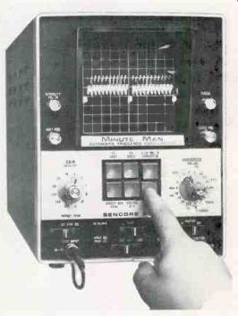
Six pushbuttons on the Sencore PS-29 "Minute Man" panel select
the sweep times most often needed. Also included is the usual time/cm switch
with frequency markings. Locking is automatic without any variable controls.
All of the new scopes surveyed have a switch for ac or do operation. Again, there is no controversy, except to those who have never made any do measurements with a scope. It is helpful to learn to make do and combined ac/dc voltage measurements.
-------Dual-trace and dual-beam features allow two separate waveforms to
be displayed at the same sweep speed.
This is very useful for comparing the phase of signals and for fast trouble shooting of intermittents.
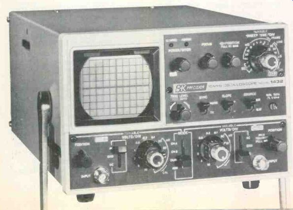
---------Model 1432 from B&K-Precision is a 15-MHz dual-trace portable
scope that operates either from line voltage or 12 Vdc. It has a 3-inch
CRT and a vertical sensitivity of 2 V/div.
Multiple traces--Two methods permit more than one trace to be viewed on the screen simultaneously. One way is to use a special dual-beam CRT which has two separate sets of vertical deflection plates and two electron streams.
There are three advantages. It is impossible for the two waveforms to be out of phase, for only one sweep system and locking circuit are operating. Both traces are brighter than those of dual-trace, since both are present at all times without any time-sharing. The waveforms show no chopper interference at any sweep time and they have less flicker at slow speeds than does alternate sweep. One disadvantage is the higher cost compared to a dual-trace scope of equal specs.
Dual-trace is a time-sharing arrangement of alternating the two waveforms which then are applied to a conventional single-gun CRT.
However, two kinds of time-sharing are offered. For high-speed short-time sweeps, the two wave forms are viewed consecutively.
That is, one complete trace shows the waveform of channel 1, while the next complete horizontal trace has the waveform of channel 2.
Each trace is slightly less bright than one alone would be, because each one is seen only half of the time. This is called alternate sweep, which is not desired for low repetition signals because of the doubled flicker. At very low speed times, only one trace can be seen at a time, and that's very distracting.
Alternate trace is recommended for fast sweeps only.

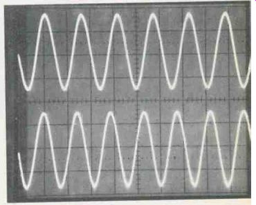
--- A 5X magnifier (expander) increases the horizontal sweep to 5 times
screen width. Top trace is the sinewave signal needing magnification,
while the bottom trace shows the same signal after the 5X switch is turned
on. No other adjustments were made.
This gives the effect of dividing the sweep time by 1/5 which spreads the waveform by a factor of 5.

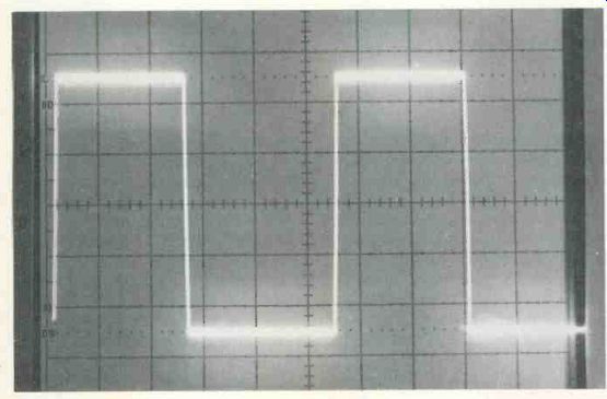
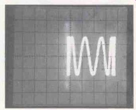
------- This waveform illustrates two things. First, the model 935A
Tektronix scope has a signal delay line so the leading edge of pulses
can be seen. And the square wave shows proper compensation of the 10X
low-capacitance probe when adjusted to the scope's calibration waveform.
Chopped sweep also alternates, between the two waveforms, but it does so by means of a chopper that operates between 100 kHz and 500 kHz. Each waveform is sampled alternately for a very short period of time, so the many small pieces of waveform blend together and appear to be continuous. However, if the waveform frequency is a sub-multiple of the chopper frequency, parts of the waveform will be missing. That's why the chopped mode should be used only for low-frequency signals, and never for higher sweep frequencies. Some scope models switch automatically from one mode to the other at a certain sweep time. Others allow the operator to make the decision.
Waveform-storage scopes--Storing waveforms on the screen of special CRTs can be done in three general ways: bistable; variable persistence; and fast mesh-transfer. Each of the three is superior for certain kinds of waveforms. Bistable can store waveforms for an hour or more and is particularly effective in showing fast leading and trailing edges.
Storage by variable persistence is limited to about 30 s, but it greatly increases the brightness and contrast of dim low-rep-rate pulses, and efficiently stores single-shot events. For very-high writing speeds with either bistable or variable persistence modes, the fast mesh transfer system is essential.
Digital storage--A conventional CRT can be used in scopes that store waveforms digitally. The analog voltage waveform is converted to digital signals that can be stored indefinitely. Frozen waveforms and wave trains that move as though they are being deflected are two features of digital scopes. There is no flicker at slow sweep speeds.
Perhaps the most serious limitation (other than cost) is in band width. First applications were in medical equipment, where the waveforms are swept at slow speeds, and bandwidth can be narrow.
There are a few exceptions. The Gould model OS-4000 apparently can be operated as a conventional 10-MHz scope or with digital storage and refresh at slow sweep speeds. Digital sampling is done at a 1.8 MHz rate, and the storage uses a 1024 X 8 bit memory.
Digital scopes are priced in the $4000 to $5000 range.
Delayed sweep-Another new feature is a second horizontal sweep.
With the usual waveform on the screen, the operator selects (by a brighter area) the position and width of a window which includes the section of waveform to be expanded. When the delayed sweep is switched on, the screen shows only the part that was in the window, but it's expanded to cover the entire field.
Sometimes a similar effect can be obtained by using the usual sweep expander. But delayed sweep gives a more stable trace with less jitter, and it offers other advantages with certain waveforms.
Sweep expansion-Almost all triggered scopes have some means of increasing the width of the horizontal trace. Some have a switch that expands the sweep by a factor of 5.
This is called "5X magnification." Although the width is increased electronically by fives times, 4/5 of it can't be seen. The part that can be seen is expanded as though a 5-times shorter sweep time is used.
Any section of the expanded wave form can be viewed by adjustment of the horizontal-positioning control. Since the beam is seen for only 1/5 of the time, the trace is less bright.
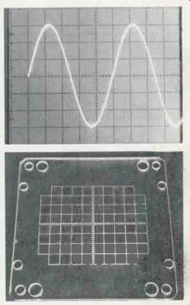
------- Three types of graticules are used for CRT calibrations. (A)
Tektronix and perhaps several others have black calibrations on the inside
of the CRT.
This totally eliminates parallax (error from reading at an angle). Some others have black lines on plastic external to the CRT. Both of these require external illumination (as shown) to make the lines readily visible. Many other scopes (B) have grooved lines in clear plastic. These are illuminated by edge-mounted bulbs. If you want accurate readings with external graticules, look straight into the center of the CRT screen.

---------Model
MS-215 "Miniscope" from Non-Linear Systems operates
for three hours on internal sealed lead-acid batteries requiring a charge.
This dual-trace model has 10 mV vertical sensitivity and sweep times from
0.5 s/div to 0.1 us/div.
Delay line--When a conventional scope is called on to trigger (begin the horizontal sweep) at the leading or falling edge of a pulse or square wave, the edge has occurred, already before the trace can begin to move. Therefore, this trailing or leading edge is missing from the waveform.
It's not possible to trigger the sweep before the triggering point arrives, so the opposite action must be taken. The vertical signal is delayed in time.
A sample of vertical waveform for the triggering circuit is taken from the vertical signal before it is sent through the delay line. And the time-delayed signal at the output of the delay line is amplified before it is used to deflect the CRT. Therefore, the leading or trailing edges of square waves or pulses can be seen.
Calibration waveform--Most triggered scopes have a square wave signal that's available somewhere on the front panel. Usually, the amplitude has been factory adjusted to serve as a test of the vertical gain. But that's not the most important function. The waveform is used to adjust the X10 low-capacitance probes.
Normal X1 probes need no adjustment. Their response always is flat, although the added capacitance of the cable often detunes or smears the waveforms of critical circuits.
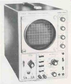
--------- Vertical sensitivity of 10 mV/cm and triggered sweep from
0.5 s/cm to 0.5 us/cm are some specifications of the workhorse Simpson
model 455T single-sweep scope.

--------- A very unusual instrument is the Vu-Data PS-935/975 which
combines a 35-MHz dual-trace scope with a digital multimeter and a frequency
counter. Each can be used independently or all together.
The units operate on line power, external 12 Vdc or from an optional pack fastened to the bottom.
Low-capacitance X10 probes, however, operate by the double voltage-divider principle. A 9-M n resistor is placed inside the probe tip, and this in conjunction with the 1-Mo scope input resistance gives a do reduction of 10 times (output is 1/10 of the input). Without a variable capacitor across the probe resistor, the circuit becomes a low-pass (or high-frequency attenuation) filter which rolls off the higher frequencies at an alarming rate. With the capacitor, the circuit becomes two attenuators. One is made up of the probe capacitance versus the total capacitances of probe cable and internal scope wiring. This voltage divider must give the same attenuation as the resistive one (already described), else the frequency response will not be flat.
When the probe is compensated (that is, both voltage dividers are matched), the frequency response is flat from dc to the scope's top frequency.
--------- A few brands of scopes (such as Tektronix) have a beam-finder
that returns the trace to the center of the CRT regardless of wrong centering
or excessively tall traces.

---------- Ballantine model 1032A is a full-featured scope with a very
unusual second triggering system that permits viewing two separate waveforms
of different frequencies. Each dual-trace channel has its own independent
trigger circuit. Other features include 20-MHz response and an X10 magnifier.
Flat response is required to properly reproduce fast rise-time waveforms, of course. Equally important is that only flat response can provide the same amplitude measurement accuracy for sine waves of all frequencies.
Extended high-frequency response--Unexpected problems are faced by scope manufacturers who attempt to widen the bandwidth beyond a certain point.
One problem involves the design of amplifiers that can give flat response from do to several hundred thousand MHz. That's very difficult; however, a more serious limitation is in the scope CRT itself.
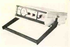
-------Model CAG-22 from UFI is a digital-storage device that can be connected
to a triggered scope to obtain the benefits of low-frequency digital storage
and display. Provides flicker-free waveform display and bright storage of
transients or one-time events.

---------In the "Gee Whiz" category is the Tektronix model 7104,
which is the only real-time model that can display a 1-GHz signal. This
is pushing scope state-of-the-art to the outer limits. If you need one,
it's a bargain at $19,485 with typical plug-in units.
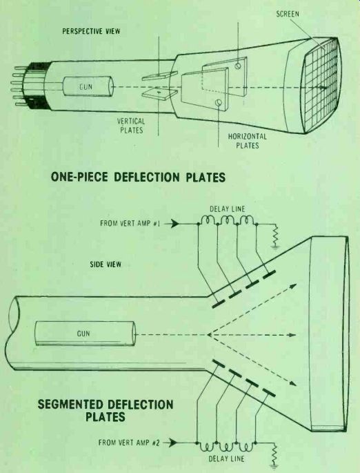
------- Scope CRTs have a reduction of deflection above certain high-frequency
limits. It's caused by a phase change during the time the beam passes
the large plate. One solution is to use several vertical plates and apply
a successively delayed signal to each small plate in turn.
Look at it this way: a significant length of plate is necessary to provide sufficient electrostatic deflection. Unfortunately, at those extremely high frequencies, the signal phase might change during the time required for beam movement along the deflection plate's total length. In an extreme example, a 180 dergee phase delay would cancel nearly all of the deflection.
Less phase changes still reduce the deflection, which is equivalent to a loss of high-frequency response.
One solution is shown in the drawing of conventional and wideband CRTs. Each vertical deflection plate is broken up into several.
Then the individual plates are supplied with signals that have been delayed in time by a tapped delay line or transmission line.
When the factors are matched correctly, the beam is affected by the same relative phase of signal.
Thus, a combination of flat amplifier response and equal deflection for all frequencies provides the same amplitude for each frequency within the scope's bandwidth rating.
The undisputed champion of wide-band scopes is the Tektronix model 7104 which is rated at 1 GHz-and that is equal to 1000 MHz! That's a hundred times more bandwidth than a 10-MHz electronic service scope. Before the 7104, the only scopes that could display 1 GHz waveforms did so by sampling; there were no real-time scopes for those stratospheric frequencies.
Comments
These facts about features of some new scopes were provided to help in deciding what kind of scope is needed now and in the future.
For audio, stereo multiplex, AM radio and TV servicing, a scope having a bandwidth to only 10 to 15 MHz is sufficient. However, for the new tuner-control and remote-control circuits using digital logic, a wider bandwidth is preferable. Of course, it is possible to examine a pulse waveform that has rounded corners and imagine what it would look like if displayed on a wider-bandwidth scope. But remember that the sweep times are matched approximately to the usable frequencies of each scope. In other words, a scope that's not intended for pulses or digital work probably will not have the short sweep times necessary to display those narrow pulses or the pulses that have large blank spaces in between.
For CB-radio diagnosis and digital analysis, the scope should have a maximum top frequency of at least 25 MHz. Of course, a 30 MHz to 35 MHz model is even more suitable.
Look to the future--Don't base the selection of a new scope on the features and bandwidths needed today and a year in the future. Instead, consider the trends in technology, make a good educated guess about the specs needed for at least five years, and only then decide which model and brand to buy.
These comparative charts of most scope models can help in selecting the one scope that best meets those present and future needs. Choose wisely, because scopes are becoming more indispensable every year.
Also see: Better waveforms with wideband scopes