By Carl Babcoke
Each report about an item of electronic test equipment is based on examination and operation of the device in the ELECTRONIC SERVICING laboratory. Personal observations about the performance, and details of new and useful features are spotlighted along with tips about using the equipment for best results.

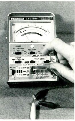
Figure 1--LEDs on the panel of Leader model LTC-906 transistor checker
show good or bad transistors in-circuit. Additional parameters are read
on the meter during out-of-circuit tests. No variable controls are used;
all test set-ups are made by switches for fast operation.

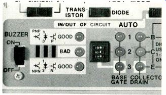
Figure 2---Socket and controls for in-circuit transistor tests are located
on the lower-left section of the panel.
Transistor tester
Leader Instruments model LTC-906 (Figure 1) tests transistors, diodes, FETs, BJTs and SCRs either in-circuit or out-of-circuit.
The in-circuit good/bad and base identification tests can be made rapidly since the readout is by LEDs. Out-of-circuit tests measure transistor beta, B/E dc voltage (identifies material) and collector-to-emitter leakage. Results of these tests are displayed on the mirrored-scale meter.
In-circuit tests
During an in-circuit good/bad test of transistors, the internal circuitry evidently tries every combination of the three leads. There fore, it is not necessary to connect the three test leads to any certain elements of the transistor. If the transistor is a PNP type that has some gain in the circuit, an LED marked "PNP" and "good" flashes on and off continuously. In addition, two or three LEDs at the right of the transistor socket (Figure 2) flash on and off in time with the "good" LED. These LEDs are part of the six that identify the base and the two transistor leads that connect to collector or emitter. If only two of the six LEDs flash, the one in the left vertical row indicates the lead that connects to the base. And the one in the right column identifies the collector. By elimination, the one remaining is the emitter.
However, many transistors light three LEDs. In such cases, an out-of-circuit test is required to determine which is collector and which is the emitter. However, for most in-circuit tests, it is not necessary to know collector from emitter. It is enough to know the transistor is not open and that it does give gain.
The "high" and "low" drive switch has two uses. Some low-impedance circuits require the high setting before a "good" indication can be obtained. When two LEDs light in the collector column, reducing the setting to the low-drive position might allow only one LED to light. Thus, the collector is positively identified.
If the base is open to either collector or emitter (or the transistor has no gain for any reason), the "bad" LED at the left of the socket lights steadily.
For NPN transistors, the tests are the same except a good one causes the "NPN" "good" LED to flash.
In-circuit tests because of their nature cannot be precise or totally reliable. Low resistances or high capacitances of the circuit can nullify any in-circuit test. Even so, such tests can be extremely valuable. Most circuits permit the transistor to have some gain during the test, and this usually is sufficient for a satisfactory preliminary evaluation.
If the "bad" LED lights, the schematic should be examined.
Where no low resistances or reactances are found in the stage, it's certain the transistor actually is defective. Of course, such transistors should be removed for a second test.
Buzzer--Located just to the left of the "bad" LED is a buzzer which sounds during each flash of either "good" LED. This allows the operator to watch the circuit connections instead of the tester while hearing the decision of the checker.
A "buzzer" switch is provided to turn off the buzzer when not wanted.

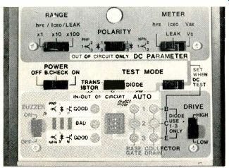
Figure 3---Switches on the upper and right sections of the panel are
operated during out-of-circuit tests of beta, CIE leakage and B/E voltage
drop.

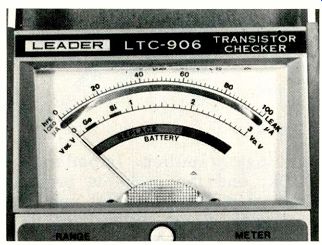
Figure 4--The meter has three scales. At the bottom is the "replace/good" battery
test. Base-to-emitter voltage (with green areas showing the tolerance
of silicon and germanium types) is displayed on the center scale. Beta
and collector-to-emitter leakage are shown by calibrations of the scale
at the top of the meter face.
Tests--In summary, the in-circuit tests identify PNP versus NPN types and indicate if the transistor is good or bad. In most cases, all three leads are identified, regardless of how the tester is connected to them.
Out-of-circuit checks
Each transistor must be plugged in or connected correctly during all out-of-circuit tests. Usually base, emitter and collector will be known from the in-circuit tests. Any question about a reversal of collector and emitter can be resolved with the "polarity" switch later.
Seven switches control the out-of-circuit dc parameter tests (Figure 3). Of course, the "power" switch is used also for in-circuit tests. It has a position for reading the internal 9-V battery condition.
One switch selects tests for a transistor or a diode. The other test mode switch allows either in-circuit dynamic checks or out-of-circuit dc tests.
Bias--Voltage drop across the base/emitter junction is measured on the mirrored-scale meter (Figure 4). Calibrations are in volts, with a maximum of 3 V. Green sections centered around 0.3 V for germanium and 0.7 V for silicon show the material of the transistor that's under test.
If the B/E junction is open or the leads are reversed, the meter reads slightly more than full scale.
I_ceo leakage--Collector-to-emitter leakage from 2 uA to 10 mA are measured in three ranges. (Iceo means: current between collector and emitter with base open.) Tests with known defective transistors indicated these ranges are sufficient.
Hfe---Beta from 2 to 10,000 also can be measured in three decade ranges. Tests with transistors (that previously had been checked by five other testers) showed good accuracy, except for a tendency to show higher readings for transistors of high beta. Of course, no two methods of measuring beta seem to give identical results. It is import ant for a beta tester to provide repeatable readings (which the LTC-906 does) so comparisons can be made.
Polarity---Correct setting of the "polarity" switch is necessary during leakage and beta tests. Usually the leakage will appear to be excessive if the polarity is reversed.
If there is any question about the collector and emitter being reversed, the correct connections and polarity are the ones giving highest beta. (Many transistors have some gain even with the collector and emitter interchanged.) Just slide the polarity switch from PNP to NPN and back again. Leave it at the position that shows the highest beta reading.
Comments
The model LTC-906 transistor checker fulfilled the promises of providing rapid and accurate transistor tests. A test cable consisting of a 3-prong plug with three color-coded wires and clips allows either in-circuit or out-of-circuit transistors to be connected. Transistors with wire leads (either flat or round) can be plugged directly into the socket on the front panel. A plug on the top of the case allows the use of an external voltage supply.
Also see: Reports from the Test Lab