Each report about an item of electronic test equipment is based on examination and operation of the device in the ELECTRONIC SERVICING laboratory. Personal observations about the performance, and details of new and useful features are spotlighted along with tips about using the equipment for best results.
By Carl Babcoke
"Connect a capacitor of unknown value to an instrument, turn on the power, and rotate the selector switch to higher ranges until the overrange indication changes to a direct digital readout of capacitance." Most measurements can be that simple when the instrument is a model 820 Capacitance Meter from B&K-Precision. Stable and highly accurate readings are obtained within a fraction of a second, except for very large capacitance values that require more time.
Features
Model 820 B&K-Precision Capacitance Meter (Figure 1) has a 4-digit LED readout with a decimal that moves according to the setting of the range switch. The 10 range-switch positions allow measurements of capacitances between 0.1 pF and 999,000 uF.
Most of the internal circuitry is digital which matches the digital readout. The stability is so good that a zeroing control is not needed except for the 1000-pF range where it's used only to compensate for the stray capacitance of test leads (when they are connected).
Accuracy is 0.5% +- Least-Significant Digit (LSD) up to 100 uF, and it is 1% above 100 uF. Four "C" cells furnish power for about six hours of continuous operation. Pro visions are made for NiCad cells and an external charger as an extra-cost option. A carrying case is available also. The meter is about 6-1/2"x4-1/2"x2-1/2." All measurements are direct reading in pF, nF, uF and mF. A handy conversion chart is printed on the back of the case. The overrange indication appears as four horizontal dashes at the bottom of the display.
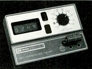
Figure 1 Measuring capacitances with the B&K-Precision model 820
can be this simple. Accuracy of most ranges is 0.5% ±1 digit.
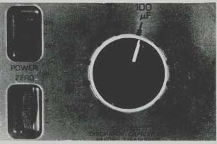
Figure 2 Ten decade ranges measure between 0.1 pF and 999.9 mF.
Maximum reading of all ranges is one less than the markings. For example, the 100 uF range reads from 00.01 uF to 99.99 uF. Over-range occurs above that value. The edgewise-mounted knob for zeroing is at the left below; it is used only for the 1000-pF range.
Tests by charge and discharge
Model 820 measures the amount of time required to charge the tested capacitance to a certain dc voltage when a constant current is applied. This is a time-constant action that permits larger capacitances to charge more slowly than smaller ones do. Linearity is achieved by arranging a different maximum charging time for each range so each test is completed in far less than one time constant.
Ten decade ranges (Figure 2) are required to allow measurements over such a huge span of capacitances. They are handled by a single counting and display system and a proper selection of these four conditions:
one of the five clock frequencies;
one of the three discharge frequencies;
one of the two stop-count charging voltages; and
one of the four constant currents used for capacitor charging.
For example, the smallest-capacitance range (999.9 pF full scale) has a crystal-controlled clock frequency of 4 MHz, a stop-count dc reference of 2.5 V, and a constant current of 1 uA. No measurement in this range requires more than 2.5 mS to complete. The 999.9 mF (.9999 F or 999,900 uF) range has a clock frequency of 400 Hz, a charging voltage of 0.5 Vdc, and a constant current of 20 mA. About 25 s are required for a full-scale reading of this highest range.
Shorted capacitors cause an over-range indication on all 10 ranges, and an open capacitor usually measures only a few picofarads on the most sensitive range. No leak age test is provided.
Operating tips
Operation of model 820 is extremely uncomplicated and requires very little interpretation of the readings. However, these next tips should answer some questions and perhaps save time for the user.
Figure 3 shows proper adjustment of the "zero" control. This control affects only the 1000-pF range, and should not be adjusted when other ranges are in use. The control can compensate for up to 20 pF of stray capacitance when test leads are used with the 1000-pF range.
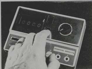
Figure 3---For the zeroing adjustment, select the 1000-pF range and rotate
the zero knob until the readout goes from 000.2 to 000.1 and barely to
000.0.
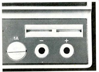
Figure 4---Metal plates behind the slots are paralleled with the two banana
jacks. Capacitors with leads can be plugged into the slots, while electrolytics
and others large capacitors should be connected by test leads to the
banana jacks. Never test a charged capacitor, although the fuse is provided to minimize any damage to the meter.
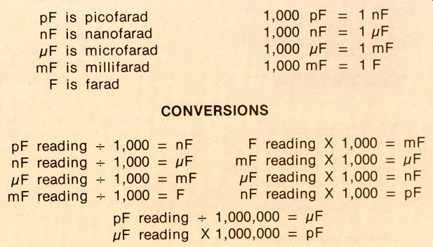
Table 1----Many technicians are not very familiar with the term "nanofarad" (nF)
which is midway between microfarad and picofarad. Use this table to convert
nF to either uF or pF.
Two facts should be kept in mind. First, the control is a multi-turn type requiring several revolutions to produce much change of reading. Second, no negative count (below zero) is possible. With no capacitor connected, therefore, rotate the knob in an upward direction (toward the + sign) until the 1000-pF range shows some reading. Then rotate the knob in the opposite direction until the reading alternates between 000.1 and 000.0. If extreme accuracy is required, this adjustment should be done with the test leads lying in approximately the proper position, but not connected to the capacitor that's to be tested. Of course, if test leads are not needed, they should be removed and the zeroing per formed again before any capacitors are plugged into the slots (see Figure 3).
Polarity of the test leads does not need to be observed with paper, film, ceramic or mica types, but only with electrolytics.
The jacks for the test leads are in parallel with the spring-loaded metal plates in the two slots which are just above the jacks (Figure 4). To the left of the jacks is a holder for a 1-A fuse that protects the meter against chassis voltages or charged capacitors.
Do not connect a charged capacitor to the meter; always discharge each one before a test is made.
Capacitor leakage
Only one condition will produce a noticeable difference in capacitance reading when the range switch is turned from one position to another: leakage across the capacitance.
Capacitors with low leakage show the same capacitance when checked on two or three consecutive ranges, except for the inevitable rounding off of the least-significant digit. For example, a low-leakage 0.1 uF capacitor gave these three readings:
99.42 nF on the 100 nF range;
99.0 nF on the 1000 nF range;
and 0.099 uF on the 10 uF range.
If the three readings had been overrange, 108.0 and 0.100 respectively, a moderate amount of leak age would be suspected. Or a severe leakage would be likely if the readings had shown overrange, overrange, and 0.210.
In other words, moderate leakage produces a higher reading, while severe leakage often causes over-range indications.
Although the model 820 instruction booklet does not mention any tests for leakage, such leakage should be expected when the readings of two ranges are not in agreement.
In-circuit tests--Model 820 is not recommended for in-circuit tests because of errors from circuit resistances. However, practical tests uncovered many cases where measurements were possible in high-impedance circuits at the cost of reduced accuracy. If several ranges show widely different readings, the lowest reading probably has the least error. And an approximate reading is better than none, so long as the operator realizes the reading is not totally accurate.
Comments
Model 820 B&K--Precision Capacitance Meter performed all measurements perfectly. During the testing of many types of capacitances, the capacitors in a substitution box were checked. Some were slightly higher than the marked values; other checked slightly lower.
Also, the measurements proved that the sub box added about 20 pF of stray capacitance to the values indicated by the dial of the sub box.
Electrolytic capacitors up to 3,000 uF were tested. Many of them were much higher in capacitance than their ratings. Of course, this is typical of electrolytics.
Model 820 is an excellent instrument which should be a valuable addition for any work bench where capacitances need measuring.
Also see: Link | --Test Equipment REPORTS and this article and this article