
By J. A. "Sam" Wilson, CET.
Wire with infinite capacitance
In the February, 1979, Technical Notebook, a strange capacitor was described and discussed. Part of the information is repeated here.
The capacitance of a capacitor is given by the equation:
C = k (NA/d)
where:
k = the dielectric constant
N = the number of plates
A = the area of the facing plates
d = the distance between the plates.
A capacitor can be constructed from two pieces of conductive material that are separated by a non-conductor. Therefore, two pieces of wire in a straight line have a capacitance between the adjacent ends. As the ends are brought closer together, the distance decreases and the capacitance increases. The formula proves that action, since it includes a fraction with the distance as the denominator. When a denominator is made smaller, the fraction has a larger value. And if the denominator finally becomes zero, the value of the fraction becomes infinity.
Therefore, the statement was made that the straight piece of wire in Figure 1 should have infinite capacitance since the distance be tween plates is zero. That was the conclusion given in the February issue.
A large quantity of mail was received about the wire-capacitance statement. Not all of the letters can be answered personally or included in this article. About half of the letters treated the statement as a joke, and the writers gave humorous suggestions for using the "capacitance" in various filters and for tuning far-out circuits.
Other letter writers opposed the idea of the wire having infinite capacitance. Strangely enough, not one mentioned that the wire violated the definition of a capacitor (given in an earlier issue)! Most of the rebuttals followed this line of reasoning: When the two ends of the wire are brought together, there no longer is any air dielectric. Therefore, the dielectric constant becomes zero.
Several of the formulas were similar to this one:
C=0 (NA / 0) = 0 / 0= 0
Those who proposed such solutions appeared to be comfortable with the idea that "zero divided by zero equals zero." Frankly, I don't believe that is true. Readers who have had calculus training will recognize that the denominator of the equation is decreasing more rapidly than is the numerator (k x N x A). Also, the case of k=0 and d=0 is undefined.
To avoid these difficulties and to allow a valid calculation, a new start should be made with the condition that:
k x N x A= 1.
(Certainly, it's reasonable to assume that a set of values exists where this is true.)
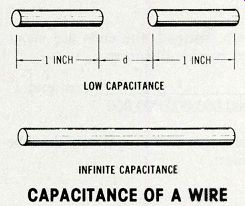
Figure
1 Two pieces of wire (A)have capacitance between them. The ultimate in minimum
distance between the plates occurs when a single piece of wire is used (B).
Therefore, the wire should have infinite capacitance, ac cording to a statement
in the February Technical Notebook. CAPACITANCE OF A WIRE
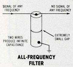
Figure 2---A capacitor of infinite capacitance should eliminate all frequencies.
ALL-FREQUENCY FILTER.
The only variable remaining is the distance (d) between the ends of the two pieces of wire. Notice, however, that the wires do not touch. Instead, the ends are separated by this distance:
1 1,000,000,000,000,000 centimeter
The capacitance equation then becomes:
1 C 1 1,000,000,000,000,000
The answer is:
C = 1,000,000,000,000,000 Farads.
That would have to be the great grandfather of all capacitors! One reader suggested that the reactance (which is 1 divided by the quantity 2 times Pi times f times c) of such a large capacitance would be zero ohms at all frequencies.
Therefore, he proposed a use for the capacitor as a filter which would remove all frequencies (see Figure 2).
Some who wrote letters about the infinite-capacitance wire thought the idea wasn't intended to be taken seriously. No comment. But, it does arouse some healthy interest in capacitance, doesn't it? Stacks of letters A mountain of mail (or at least a small mound) has accumulated, and each letter will be answered as soon as possible. Some of the interesting subjects are discussed in these articles. Send written permission if you want your name mentioned in connection with any subjects suggested in the future.
Mu metal
A reader of Woodhaven, NY asks these three questions about magnetism:
What is Mu metal, how does it work and what are some applications?
Is it possible to shield magnetic flux?
How permanent are the "permanent" magnets used in speakers and other magnetic components? The first two questions are closely related. Mu metal is a special metal which offers low opposition to magnetic flux. In other words, it has high permeability, and that makes it useful for magnetic shielding, as shown in Figure 3. However, notice that the flux lines are not eliminated, but rather are shunted around the object being shielded.
Such Mu-metal shields are used to reduce magnetic pickup of hum by microphone transformers, tape playback heads and the CRTs in scopes.

Figure 3---A Mu-metal shield forces the flux lines that normally would travel
through an object to detour around the object. Therefore, the effect is to
eliminate the flux lines that are within the shield. MAGNETIC SHIELDING.
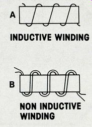
Figure 4---The secondary cable of an arc welder acted as a series inductance
that limited the welding current when it was wound in inductive fashion (A)
around the cable brackets. (B) After it was rewound in a non-inductive way,
the welder operated normally.
No figures are readily available about any weakening of permanent-magnet strength with aging. If the flux does diminish, it must be a minor amount, for it's certain the magnets outlast the cones.
Spin versus magnetism--A question about the theory of magnetism was sent in by William J. McEvoy of Oxnard, CA. He wanted to know if the lines of magnetic flux of a magnetic field are produced by alignment of the electrons spinning around the atom.
Well, it's not quite that simple. If it were, a piece of wood could be magnetized. All non-magnetic materials have spinning electrons.
If clockwise spins are called positive and counter-clockwise spins are called negative, then most materials have an equal number of positive and negative spins. There fore, no net magnetic field is associated with each atom.
Only certain materials (such as iron) have uncompensated spins. In other words, there are more spins of one direction than there are spins in the opposite direction.
Therefore, the atom has a net field in one direction. When the fields of these atoms are aligned, a magnet is produced.
Practical application of theory
Joseph Knotek of Racine, WI described an unusual problem with an arc welder. He told about an electrician who extended a welding cable to more than 200 ft. After testing the performance, he coiled the cable. A few days later, another worker reported that the welder would not work properly. Joseph reasoned correctly that the coiling of the cable had created an inductance which limited the cur rent. After the cable was rewound as shown in Figure 4, the welder worked with normal power.
At the end of the letter, he stated, "Basic theory is needed and should be used along with practical applications in troubleshooting." Recovery time A reader who lives in Oak Forest, IL asked for the derivation of diode shunt capacitance versus recovery time, as relating to a subject in the July, 1978, issue.
Company publications are valuable sources of information. The data about diode-recovery time, for example, came from a Motorola publication entitled Silicon Zener Diode and Rectifier Handbook.
A counter that skips? In a letter from Mt. Olive, NC, a reader comments that he enjoys reading Technical Notebook and mentions an error that has been corrected already. Then he asked, "How can I program a counter to skip one number while it continues to count?" It's difficult to imagine a practical use for such a counter. Anyway, the problem is presented to all readers. Design a counter that displays a count of 0, 1, 2, 3, 4, 5, 7, 8, 9 and resets back to zero after the display of 9. Notice that number 6 is omitted.
This is a contest, and the first one to send such a design will be presented with a copy of Industrial Electronics And Control, a SRA publication written by J. A. "Sam" Wilson. Another prize will be awarded to the first reader who sends a practical application for such a counter.
An ac problem A reader who lives in Flagler, CO has written, "Enjoying your Technical Notebook in Electronic Servicing, but my question deals with an item in your Howard Sams book Study Guide For Associate CET Exams. Forgive any of my mistakes, for I am a beginner in electronics." Question 12 and Figure 8-28 have been modified slightly to fit the magazine requirements. This is the way the question was stated:
In the circuit of Figure 5, both V1 and V2 measure 10 V. Therefore, the generator voltage (e) is: (a) 20 V (b) 10 V (c) 7.07 V (d) impossible to determine from the information given The book gave (d) as the correct answer.
Continuing from the letter, the reader had the impression from previous studies that 'the generator voltage could be found by use of the following formula.
EG = VER2 EL2
This is a case where some of the original material was deleted during editing, but the question was not changed. Notice that the generator voltage is labeled "E" on the drawing, but the question calls for f6e.,, One point that was supposed to be brought out by the question is that lower case letters are used for instantaneous values, and capital letters are used for RMS and average values.
The equation the reader quoted would provide the RMS value, so he was correct if he wanted the RMS voltage. However, the information is not sufficient for the instantaneous voltage to be calculated.
Although the question is not one of the better ones in the book, it becomes useless when separated from the discussion about symbolism.
Incidentally, the letters V and v are used for voltage now, and not E and e.
Ultrasonic welding
From Astoria, NY came a letter from a reader who asks for help with ultrasonic or percussion welding.
He makes synthetic emeralds in his spare time and needs the welder to fasten on the cover of a platinum cylinder that's to be used in a high-pressure high-temperature autoclave. The cover is 0.013-inch thick, and he can weld most of it with a small oxy-acetylene torch and leaving open a small portion for filling with an acid. He can't use flame on the rest because the acid fumes out.
Figure 6 is a rough drawing of the cylinder. If any reader can help, please write to Sam Wilson, in care of the magazine.
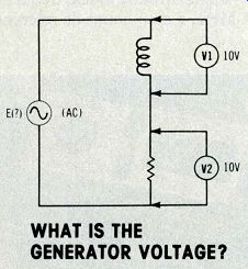
Figure 5 When part of the text was omitted from a book, the answer to the
problem (accompanying this schematic) was ambiguous.
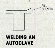
Figure 6 How can a reader weld the opening remaining at the top of this
cylinder which is to be used in an autoclave? WELDING AN AUTOCLAVE.
Also see: