By J. A. "Sam" Wilson, CET.
Your comments or questions are welcome. Please give us permission to quote from your letters. Write to Sam at:
J.A. "Sam" Wilson c/o Electronic Servicing P.O. Box 12901 Overland Park, Kansas 66212, USA.
In the December Technical Notebook, I discussed three capacitor questions that are difficult for technicians to answer. My theory is that problems arise because they are not taught how capacitors actually work. Instead, they are taught from incomplete models.
Keep in mind that this is my theory. Here, as with other controversial subjects I discuss in Technical Notebook, Electronic Servicing allows me to present my ideas. If you disagree, then your quarrel is with me, and not with the magazine.

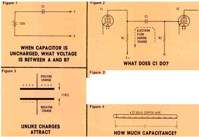
Figure 1
Figure 2 C1 is called a coupling or blocking capacitor. What does it actually do?
Figure 3 A charged capacitor has opposite charges at the plates.
These attract; therefore, work is required to move the plates apart. This work accounts for the increased voltage that occurs when the plates are separated more widely.
Figure 4

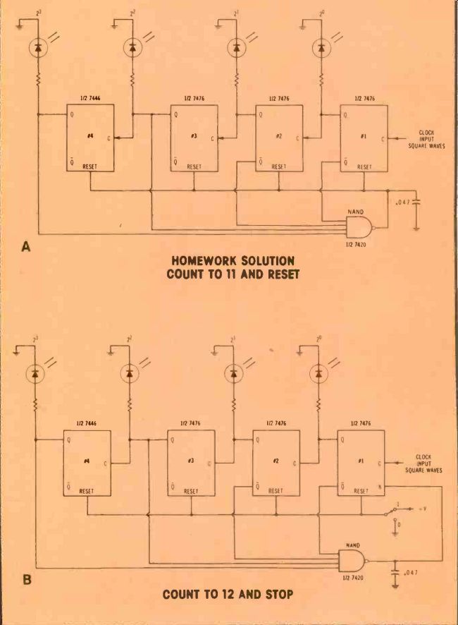
Figure 5---These are corrected schematics from the October, 1978 Industrial
Electronics article in Electronic Servicing. The A schematic was Figure 1
on page 32; B was Figure 2 on page 33; C was Figure 3 on page 36; D is the
binary counts of this Figure 5C; and E was Figure 4 on page 36.
The capacitor added to all schematics cures an unexpected glitch.
Question of the uncharged capacitor
A schematic for the last capacitor question of the series is shown in Figure 1. (I don't call it a circuit, but an arrangement, because a circuit has a complete path for current flow. A capacitor does not.) Question: What is the voltage between points A and B, if capacitor C1 is uncharged? Answer: There is 100 V between A and B.
The reasoning is quite simple. If the capacitor is uncharged, it can't have any voltage across its terminals. Therefore, the same voltage is at each of the capacitor terminals.
In other words, the voltage between A and B is identical to the battery voltage. These last two statements are true because of the zero voltage across the capacitor.
This question was used in an early version of the CET test, and it brought me more mail than any other question in any test. Why should this simple arrangement of components be so difficult to analyze? Perhaps it's because the usual capacitor model places excessive emphasis on the thought that capacitors will pass ac but not do voltages.
The circuit often used to demonstrate this idea is shown in Figure 2. Capacitor C1 sometimes is called a blocking or (more often) coupling capacitor. Its purpose often is described this way: the capacitor allows the ac signal to pass from V1 to V2, but prevents the V1 positive plate voltage from reaching the grid of V2.
The explanation is not wrong, but it omits the initial charging that occurs when the circuit first is energized. A dotted arrow shows the electron path for the charging current. After the capacitor be comes charged, the dc voltage across resistor R2 has dropped to zero volts. The do voltage across the capacitor then is equal to the B+ minus the voltage drop across R1.
Notice the similarity between the schematics of Figure 1 and Figure 2. In both cases, the capacitor is connected to a positive voltage. However, in Figure 1, the capacitor is uncharged, so the output do voltage equals the supply voltage.
In Figure 2, the capacitor is charged, and its output voltage is zero volts.
Just as soon as a conventional voltmeter (which draws current from the tested circuit) is connected between points A and B in Figure 1, the capacitor begins to charge.
Eventually, the dc output voltage will become zero volts when the capacitor reaches full charge. However, that is not a consideration in the question, because the capacitor is described as being uncharged.
In a future issue, I'll present some comments from readers about this capacitor series.
More comments about work
One reader (who didn't give permission for his name to be mentioned) asked me to give additional information about the in crease of voltage across a charged capacitor when the plates are moved apart. He asked why the voltage went up when the plates are moved farther apart but not when they are allowed to move toward each other.
The answer is found in this statement: Voltage is a unit of work. That is, work equals force multiplied by distance. When a capacitor is charged, one of the plates is positive and the other is negative (see Figure 3). Like charges repel and unlike charges attract. Therefore, the plates of a charged capacitor are attracted to each other. To move those plates apart, you must exert force through a distance.
Since the plates are attracted to each other, they will move toward each other without the need for an external force. So, it's not necessary to expend work on the system to move the plates nearer together.
When the plates are moved apart, energy is stored, and this energy is given up when the plates are returned to their original position.
Please, no phone calls 1 try to answer all letters sent by readers. Sometimes there's a long delay because I have a busy schedule. But I do answer eventually. However, I don't have a telephone. (I'm waiting to see if they catch on.) So, when people call the ISCET/NESDA office, the magazine, or my place of work, they waste their time and money. I never return phone calls because it's too much trouble to find a pay phone.
Please write to me; don't call.
A strange capacitor I just can't resist one more capacitor question. At the beginning, I must explain that I don't know of any practical application for the answer.
Question: What is the capacitance of the piece of wire in Figure 4? The answer is given at the end.
Glitch...that old demon
Many readers have written about the first four illustrations in the October, 1978 Industrial Electronics article.
Those illustrations and the accompanying text had too many errors to blame on the typesetters (our usual excuse). (Three of the schematics had NOR symbols when the gate plainly was labeled as a NAND. In Figure 3, the NAND inputs were wired incorrectly. Also, the Figure 8 caption should have referred to Figure 4, not 3.) Corrected schematics are in Figure 5.
However, even after several readers recognized the mistakes and correctly wired the counters, wrong counts were obtained.
With ripple counters, each flip flop is switched in sequence. The first switches the second, the second switches the third and so on. These counters are programmed to stop or repeat the count when all four NAND inputs receive logic 1 signals (highs). At that time, the NAND output should go low and stop the count.
Figure 6 shows the NAND input waveforms for the October Figure 1. The area of interest is the tiny slice of time between the 7 count and the 8 count. This point is marked by an arrow. Notice that signals from the first, second and fourth flip flops are changing to highs, while the signal from the third flip flop is switching to a low.
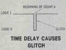
If these four waveforms switched at the same instant, there would be no problem. However, if the third flip flop signal has the slightest delay in dropping to zero, all four NAND inputs will have logic ones for a very short time before the correct states are established. This brief transient condition produces at the NAND output a glitch that's similar to the narrow negative pulse of Figure 7. Unfortunately, the glitch resets the four flip flops to zero before the counter reaches the programmed count of eleven.
A simple fix
The glitch can be eliminated by the addition of a 0.047 microfarad capacitor connected from the NAND output to ground, as shown in Figure 8 and the corrected schematics of Figure 5. The capacitor stores the narrow glitch but the value is too small to affect the correct NAND output logic states.
With the capacitor added, the counters work as intended.
Now, I don't recommend adding capacitors to solve glitch problems, unless there is no other solution.
For example, a 2-input NAND could be used to switch only two adjacent flip flops. This greatly reduces the effects of time delays.
Another design solution is to use a synchronous counter. I'll discuss that type next month.
Answer to wire capacitor
A straight piece of solid wire has an infinitely-large capacitance! Remember that moving the capacitor plates nearer together increases the capacitance. This is proved by the following equation for capacitance:
C=k NA/d
In this case, k is the dielectric constant, N is the number of paralleled plates, A is the area of each plate, and d is the distance between the plates.
Therefore, if the distance between plates is reduced to zero, the capacitance becomes infinitely large. Figure 9 shows how such a capacitor can be made from wire.
As I wrote earlier, I don't know of any practical use for this curious type of capacitor. Do you?

Figure 6--If the third flip flop signal is slow in dropping to zero at the
beginning of the eighth count, al NAND inputs will have highs for a very
brief time. However, this is long enough to produce a negative-going glitch
at the NAND output, and it stops the count prematurely.

Figure 7-- A time delay in the third flip flop can cause a glitch at the
NAND output.
The glitch resets the counters before the programmed number.

Fig. 8. A Figure 0.047 capacitor added to the NAND out put removes the glitch.

Figure 9. Sam says this lower wire has infinite capacitance.
Also see: Sam Wilson's Technical Notebook: SYNCHRONOUS COUNTERS