Diagnosing and repairing medical electronics equipment is no more difficult than servicing home-entertainment machines.
By Joseph J. Carr, CET
Electronic medical equipment is more durable and usually less complex than comparable consumer electronic merchandise. Therefore, typical repairs of medical equipment are not complicated, but more importance must be placed on competent work because of the human lives involved.
Some common and recurrent problems with medical equipment include component failures as well as defects caused by nurses and doctors.
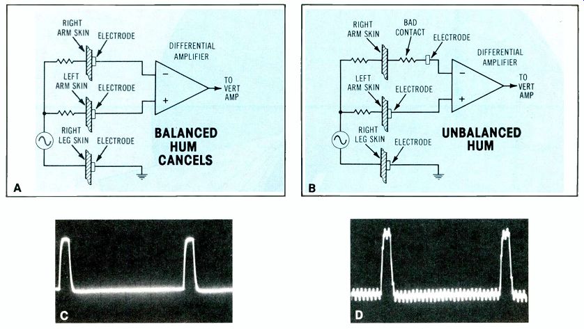
Figure 1---Differential amplifiers accept signals between the inputs
while cancelling any in-phase signals applied to both inputs. (A) Correct
connections cancel the 60Hz hum and allow the heart signals to be viewed.
(B) A bad electrode contact upsets the balance, thus reducing the cancellation
of hum and permitting hum to be mixed with the signal. (C) With an ECG
pulse simulator signal, normal balance of attached electrodes minimizes
the hum signal. (D) Hum on the pulse waveform results from bad electrode
connections.
60 Hz interference
Various muscular activities of human hearts produce corresponding electrical signals that can be monitored on the skin's surface.
These waveforms are recorded on electrocardiograms (ECGs). One possible problem is an unwanted mixture of ECG signals with 60Hz power-line waveforms.
Amplitude of the chest signals monitored by ECGs is very small, typically about 1mV, while the 60Hz signals radiated from power wiring might measure several volts.
For example, a conventional service scope will show a volt or more of distorted sine waves when the operator's finger is touched to the scope probe.
Fortunately, the 1mV heart signals can be acquired in a differential fashion, while the offending 60Hz signal is common to both ECG inputs.
Figure 1A shows the three ECG leads during normal operation. The desired signal is obtained between the right arm (RA) and left arm (LA), with the right-leg connection serving as a common ground. The IC differential amplifier accepts out-of-phase RA and LA signals from the electrodes as though they were the only inputs. The 60Hz unwanted signal is picked up in-phase by both RA and LA electrodes. This common-mode signal is cancelled inside the IC. (See Figure 1C.) A poor connection at one electrode (RA or LA) adds resistance in series with that input signal (Figure 1B). This reduces the RA/LA signal slightly, but it completely unbalances the 60Hz at those electrodes; therefore, the 60Hz interference is not cancelled (Figure 1D).
During five years of servicing medical equipment, I have seen no circuit problems that caused 60Hz interference. However, the 60Hz pattern is found almost daily in any large hospital. It invariably originates in wiring connections between the ECG and the patient.
A typical ECG patient cable is pictured in Figure 2. The instrument end of the cable has a 5-pin military-type connector, and a tip-jack terminal block is at the other end. The various electrode wires are short (16 to 24 inches) and they plug into the terminal block. Most of the breaks occur in these leader wires. They can occur at either end, but most often give trouble at the pin-tip end.
First step for troubleshooting the 60Hz problem is to short the ECG amplifier input and notice if the interference disappears. If it does, the problem is external to the ECG.
Some technicians prepare a five-pin male connector with all leads shorted together so it can serve as a "deadhead" plug. With this test connector substituted for the cable, the technician operates the lead selector on the ECG. If the base line remains stable and without any 60Hz disturbance at all positions, then the trouble is in the cable.
Next, the cable is tested by connecting it to the ECG, shorting together all leader wires, and then observing the screen while trying all positions of the lead selector. No combination of leads should show 60Hz interference.
If the 60Hz pattern persists after the ECG and its leads have been checked, there are still two possibilities: a bad connection is between an electrode and the patient's skin; or a bad power-line ground exists at the ECG machine, an electric bed, or any other instruments attached to the patient.
Adhesive on the disc electrodes tends to dry up, causing a poor connection to the skin as the electrode pulls loose. This is a simple matter to correct, but it is not the technician's duty to replace an electrode on a patient.
In fact, never touch a patient In any way, even when asked to do so by a hospital staff member. There is a principle of privacy here, and a patient might sue the hospital if a non-medical person touched him or her.
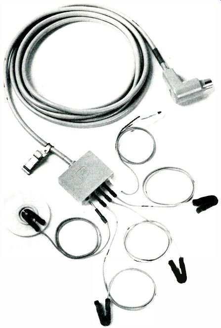
Figure 2---A typical patient ECG cable can operate with as many as five
electrode leads. Opens usually occur near the ends. (Courtesy of Electronics
For Medicine)
If the interference is gone after an electrode is changed, but reap pears about the time the technician's tools are packed, then the nurse must be informed that either a better electrode or a more-effective skin preparation is needed. Some electrodes (especially the low-cost paper disc types) don't hold properly on moist skin. The heavier type with foam-rubber backing is recommended.
The third wire of a power cable should ground the ECG instrument.
But a poor connection in the ac outlet is a common cause of 60Hz interference. Hospital-grade outlets are marked with a color dot, and are more rugged than mass-merchandised types. If a separate ground wire is connected temporarily to the ECG and it reduces the 60Hz pattern, the house electrician should be instructed to change the outlet.
Scope trace is too high In the intensive-care unit (ICU) areas of a hospital, the ECG of each patient is monitored continuously on a medical oscilloscope (a strip-chart recorder is used occasionally to provide permanent records).
When such a scope malfunctions, the complaint might be that the trace can't be moved into the upper (or lower) area of the screen, or that the upper (or lower) peaks of the waveform are clipped.
If either Q1 or Q2 of Figure 3A becomes open, then the trace can be moved only in the top or bottom of the screen, depending on which transistor is open. Both transistors are mounted on the main chassis near the filter capacitors in this Hewlett-Packard scope (Figure 3B).
Another problem involving the same vertical-output transistors is evidenced by amplitude that varies as the position control is adjusted.
In dual-trace mode, one position control often moves both traces.
The solution is to test and replace Q1 or Q2. In fact, 2N5294 transistors are not expensive, and the shotgunning replacement of both is a practical compromise.
Fuzzy ECG charts
A fuzzy or smeared tracing is the most common complaint against strip-chart recorders. Often the medical person who reports the problem will assume the trouble is a worn or "bad" stylus. Of course, this is possible, but a frequent problem is that the tracing paper has been loaded incorrectly.
Paper in an ECG machine is paraffin-treated so it turns black when heated, and the writing stylus is an electrically heated shaft (a hollow tube with a resistance heating element). The paper is pulled over a straight writing edge (Figure 4A) where the stylus contacts it.
The paper should be pulled taut at the edge, but if someone loads the paper incorrectly, the reverse tension is defeated and the trace is smeared. Incidentally, it is a simple matter to load the paper correctly, but a longer, harder job to do it incorrectly. It is advisable to be very tactful when telling a doctor or nurse that the paper was not loaded according to factory specifications.
No beam on scope
Monitor scopes are used where patients are seriously ill, and a scope that's out of order is a critical matter to the medical staff.
Without vital information from a monitor scope, they cannot anticipate a crisis or effectively respond to a crisis after it occurs. Therefore, any severe malfunction in a CCU or ICU monitor scope usually justifies an emergency service call. Few hospitals have back-up units.
Complete loss of the scope trace (assuming that strip-chart recorders in the system continue to operate) usually is caused by problems in the power supply. In fact, the power supplies of any medical equipment should be tested first with voltmeter and scope. After several breakdowns of each model, a technician begins to anticipate which supply is most likely to fail.
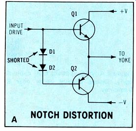
Figure
3 Vertical deflection and centering depend on push-pull transistors.
(A) The vertical-output stage resembles those of many audio amplifiers,
complete with base diodes to minimize crossover (notch) distortion. (B)
In model 7803B Hewlett-Packard ECG, the output transistors are mounted
near two filters on the main chassis.
Partial sweep
Standard sweep rate for ECG and arterial blood-pressure monitor scopes is 25mm/S, although other speeds sometimes are included. A sawtooth waveform of a 4-second repetition rate (0.25Hz) is required to sweep a standard 10cm scope screen. This deflection usually is provided by push-pull tubes or transistors.
Older tube-equipped models have sweep problems usually caused by weak or dead tubes. Some models have zener diodes that limit the maximum amplitude (Figure 5). If the zeners short, the sweep starts near the center of the screen.
Certain solid-state models using the totem-pole type of horizontal amplifier (Figure 3A) have similar symptoms when the crossover (or notch) distortion diodes are shorted.
The beam is shifted toward the middle. An examination of the sawtooth waveform by the bench scope will reveal the type of defect (Figure 6).
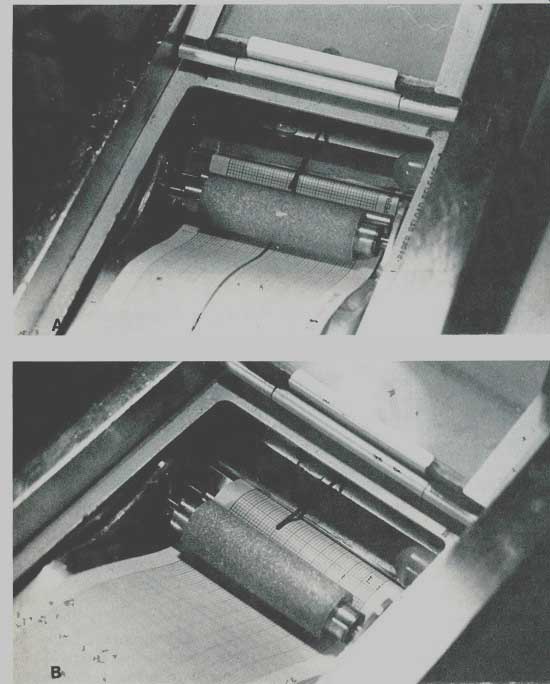
Figure 4 (A) When strip-chart ECG paper makes a sharp angle near the
heated stylus, clear traces are produced. (B) But when the paper is threaded
incorrectly (making a broad curve over the roller), all traces are blurred.
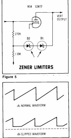
Figure 5---Driver stage of the Sanborn/ H-P model 769 has zener diodes
to limit the maximum amplitude. Shorted diodes move the trace to the
right.
Figure 6---(A) A 0.33Hz sawtooth is the correct horizontal sweep waveform in the Hewlett-Packard model 769 ECG. (B) Clipped sawteeth are produced by a defect in the horizontal sweep.
Wide trace
Model 769 multichannel scope by Sanborn (later Hewlett-Packard) has sweeps that are reversed from usual TV practice. The beam is swept horizontally by a 0.33Hz sawtooth, while the vertical height is deflected at 15.75kHz. This would produce a raster, except for blanking that eliminates the electron beam until it is needed to form one of the traces. A gating amplifier generates a pulse that un-blanks the CRT once for each channel during each vertical sweep. There fore, a dot of light appears to move from left to right across the screen for each horizontal sweep that requires 3 seconds. Actually, the dot of light is made up of many separate dots lighted in sequence.
Timing of the un-blanking pulses is determined by the input signal waveform.
A band of light across the screen instead of the expected traces can be caused by any of several defects that disrupt the beam blanking.
Loss of filtering in one of the power supplies is the usual source of these blanking problems. Look for excessive ripple and wrong dc voltages of the +6V, -6V,-200V and +250V supplies. Failure of a series-pass transistor in one of the 6V supplies can cause a band of light across the CRT screen.
Another (and more perplexing) cause of the light bands is shown in the vertical-sweep and high-voltage section (Figure 7). Notice that the circuit is similar to the horizontal sweep in monochrome TV receivers.
(In fact, if a flyback is ordered from Hewlett-Packard, the replacement will be a Triad D-604, which is familiar to many TV technicians.) C1 is the first suspect, although C3 also should be tested.
Missing section of trace
Non-fade medical scopes are special-purpose digital storage scopes. That is, they have a special semiconductor memory (that is similar to the memory in computers) rather than a storage mesh in the CRT.
As shown in Figure 8, the incoming analog waveform is digitized by an analog-to-digital (A/D) converter. Each amplitude level of the analog input waveform is converted to a binary digital number that represents the instantaneous amplitude. Typically, between 100 and 300 samples are taken every second.
The A/D converter can sample only one point at a time, so each waveform can be represented accurately by a table of binary values (which are stored in successive locations of the memory). This memory bank (a shift register circuit) is scanned as many as 100 times per second for display on the CRT screen (the CRT display is refreshed at every sweep). Then a digital-to-analog (D/A) converter changes the binary words back to the original analog levels for the scope's vertical amplifiers.
The memory is updated from the A/D once every few horizontal scans by overwriting the most recent data in place of the older data. On the CRT screen, the display gives the illusion of a real-time trace that does not fade.
Figure 8B shows one kind of symptom seen on the CRT when one of the shift registers goes bad.
The waveform has a void or gap in the part of the trace that's served by the defective shift register. Loss of data produces a black space in the trace.
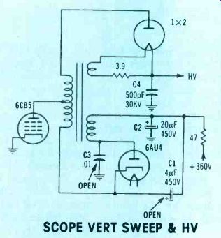
Figure 7--Circuit of the Hewlett-Packard model 769 vertical sweep is
similar to the horizontal-output stage of TVs. SCOPE VERT SWEEP & HV
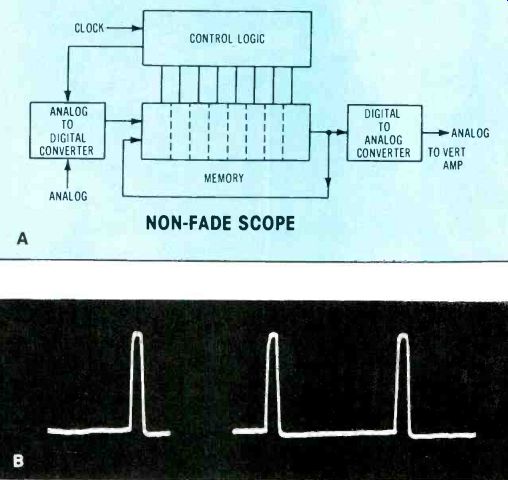
Figure 8--Medical non-fade scopes have a digital memory. A defect in
a shift register can remove part of the trace.
If one cell (that is, a single flip flop) is defective, only a single dot of trace seems to be missing.
Probably it is not worthwhile replacing an IC for such a minor symptom.
A longer gap on the CRT screen is produced when all shift register cells are either set to 00000000 or 11111111, and a wrong mark on the screen results from a few cells that are set permanently at either high or low logic states. To deter mine the type of defect, compare the incomplete waveform with the same input signal viewed on a service scope.
Comments
These descriptions of typical repairs made to medical equipment indicate that competent electronic technicians can perform equally well in this new field.
Also see: Instructing a microprocessor