By Carl Babcoke
Each report about an item of electronic test equipment is based on examination and operation of the device in the ELECTRONIC SERVICING laboratory. Personal observations about the performance, and details of new and useful features are spotlighted along with tips about using the equipment for best results.
Hickok model LX-303 digital multi-meter is pocket sized, but it has many performance and automatic features of larger instruments.
These features include a 3 1/2-digit liquid-crystal display (LCD) that is easier to read in bright lighting, automatic polarity indication, automatic zeroing, automatic overrange indication and stable, accurate readings.
DC volts
Accuracy of the five dc voltage ranges (that provide readings from 0.1mV to 1000V) is ±0.5% reading 0.5 % of full scale (FS). Input impedance is 10M-o for all ranges.
An X10 slip-over probe extends the maximum readings (and the protection) to 10kV.
AC volts
Two ac-voltage ranges (0-100v and 0-1000V) provide readings from 0.1V to 600V with ±1 % of reading ±0.5 % FS accuracy. Frequency response of the 100V range checked flat to 400Hz,-6dB at 3.5kHz, and-12dB at about 6kHz. Input impedance is rated at 4.3 M-ohm .
Resistance readings
Six ranges measure resistances between 0.10 and 19.99M0 . Ac curacy is ±0.5 % of reading .±.0.50/1) FS for all except the 20M0 range which has 1.5 % accuracy.
Voltage across the test leads at a full 1999 readout is about 300mV (0.3V). Therefore, silicon transistors and diodes do not conduct, and accurate resistance readings can be obtained in-circuit. If a diode or transistor resistance must be tested, the XIM g or X10M0 ranges should be used because of the small current.
DC current
Current between 0.01nA and 199.9mA is measured in six dc-current ranges with ±0.5 % of reading ±0.5% FS accuracy, except the 100mA range which has ±2.5 %.
Voltage drop across the meter does not exceed 200mV.
Selecting functions
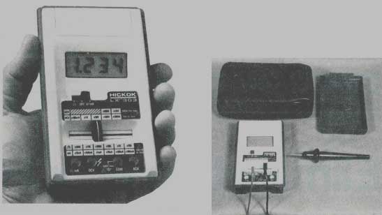
Ohms or volts/milliamperes functions are selected by the on/off switch (Figure 1). Desired ranges are obtained by sliding the range switch sideways. Multipliers for ac-voltage and dc-voltage ranges are above the range-switch knob, and those for resistance and cur rent are below. Four banana jacks (recessed to prevent electrical shocks) marked common, ohms/milliamperes, dc volts and ac volts are provided for the test leads.
Maximum count of the LCD display is 1999. For example, the 100Vdc range can show a readout up to 199.9V before overrange occurs. Overrange for any function is indicated by a steady display of the left-hand number 1 and the decimal point without other numbers (Figure 2).
Minimum life of the 9V battery is said to be 200 hours, but typically about 300 hours can be expected from an alkaline battery. A sliding door above the LCD display covers the battery.
Voltage ranges are protected to 1000Vdc or peak ac, and resistance ranges are protected to 120V.
General features
Hickok model LX-303 is small enough to fit in a hip or coat pocket.
Dimensions are 1-3/8"x3-3/8"x 5-7/8" and the weight is 12 ounces including the battery. A snap-on cover serves as storage for the two test leads and protects the meter when it is transported in tool box or tube caddy. Readings on the sharp black-on-white display are updated three times per second so tests can be finished rapidly.
Optional accessories for LX-303 include a padded carrying case, an adapter for 120Vdc operation, a 10Adc current shunt, an X10 slip over probe for dc voltage, and a 40kVdc probe for checking TV high voltages.
Comments
Comparison with several digital meters of 0.1 % ratings showed the Hickok LX-303 had good accuracy.
Also, it successfully passed the difficult test of providing accurate readings with half-wave unfiltered dc voltage. (Some digital meters give low or erratic readings during this test.) The slip-on X10 probe allowed safe readings of dc voltage at the horizontal-output tube plate and the CRT focus voltage. Also, it gave far less detuning or loading than other probes when measurements were made in IF and oscillator stages.
The sample meter performed very well on all functions, and no problems were experienced. Especially appreciated was the assurance that no meter damage will occur if the meter (with test leads and cover) is inserted into the carrying case and then tossed into a tool box.

Figure 1---Advanced features of the Hickok model LX-303 small digital
multimeter include a range-switch knob that moves sideways, and an unblinking
number 1 and decimal overrange indicator.
Figure 2---At the meter's right is the X10 dc probe, while the padded case and protective lid are above. The case is optional, but the test leads and lid are provided with the meter.
Also see: Case studies: Eliminating RF interference